EP0614059B1 - Kühler mit einem Schwingrohrkaltkopf - Google Patents
Kühler mit einem Schwingrohrkaltkopf Download PDFInfo
- Publication number
- EP0614059B1 EP0614059B1 EP19940400432 EP94400432A EP0614059B1 EP 0614059 B1 EP0614059 B1 EP 0614059B1 EP 19940400432 EP19940400432 EP 19940400432 EP 94400432 A EP94400432 A EP 94400432A EP 0614059 B1 EP0614059 B1 EP 0614059B1
- Authority
- EP
- European Patent Office
- Prior art keywords
- tube
- cold finger
- pressure
- pulsed
- oscillator
- Prior art date
- Legal status (The legal status is an assumption and is not a legal conclusion. Google has not performed a legal analysis and makes no representation as to the accuracy of the status listed.)
- Expired - Lifetime
Links
- 239000012530 fluid Substances 0.000 claims description 52
- 230000010363 phase shift Effects 0.000 claims description 8
- 230000001105 regulatory effect Effects 0.000 claims 2
- 230000006835 compression Effects 0.000 description 11
- 238000007906 compression Methods 0.000 description 11
- 238000001816 cooling Methods 0.000 description 9
- 239000000463 material Substances 0.000 description 6
- 230000000694 effects Effects 0.000 description 4
- 229940125725 tranquilizer Drugs 0.000 description 4
- 239000003204 tranquilizing agent Substances 0.000 description 4
- 230000002936 tranquilizing effect Effects 0.000 description 4
- RYGMFSIKBFXOCR-UHFFFAOYSA-N Copper Chemical compound [Cu] RYGMFSIKBFXOCR-UHFFFAOYSA-N 0.000 description 2
- 229910052802 copper Inorganic materials 0.000 description 2
- 239000010949 copper Substances 0.000 description 2
- 230000009931 harmful effect Effects 0.000 description 2
- 238000004519 manufacturing process Methods 0.000 description 2
- 230000001172 regenerating effect Effects 0.000 description 2
- 230000015556 catabolic process Effects 0.000 description 1
- 239000000470 constituent Substances 0.000 description 1
- 238000006073 displacement reaction Methods 0.000 description 1
- 239000007789 gas Substances 0.000 description 1
- 239000001307 helium Substances 0.000 description 1
- 229910052734 helium Inorganic materials 0.000 description 1
- SWQJXJOGLNCZEY-UHFFFAOYSA-N helium atom Chemical compound [He] SWQJXJOGLNCZEY-UHFFFAOYSA-N 0.000 description 1
- 238000002513 implantation Methods 0.000 description 1
- 230000010354 integration Effects 0.000 description 1
- 238000003754 machining Methods 0.000 description 1
- 238000012423 maintenance Methods 0.000 description 1
- 238000000034 method Methods 0.000 description 1
- 238000005086 pumping Methods 0.000 description 1
- 230000002441 reversible effect Effects 0.000 description 1
- 229910001220 stainless steel Inorganic materials 0.000 description 1
- 239000010935 stainless steel Substances 0.000 description 1
Images



Classifications
-
- F—MECHANICAL ENGINEERING; LIGHTING; HEATING; WEAPONS; BLASTING
- F25—REFRIGERATION OR COOLING; COMBINED HEATING AND REFRIGERATION SYSTEMS; HEAT PUMP SYSTEMS; MANUFACTURE OR STORAGE OF ICE; LIQUEFACTION SOLIDIFICATION OF GASES
- F25B—REFRIGERATION MACHINES, PLANTS OR SYSTEMS; COMBINED HEATING AND REFRIGERATION SYSTEMS; HEAT PUMP SYSTEMS
- F25B9/00—Compression machines, plants or systems, in which the refrigerant is air or other gas of low boiling point
- F25B9/14—Compression machines, plants or systems, in which the refrigerant is air or other gas of low boiling point characterised by the cycle used, e.g. Stirling cycle
- F25B9/145—Compression machines, plants or systems, in which the refrigerant is air or other gas of low boiling point characterised by the cycle used, e.g. Stirling cycle pulse-tube cycle
-
- F—MECHANICAL ENGINEERING; LIGHTING; HEATING; WEAPONS; BLASTING
- F25—REFRIGERATION OR COOLING; COMBINED HEATING AND REFRIGERATION SYSTEMS; HEAT PUMP SYSTEMS; MANUFACTURE OR STORAGE OF ICE; LIQUEFACTION SOLIDIFICATION OF GASES
- F25B—REFRIGERATION MACHINES, PLANTS OR SYSTEMS; COMBINED HEATING AND REFRIGERATION SYSTEMS; HEAT PUMP SYSTEMS
- F25B2309/00—Gas cycle refrigeration machines
- F25B2309/14—Compression machines, plants or systems characterised by the cycle used
- F25B2309/1406—Pulse-tube cycles with pulse tube in co-axial or concentric geometrical arrangements
-
- F—MECHANICAL ENGINEERING; LIGHTING; HEATING; WEAPONS; BLASTING
- F25—REFRIGERATION OR COOLING; COMBINED HEATING AND REFRIGERATION SYSTEMS; HEAT PUMP SYSTEMS; MANUFACTURE OR STORAGE OF ICE; LIQUEFACTION SOLIDIFICATION OF GASES
- F25B—REFRIGERATION MACHINES, PLANTS OR SYSTEMS; COMBINED HEATING AND REFRIGERATION SYSTEMS; HEAT PUMP SYSTEMS
- F25B2309/00—Gas cycle refrigeration machines
- F25B2309/14—Compression machines, plants or systems characterised by the cycle used
- F25B2309/1408—Pulse-tube cycles with pulse tube having U-turn or L-turn type geometrical arrangements
-
- F—MECHANICAL ENGINEERING; LIGHTING; HEATING; WEAPONS; BLASTING
- F25—REFRIGERATION OR COOLING; COMBINED HEATING AND REFRIGERATION SYSTEMS; HEAT PUMP SYSTEMS; MANUFACTURE OR STORAGE OF ICE; LIQUEFACTION SOLIDIFICATION OF GASES
- F25B—REFRIGERATION MACHINES, PLANTS OR SYSTEMS; COMBINED HEATING AND REFRIGERATION SYSTEMS; HEAT PUMP SYSTEMS
- F25B2309/00—Gas cycle refrigeration machines
- F25B2309/14—Compression machines, plants or systems characterised by the cycle used
- F25B2309/1417—Pulse-tube cycles without any valves in gas supply and return lines
-
- F—MECHANICAL ENGINEERING; LIGHTING; HEATING; WEAPONS; BLASTING
- F25—REFRIGERATION OR COOLING; COMBINED HEATING AND REFRIGERATION SYSTEMS; HEAT PUMP SYSTEMS; MANUFACTURE OR STORAGE OF ICE; LIQUEFACTION SOLIDIFICATION OF GASES
- F25B—REFRIGERATION MACHINES, PLANTS OR SYSTEMS; COMBINED HEATING AND REFRIGERATION SYSTEMS; HEAT PUMP SYSTEMS
- F25B2309/00—Gas cycle refrigeration machines
- F25B2309/14—Compression machines, plants or systems characterised by the cycle used
- F25B2309/1424—Pulse tubes with basic schematic including an orifice and a reservoir
- F25B2309/14241—Pulse tubes with basic schematic including an orifice reservoir multiple inlet pulse tube
Definitions
- the present invention relates to coolers based on the Stirling cycle. These coolers allow to reach cryogenic temperatures.
- coolers include an oscillator electromechanical which generates, in an active enclosure containing a fluid, a pressure wave.
- the enclosure has a part equipped with a mobile regenerator or displacer which uses the expansion and compression cycles of the fluid to achieve Stirling cycle.
- the fluid used is generally helium, under an average pressure of several hundred kilopascals.
- the oscillator can be rotary or linear.
- the cold part generally has, to limit the heat losses by conduction and facilitate its manufacture, shape of a very elongated cylinder which earned him the name of "cold finger".
- the free end of the cold finger provides cooling capacity created by the expansion of the fluid.
- the base cold finger connected to the oscillator dissipates heat created by compression of the fluid.
- the cold finger is usually immersed in a cryostat, such as a vase of Dewar for example, which contains the device to be cooled.
- the interior of the cryostat is generally subjected to vacuum to limit heat input.
- the oscillator and the cold finger constitute one piece.
- the movement of regenerative is generally ensured, in the case of a rotary oscillator, by the oscillator piston.
- This configuration is very compact, it limits losses of charge between the oscillator and the cold finger. But the vibrations induced by the oscillator are transmitted to the device to be cooled.
- the oscillator and cold finger are distant but connected by a pneumatic conduit which ensures the transfer of the pressure wave between the oscillator and the cold finger.
- the movement of the regenerator can be provided by a specific motor or by the effects tires generated by the pressure wave.
- the first one configuration is typically used in applications spatial. These two configurations make it possible to separate the oscillator and the equipment to be cooled which facilitates integration of the chiller into the environment of the device to be cooled. In addition, these two configurations significantly reduce vibrations at the level of the device to be cooled.
- Mobile regenerative coolers come at a cost relatively high due to the required machining tolerances to realize the regenerator and the cold finger which are in movement relative to each other.
- Pulsed tube type cold finger coolers are also known.
- the cold finger instead of containing a mobile regenerator contains a fixed regenerator and a tube pulsed.
- coolers in the as they use a double orifice pulsed tube, have a yield substantially equivalent to that of a cold finger cooler fitted with a mobile regenerator. A double orifice pulsed tube cooler is described later in Figure 1.
- the major drawback of this type of cooler is related to the U shape of the cold finger.
- One of the branches of the U is made by the regenerator and the other by the pulsed tube.
- the base of the U which is also the free end of the cold finger is formed of an integral end piece on one side of the regenerator and on the other of the pulsed tube.
- This cold finger imposes a specific cryostat and therefore prevents its implantation in a cryostat intended for a cold finger with regenerator mobile or Joule-Thomson type.
- On-site maintenance of the cold finger with pulsed tube is not possible while intervention on a cold finger with mobile regenerator is easy. Indeed, it would be necessary to break the vacuum cryostat to disassemble the pulsed tube or the regenerator.
- the present invention aims to remedy these drawbacks.
- She offers a cooler based on the Stirling cycle, fitted with a cold finger pulsed tube type.
- This cooler can be installed in a cryostat classic and it has good thermodynamic performance.
- the cooler according to the invention comprises means for generating and transmitting a pressure wave in a fluid to a cold finger of the pulsed tube type.
- the cold finger has a regenerator pneumatically connected to the pulsed tube, this regenerator is tubular and is mounted coaxially around the pulsed tube.
- the regenerator is contained in an outer tube, the inner surface of the regenerator serving as a pulsed tube.
- the outer tube serves as the inner wall of the cryostat. This configuration that removes the inner wall of the cryostat improves cooling performance by reducing conduction losses.
- FIG. 1 represents a cooler based on the cycle of Stirling provided with a cold finger 1 of the pulsed tube type 5, according to known art.
- the cold finger 1 is connected to a pressure oscillator 2 through a base 3.
- the base 3 provides the mechanical interface and the seal between the cold finger 1 and the cryostat in which we usually plunge the cold finger 1.
- the base 3 forms the base of the cold finger 1.
- the cryostat is not shown for reasons of clarity.
- the pressure oscillator 2 generates a pressure wave in a fluid and the fluid is successively compressed and expanded.
- the cold finger 1 comprises a fixed regenerator 4 contained in a tube 7 and a pulsed tube 5 which form the two branches of a U.
- Regenerator 4 has the shape of a cylinder full.
- the base of the U is made by an end piece 6 cold which pneumatically connects regenerator 4 and the tube pulsed 5.
- the tube 7 containing the regenerator has one end hot end fixed to the base 3 and a cold end fixed to the end piece 6.
- the end piece 6 constitutes the free end of the cold finger 1. This is the coldest point from the cooler. It is also used to transmit the device to cool, placed nearby, the frigories returned available through the expansion of the fluid.
- the fixed regenerator 4 works in the same way than a mobile regenerator. It is made of a material porous fluid permeable. Regenerator 4 is connected pneumatically with oscillator 2.
- the regenerator's function is to capture cold at fluid when the latter is sucked in by oscillator 2 during the relaxation phase and to dissipate heat towards this fluid when it is driven back during the compression phase.
- the pulsed tube 5 simply consists of a tube substantially parallel to the tube 7 containing the regenerator 4. It is attached to a cold end of the end piece 6 and at the other hot end of the base 3.
- a pneumatic circuit 8 is used to connect the oscillator 2 pressure to the regenerator 4 and to the pulsed tube 5.
- a tank buffer 9 is also provided and connected to the pneumatic circuit 8. It has sufficient volume for the fluid it contains to remain at a substantially constant pressure whatever the phase of the pressure oscillator 2. When the oscillator sucks the fluid, the fluid in the buffer tank 9 feeds the pulsed tube 5 and when oscillator 2 discharges, the discharged fluid fills the buffer tank 9.
- the pneumatic circuit includes a first conduit 81 connecting the regenerator 4 to the oscillator 2, a second conduit 82 connecting the hot end of the pulsed tube 5 to the buffer tank 9 and a third conduit 83 connecting the hot end of the pulsed tube to the pressure oscillator 2.
- the pulsed tube is connected to both the oscillator and the buffer tank.
- the fluid passes through a hot heat exchanger 10 between the hot end of the pulsed tube 5 and the oscillator 2 and / or the buffer tank 9.
- This hot exchanger 10 can be housed in the base 3.
- the third conduit 83 is arranged between the first conduit 81 and the second conduit 82 and there reaches the second conduit 82 between the buffer tank 9 and the hot heat exchanger 10.
- the hot heat exchanger 10 ensures the capture of the heat of compression of the fluid leaving the pulsed tube and its discharge, via base 3, to the outside of the cooler.
- the movement of the fluid in the cold finger is out of phase with the pressure wave generated by the oscillator 2.
- the phase shift and the flow rates at the ends hot from pulsed tube 5 and tube 7 containing the regenerator 4 are a function of the pneumatic impedance of the conduits 81, 82 and 83 and the volume of the buffer tank 9.
- the setting of the pneumatic impedance of the conduits can be done by a choice adequate their section, their length. Ducts can also have simple pinches or holes 11 calibrated as in Figure 1 or even valves.
- the behavior of the fluid in the pulsed tube is the next: consider a volume A of fluid which transits between the cold end of the pulsed tube 5 and the end piece 6. From phase shift of fluid movement in the cold finger with the expansion and compression phases of oscillator 2, this fluid when it relaxes passes to the end piece 6 while cooling and when it compresses, enters the pulsed tube 5 where it heats up almost adiabatically.
- the cooler in Figure 2 is comparable to that of figure 1.
- the main difference is at cold finger level 21 which instead of having a regenerator and a pulsed tube configured in U has a tubular regenerator 24 mounted coaxially around the tube pulsed 25.
- the cold finger 21 is always connected to an oscillator 2 through a base 3.
- Base 3 plays the same role as on Figure 1.
- the free end of the cold finger always ends by an end piece 26. It is always the most cooler.
- Regenerator 24 plays the same role as in art known. Instead of having the shape of a full cylinder it has now the shape of a tube. Regenerator 24 is contained between an outer tube 27 and an inner tube 28.
- the outer tube 27 cylindrical has a hot end fixed tightly to the base 3 and a cold end fixed in a sealed manner to the end piece 26. It forms the outer surface of the finger cold 21.
- This outer tube 27 preferably has a thickness as fine as possible to limit thermal input on along the cold finger. It is preferably carried out in a material with a thermal conductivity as low as possible, for example stainless steel.
- This outer tube 27 as well as its attachments to the base 3 and to the end piece 26 must seal the inside of the cold finger vis-à-vis the external environment.
- the cold finger is usually immersed in a cryostat subjected to vacuum. This cryostat is represented with the reference 30 in FIG. 4 in the form of a Dewar vase.
- the inner tube 28 serves both as a pulsed tube and inner wall of tubular regenerator 24. He is willing coaxially in the outer tube 27 and has a hot end fixed to the base 3. Its other end which is cold opens out in the end piece 26.
- This internal tube 28 is not like the outer tube 27 subjected to pressure differences important. It doesn't have to be strictly waterproof like the outer tube. It avoids a direct passage of the fluid from regenerator 24 to pulsed tube 25 without passing through the end piece 26.
- the design of this internal tube 28 with regard to the choice of the constituent material, its mode of fixing, and its thickness can be more easily optimized. According to the invention we physically remove the inner tube 28, the inner surface of the regenerator 24 being waterproof. In this case, it is the inner surface of the regenerator which serves as a pulsed tube.
- End piece 26 looks like parts end of cold fingers with mobile regenerator.
- the regenerator and the pulsed tube communicate pneumatically thanks to her.
- the thickness of the end piece 26 will be as low as possible. It will be carried out in a material with a thermal conductivity as high as possible: copper for example.
- the end piece contains a cold exchanger 29 formed by example of copper grates brazed at their periphery. This cold exchanger 29 improves the heat exchange between the fluid and the end piece 26.
- the material of the end piece 26 will have, from preferably a coefficient of expansion as low as possible when cold finger 21 is used to cool a device placed directly on the end piece 26 (technique known by the Anglo-Saxon name of Integrated Dewar Cooler Assembly).
- the end piece 26 could, for example, be provided with a tranquilizer to ensure a level the lowest possible turbulence in the pulsed tube 25. It it is indeed desirable to maintain a thermal gradient important between the two hot and cold ends of the tube pulsed.
- This transquillizing device can be produced by a honeycomb or cold exchanger part 29.
- the others elements of the cooler, namely oscillator 2, the circuit pneumatic 8, the buffer tank 9 and the hot exchanger 10 are comparable to those in Figure 1.
- the hot exchanger 10 if it is configured with grids or a honeycomb material also has a role in tranquilizer.
- Optimal adjustment of phase shift and amplitude of fluid flows in the regenerator 24 and the pulsed tube 25 will depend on the volume of the buffer tank 9 and the characteristics of the conduits 81, 82, 83 as before.
- the pulsed tube has a length of 70 mm and that in operation its extreme temperatures are 80 ° K at the cold end and 300 ° K at the hot end. It is assumed that the thermal gradient is linear in the wall of the pulsed tube, that the average pressure in the pulsed tube is 35.10 5 Pa and that it varies more or less 10 6 Pa, because of the pressure wave.
- the fluid slice will have an average temperature of 190 ° K but during the expansion and compression cycles, it will see its temperature oscillate between 166 ° K and 210 ° K (curve C1). This slice of fluid will be opposite with a section of pulsed tube whose temperatures will be between 158 ° K and 221 ° K (curve C2) because of the thermal gradient linear.
- the fluid In the expansion phase, the fluid will be in contact with a portion of pulsed tube cooler than him and will tend to give it heat. Symmetrically, in the phase of compression, the fluid will be in contact with a portion of tube pulsed hotter than him and will tend to extract from it heat. This heat pumping effect from the hot end of the tube pulsed towards the cold end is harmful for the cooler efficiency.
- These heat exchanges with walls only concern part of the fluid: the boundary layer thermal which is close enough to the wall to have the time to exchange, mainly by gas conduction, the heat during a compression-expansion cycle.
- Such cooler reduces trade between the fluid and the wall of the pulsed tube by placing the tube pulsed inside the regenerator and not around.
- the cold finger is formed of two tubes (thick null to simplify) coaxial diameters 5mm and 3.5mm, in the case of a thermal boundary layer thickness of 0.2 mm, we can estimate that only 20% of fluid participates in heat exchange with the wall of the pulsed tube, if the tube pulse is placed inside the regenerator, while more than 50 of fluid participates in the heat exchange with the walls external and internal of the pulsed tube, if the regenerator is placed inside the pulsed tube.
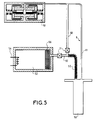
- Figures 4 and 5 show variants of a cooler with tubular regenerator mounted coaxially around the pulsed tube. We refer to figure 4.
- the cold finger is immersed in a cryostat such as a Dewar 30 vase with two speakers 31, 32 inserted one inside the other and separated by a vacuum.
- the internal enclosure 32 has the shape of a well.
- the device to be cooled referenced 33 is disposed between the external enclosure 31 and the internal enclosure 32. It is fixed to the bottom of the well.
- a thermal coupler 34 is inserted between the free end of the cold finger 21 and the bottom of the well to optimize the cooling of the device to cool 33.
- the pressure oscillator 2 is rotary.
- the reservoir buffer consists of the housing 35 of the oscillator which saves space.
- the second conduit 82 and the third conduit 83 each have a valve 36 instead of a calibrated orifice, and in addition, the second conduit 82 is provided with a pinch 37 between the valve and the hot exchanger 10.
- the pressure oscillator 51 is a resonant linear oscillator.
- the buffer tank 52 is provided with a heater 54.
- the temperature of the fluid in the buffer tank 52 is adjustable so that it can adjust the average pressure in the cooler and to be able adjust the resonant frequency of the cooler. this is particularly interesting in the case where the cooler is used in a satellite where we are looking for a frequency adjustable to avoid exciting the platform or instruments near the cooler.
- the hot heat exchanger consists of a device with fins 55 or equivalent. This device 55 is arranged on the second conduit 82 connecting the pulsed tube to the buffer tank 52.
- the other conduits 81, 83 and the tank 52 could also participate in the evacuation of the heat of compression of the fluid. To this end, they would be fitted with devices, fins for example, improving the dissipation of this heat outwards.
- the buffer tank 52 is provided with a device tranquilizer 56 to ensure a level of turbulence too as low as possible in the pulsed tube.
- tranquilizer 56 may be of the same nature as that described in the end piece 26 of FIG. 2.
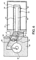
- FIG. 6 shows a cooler according to the invention.
- Cold finger 60 immersed in a cryostat 61, and the rotary pressure oscillator 68 form a monobloc cooler.
- Compressor housing 69 constitutes the buffer tank.
- the cold finger 60 has a external tube 62, a tubular regenerator 63 and a pulsed tube 66.
- the outer tube 62 serves as a wall inside the cryostat.
- the inner surface of the regenerator tubular serves as a pulsed tube 66.
- the removal of the wall inside the cryostat can of course be used in other configurations.
- the cooling device 65 is directly attached to the end piece 64 which connects the pulsed tube and the regenerator.
- the cooling is improved compared to the configuration where the outer tube and the inner wall of the cryostat are separate.
- a cooler 67 with circulating fluid around of the hot exchanger 10.
- This cooling device is preferably used when the pulsed tube is subjected to significant powers, for example greater than a few watts.
- a circulation of fluid one could have used a device of natural or forced convection cooling with air for example.
- the configuration shown is particularly compact, it minimizes the losses of load between oscillator 68 and cold finger 60.
- the cooler has now several pressure oscillators 70, 71, 72 mounted in parallel.
- a switch 73 having several input channels and an exit route allows the cold finger to be connected to one of the pressure oscillators 71.
- the pressure oscillator With a cold finger without a coin mobile, the only element presenting a risk of breakdown relatively high is the pressure oscillator which has moving parts. Switching from a pressure oscillator to a other can be controlled by the user or automatically when the operation of the oscillator in service is no longer normal. This switching requires neither intervention nor disassembly on the cold finger and the cryostat, it can be perform instantly and remotely.
- the cooler according to the invention can cool any device including sensors or detectors, components electronics, samples, etc ...
Landscapes
- Engineering & Computer Science (AREA)
- Physics & Mathematics (AREA)
- Mechanical Engineering (AREA)
- Thermal Sciences (AREA)
- General Engineering & Computer Science (AREA)
Claims (12)
- Kühler auf der Basis des Stirlingzyklus mit Mitteln zur Erzeugung einer Druckwelle in ein Fluid und zur Übertragung dieser Druckwelle auf einen kalten Finger (60) vom Typ eines gepulsten Rohrs (66) mit einem rohrförmigen Regenerator (63), der pneumatisch an das gepulste Rohr (66) gekoppelt, koaxial um das gepulste Rohr herum angeordnet ist und in einem äußeren Rohr (62) sitzt, dadurch gekennzeichnet, daß die innere Oberfläche des Regenerators (63) als gepulstes Rohr dient.
- Kühler nach Anspruch 1, dadurch gekennzeichnet. daß der kalte Finger in einen Kryostat eingetaucht ist, wobei das äußere Rohr (62) die Innenwand des Kryostat bildet.
- Kühler nach einem der Ansprüche 1 oder 2, dadurch gekennzeichnet, daß die Mittel zur Erzeugung der Druckwelle und zu Übertragung dieser Welle auf den kalten Finger einen Druckoszillator (68), einen Puffertank (69) und eine Pneumatikleitung (8) enthalten, die den Druckoszillator (68) und den Puffertank (69) mit der Basis des kalten Fingers (60) verbindet.
- Kühler nach Anspruch 3, dadurch gekennzeichnet, daß die Pneumatikleitung (8) einen ersten Leitungsbereich (81) zwischen dem Druckoszillator (68) und dem Regenerator (63), einen zweiten Leitungsbereich (82) zwischen dem Puffertank (69) und dem gepulsten Rohr (66) und einen dritten Leitungsbereich zwischen dem Druckoszillator (68) und dem gepulsten Rohr (66) aufweist.
- Kühler nach einem der Ansprüche 3 oder 4, dadurch gekennzeichnet, daß der Druckoszillator (68) ein als Puffertank wirkendes Gehäuse besitzt.
- Kühler nach einem der Ansprüche 3 bis 5, dadurch gekennzeichnet, daß das Fluid einen warmen Wärmetauscher (10) zwischen dem Druckoszillator (68) und/oder dem Puffertank (69) und dem gepulsten Rohr (66) durchströmt.
- Kühler nach einem der Ansprüche 1 bis 6, dadurch gekennzeichnet, daß das Fluid einen kalten Wärmetauscher zwischen dem Regenerator (63) und dem gepulsten Rohr (66) in Höhe des freien Endes des kalten Fingers (60) durchströmt.
- Kühler nach einem der Ansprüche 3 bis 7, in dem der Druckoszillator (51) ein linear schwingender Oszillator ist, dadurch gekennzeichnet, daß eine Vorrichtung (54) die Temperatur des Fluids in dem Puffertank (52) und damit dessen Druck zu verändern vermag, sodaß die Resonanzfrequenz des Kühlers einstellbar ist.
- Kühler nach einem der Ansprüche 1 bis 8, in der eine Phasenverschiebung der Druckwelle zwischen dem Drukkoszillator (68) und dem kalten Finger (60) existiert, dadurch gekennzeichnet, daß die Pneumatikleitung Mittel zur Einstellung dieser Phasenverschiebung enthält.
- Kühler nach Anspruch 9, dadurch gekennzeichnet, daß die Mittel zur Einstellung der Phasenverschiebung darin bestehen, die Länge und/oder den Querschnitt der Leitungsbereiche (81, 82, 83) zu justieren.
- Kühler nach einem der Ansprüche 9 oder 10, dadurch gekennzeichnet, daß mindestens einer der Leitungsbereiche (81, 82, 83) mindestens ein Element wie eine Engstelle in seiner Wand, einen geeichten Durchlaß oder ein Ventil besitzt, sodaß die Phasenverschiebung der Druckwelle eingestellt werden kann.
- Kühler nach einem der Ansprüche 3 bis 11, dadurch gekennzeichnet, daß er mehrere parallel geschaltete Oszillatoren (70, 71, 72) enthält und daß ein Umschalter (73) den kalten Finger mit einem der Druckoszillatoren (71) zu verbinden vermag.
Applications Claiming Priority (2)
| Application Number | Priority Date | Filing Date | Title |
|---|---|---|---|
| FR9302376 | 1993-03-02 | ||
| FR9302376A FR2702269B1 (fr) | 1993-03-02 | 1993-03-02 | Refroidisseur muni d'un doigt froid du type tube pulsé. |
Publications (2)
| Publication Number | Publication Date |
|---|---|
| EP0614059A1 EP0614059A1 (de) | 1994-09-07 |
| EP0614059B1 true EP0614059B1 (de) | 1998-12-16 |
Family
ID=9444568
Family Applications (1)
| Application Number | Title | Priority Date | Filing Date |
|---|---|---|---|
| EP19940400432 Expired - Lifetime EP0614059B1 (de) | 1993-03-02 | 1994-03-01 | Kühler mit einem Schwingrohrkaltkopf |
Country Status (3)
| Country | Link |
|---|---|
| EP (1) | EP0614059B1 (de) |
| DE (1) | DE69415187T2 (de) |
| FR (1) | FR2702269B1 (de) |
Cited By (1)
| Publication number | Priority date | Publication date | Assignee | Title |
|---|---|---|---|---|
| CN106556210A (zh) * | 2016-11-16 | 2017-04-05 | 浙江大学 | 压缩机与制冷机冷头耦合用l型声学匹配组件及制冷机 |
Families Citing this family (21)
| Publication number | Priority date | Publication date | Assignee | Title |
|---|---|---|---|---|
| US5613365A (en) * | 1994-12-12 | 1997-03-25 | Hughes Electronics | Concentric pulse tube expander |
| FR2736710B1 (fr) * | 1995-07-12 | 1997-08-08 | Commissariat Energie Atomique | Refrigerateur ou pompe a chaleur a tube de pulsation alimente par un generateur de pression |
| US5680768A (en) * | 1996-01-24 | 1997-10-28 | Hughes Electronics | Concentric pulse tube expander with vacuum insulator |
| FR2747767B1 (fr) * | 1996-04-23 | 1998-08-28 | Cryotechnologies | Cryostat pour refroidisseur cryogenique et refroidisseurs comportant un tel cryostat |
| FR2748469B1 (fr) * | 1996-05-07 | 1998-07-31 | Thomson Csf | Utilisation d'une barriere en nitrure pour eviter la diffusion d'argent dans du verre |
| FR2760076B1 (fr) * | 1997-02-21 | 1999-05-07 | Cryotechnologies | Dispositif de refroidissement cryogenique a oscillateur de pression a double effet |
| NL1007316C1 (nl) * | 1997-10-20 | 1999-04-21 | Aster Thermo Akoestische Syste | Thermo-akoestisch systeem. |
| US6330800B1 (en) * | 1999-04-16 | 2001-12-18 | Raytheon Company | Apparatus and method for achieving temperature stability in a two-stage cryocooler |
| US6378312B1 (en) * | 2000-05-25 | 2002-04-30 | Cryomech Inc. | Pulse-tube cryorefrigeration apparatus using an integrated buffer volume |
| KR100393792B1 (ko) * | 2001-02-17 | 2003-08-02 | 엘지전자 주식회사 | 맥동관 냉동기 |
| RU2206027C2 (ru) * | 2001-04-09 | 2003-06-10 | Формозов Борис Николаевич | Криостатированная фотоприемная система для внеатмосферной астрономии, космических исследований и дистанционного зондирования земли |
| US6755027B2 (en) | 2002-04-10 | 2004-06-29 | The Penn State Research Foundation | Cylindrical spring with integral dynamic gas seal |
| US6725670B2 (en) | 2002-04-10 | 2004-04-27 | The Penn State Research Foundation | Thermoacoustic device |
| US6792764B2 (en) | 2002-04-10 | 2004-09-21 | The Penn State Research Foundation | Compliant enclosure for thermoacoustic device |
| US7296418B2 (en) * | 2005-01-19 | 2007-11-20 | Raytheon Company | Multi-stage cryocooler with concentric second stage |
| US7628022B2 (en) * | 2005-10-31 | 2009-12-08 | Clever Fellows Innovation Consortium, Inc. | Acoustic cooling device with coldhead and resonant driver separated |
| CN100424443C (zh) * | 2007-06-04 | 2008-10-08 | 中国科学院上海技术物理研究所 | 一种用于同轴型脉管制冷机的整体式冷头 |
| US8079224B2 (en) * | 2007-12-12 | 2011-12-20 | Carleton Life Support Systems, Inc. | Field integrated pulse tube cryocooler with SADA II compatibility |
| CN101298947B (zh) * | 2008-06-26 | 2010-06-09 | 上海交通大学 | 螺纹焊接整体狭缝式同轴脉管制冷机 |
| CN103884126B (zh) * | 2012-12-19 | 2016-02-10 | 中国科学院理化技术研究所 | 同轴型脉冲管制冷机 |
| RU170671U1 (ru) * | 2016-12-02 | 2017-05-03 | Акционерное общество "Конструкторское бюро точного машиностроения имени А.Э. Нудельмана" | Комбинированная система глубокого охлаждения фотоприемных устройств |
Family Cites Families (9)
| Publication number | Priority date | Publication date | Assignee | Title |
|---|---|---|---|---|
| NL89608C (de) * | 1954-02-18 | |||
| US3188818A (en) * | 1963-11-12 | 1965-06-15 | Little Inc A | Refrigeration method and apparatus embodying fluid expansion |
| GB1202203A (en) * | 1966-08-02 | 1970-08-12 | Hymatic Eng Co Ltd | Improvements relating to refrigerating apparatus |
| US3877239A (en) * | 1974-03-18 | 1975-04-15 | Hughes Aircraft Co | Free piston cryogenic refrigerator with phase angle control |
| US3906739A (en) * | 1974-08-26 | 1975-09-23 | Us Army | Variable pneumatic volume for cryogenic coolers |
| US4412423A (en) * | 1982-06-16 | 1983-11-01 | The United States Of America As Represented By The Secretary Of The Army | Split-cycle cooler with improved pneumatically-driven cooling head |
| US4713939A (en) * | 1986-05-23 | 1987-12-22 | Texas Instruments Incorporated | Linear drive motor with symmetric magnetic fields for a cooling system |
| EP0500992B1 (de) * | 1991-02-28 | 1993-06-09 | Mitsubishi Denki Kabushiki Kaisha | Kryogene Kältemaschine |
| DE4234678C2 (de) * | 1991-10-15 | 2003-04-24 | Aisin Seiki | Reversible Schwingrohr-Wärmekraftmaschine |
-
1993
- 1993-03-02 FR FR9302376A patent/FR2702269B1/fr not_active Expired - Fee Related
-
1994
- 1994-03-01 DE DE1994615187 patent/DE69415187T2/de not_active Expired - Lifetime
- 1994-03-01 EP EP19940400432 patent/EP0614059B1/de not_active Expired - Lifetime
Cited By (2)
| Publication number | Priority date | Publication date | Assignee | Title |
|---|---|---|---|---|
| CN106556210A (zh) * | 2016-11-16 | 2017-04-05 | 浙江大学 | 压缩机与制冷机冷头耦合用l型声学匹配组件及制冷机 |
| CN106556210B (zh) * | 2016-11-16 | 2019-01-29 | 浙江大学 | 压缩机与制冷机冷头耦合用l型声学匹配组件及制冷机 |
Also Published As
| Publication number | Publication date |
|---|---|
| DE69415187D1 (de) | 1999-01-28 |
| FR2702269B1 (fr) | 1995-04-07 |
| EP0614059A1 (de) | 1994-09-07 |
| FR2702269A1 (fr) | 1994-09-09 |
| DE69415187T2 (de) | 1999-05-20 |
Similar Documents
| Publication | Publication Date | Title |
|---|---|---|
| EP0614059B1 (de) | Kühler mit einem Schwingrohrkaltkopf | |
| EP1969294A2 (de) | Vorrichtung zur kälte- und wärmeerzeugung durch einen magnetokalorischen effekt | |
| WO2004059221A1 (fr) | Procede et dispositif pour generer en continu du froid et de la chaleur par effet magneto-calorique | |
| EP3011249B1 (de) | Kühlung von elektronischen und/oder elektrischen komponenten durch gepulste wärmerohre und wärmeleitungselemente | |
| WO2004059222A1 (de) | Procede et dispositif de generation de froid et de chaleur par effet magneto-calorique | |
| EP0947787B1 (de) | Vorrichtung für eine thermische Verbindung in einer kryogenen Maschine | |
| FR2914050A1 (fr) | Refrigerateur a basse ou tres basse temperature et procede de refrigeration | |
| FR2717563A1 (fr) | Refroidisseur à gaz pulsé. | |
| EP2677230B1 (de) | Anordnung für elektronisches Bauteil zum Abkühlen, diese Anordnung umfassende Zelle, Vakuumkühlsystem, das eine solche Zelle umfasst, und Einsatzverfahren dieses Vakuumkühlsystem | |
| CN111403504A (zh) | 一种大靶面探测器阵列式多级半导体制冷方法 | |
| FR2671230A1 (fr) | Doigt de refroidissement d'un circuit semi-conducteur et dispositif cryogenique pourvu d'un tel doigt. | |
| EP4025845B1 (de) | Regenerative kryogene maschine | |
| FR2523699A1 (fr) | Appareil miniature de refroidissement cryogenique, notamment pour capteurs infrarouges | |
| EP0860667B1 (de) | Konditionierungsanordnung von bei Tiefsttemperatur arbeitenden Bauteilen | |
| EP0803687A1 (de) | Kryostat für Tiefsttemperatur-Kälteanlage und Kälteanlagen mit einem solchen Kryostat | |
| FR2734942A1 (fr) | Disposition de capteur munie d'un capteur refroidi par un refroidisseur joule-thomson et munie de composants electroniques | |
| FR2750481A1 (fr) | Refroidisseur a gaz pulse | |
| FR2834127A1 (fr) | Photodetecteur refroidi | |
| EP2318785B1 (de) | Magnetokalorischer wärmegenerator | |
| FR3072450B1 (fr) | Bouteille pour condenseur de vehicule automobile | |
| EP0494001A1 (de) | Kühlfinger für Halbleiterschaltung und kryogenische Anordnung mit solchem Finger | |
| WO1997003327A1 (fr) | Refrigerateur ou pompe a chaleur a tube de pulsation alimente par un generateur de pression | |
| JP2792004B2 (ja) | 冷凍機 | |
| FR2747766A1 (fr) | Dispositif de refrigeration thermo-acoustique | |
| FR2773392A1 (fr) | Procede et dispositif de climatisation par tubes a gaz pulse |
Legal Events
| Date | Code | Title | Description |
|---|---|---|---|
| PUAI | Public reference made under article 153(3) epc to a published international application that has entered the european phase |
Free format text: ORIGINAL CODE: 0009012 |
|
| AK | Designated contracting states |
Kind code of ref document: A1 Designated state(s): DE FR GB |
|
| 17P | Request for examination filed |
Effective date: 19950228 |
|
| 17Q | First examination report despatched |
Effective date: 19960906 |
|
| GRAG | Despatch of communication of intention to grant |
Free format text: ORIGINAL CODE: EPIDOS AGRA |
|
| GRAG | Despatch of communication of intention to grant |
Free format text: ORIGINAL CODE: EPIDOS AGRA |
|
| GRAG | Despatch of communication of intention to grant |
Free format text: ORIGINAL CODE: EPIDOS AGRA |
|
| GRAH | Despatch of communication of intention to grant a patent |
Free format text: ORIGINAL CODE: EPIDOS IGRA |
|
| GRAH | Despatch of communication of intention to grant a patent |
Free format text: ORIGINAL CODE: EPIDOS IGRA |
|
| GRAA | (expected) grant |
Free format text: ORIGINAL CODE: 0009210 |
|
| AK | Designated contracting states |
Kind code of ref document: B1 Designated state(s): DE FR GB |
|
| REF | Corresponds to: |
Ref document number: 69415187 Country of ref document: DE Date of ref document: 19990128 |
|
| GBT | Gb: translation of ep patent filed (gb section 77(6)(a)/1977) |
Effective date: 19990122 |
|
| PLBE | No opposition filed within time limit |
Free format text: ORIGINAL CODE: 0009261 |
|
| STAA | Information on the status of an ep patent application or granted ep patent |
Free format text: STATUS: NO OPPOSITION FILED WITHIN TIME LIMIT |
|
| 26N | No opposition filed | ||
| REG | Reference to a national code |
Ref country code: GB Ref legal event code: IF02 |
|
| PGFP | Annual fee paid to national office [announced via postgrant information from national office to epo] |
Ref country code: FR Payment date: 20130325 Year of fee payment: 20 Ref country code: DE Payment date: 20130227 Year of fee payment: 20 Ref country code: GB Payment date: 20130228 Year of fee payment: 20 |
|
| REG | Reference to a national code |
Ref country code: DE Ref legal event code: R071 Ref document number: 69415187 Country of ref document: DE |
|
| REG | Reference to a national code |
Ref country code: GB Ref legal event code: PE20 Expiry date: 20140228 |
|
| PG25 | Lapsed in a contracting state [announced via postgrant information from national office to epo] |
Ref country code: DE Free format text: LAPSE BECAUSE OF EXPIRATION OF PROTECTION Effective date: 20140304 Ref country code: GB Free format text: LAPSE BECAUSE OF EXPIRATION OF PROTECTION Effective date: 20140228 |