EP0614295A2 - Interface commandé par des évènements pour un système de surveillance et de commande d'un réseau de communication de données - Google Patents
Interface commandé par des évènements pour un système de surveillance et de commande d'un réseau de communication de données Download PDFInfo
- Publication number
- EP0614295A2 EP0614295A2 EP94101188A EP94101188A EP0614295A2 EP 0614295 A2 EP0614295 A2 EP 0614295A2 EP 94101188 A EP94101188 A EP 94101188A EP 94101188 A EP94101188 A EP 94101188A EP 0614295 A2 EP0614295 A2 EP 0614295A2
- Authority
- EP
- European Patent Office
- Prior art keywords
- network
- data
- bit
- memory
- event
- Prior art date
- Legal status (The legal status is an assumption and is not a legal conclusion. Google has not performed a legal analysis and makes no representation as to the accuracy of the status listed.)
- Withdrawn
Links
Images


Classifications
-
- H—ELECTRICITY
- H04—ELECTRIC COMMUNICATION TECHNIQUE
- H04L—TRANSMISSION OF DIGITAL INFORMATION, e.g. TELEGRAPHIC COMMUNICATION
- H04L43/00—Arrangements for monitoring or testing data switching networks
Definitions
- the invention disclosed broadly relates to the extraction of information from large bodies of data for high speed communication facilities. This invention is particularly well suited to the extraction of information which characterizes complex data communications networks.
- the information extracted from a data communications network can be used in many ways. A few examples follow.
- KNA Kluge Network Architecture
- An Event Driven Interface for use as a subsystem of a monitoring and control system for a data communications network.
- the network communicates a serial stream of binary bits having a characteristic pattern.
- the system includes a control vector generator for generating a control vector C(i) which describes the characteristic pattern and an event vector analyzer for analyzing an event vector E(i) which represents a plurality of occurrences of the pattern on the network.
- the Event Driven Interface includes the following elements.
- An n-bit address register has a first portion with n-1 bits and an second portion with one bit and an input to the second portion coupled to the network, for receiving a bit from the serial bit stream.
- An addressable memory has a plurality of data storage locations, each having a first portion with n-1 bits and a second portion with m bits.
- the memory has an n-bit address input coupled an output of the address register and has a data input coupled to the control vector generator, for receiving the control vector to configure data stored in first and second ones of the data storage locations to represent a digital filter for the pattern.
- a feedback path from an output of the memory to an input of the register transfers the data from the first portion of the first one of the data storage locations in the memory to the first portion of the address register, for concatenation with the bit from the serial bit stream to form an address for the second one of the data storage locations of the memory.
- a counter coupled to an output of the memory, counts at least one bit of the data output from the second portion of the second one of the data storage locations in the memory, forming the event vector.
- the resulting Event Driven Interface enables the real time monitoring and control of data communications networks by filtering the patterns of digital data in the network which are significant to the analysis and correction of the operation of the network.
- the Event Driven Interface can be reprogrammed on the fly to adapt its digital filtering to rapidly changing conditions on the network.
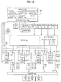
- the Information Collection Architecture invention is shown in a functional block diagram in Fig. 1A which illustrates the control and data flow organization for the invention.
- Each of these four networks 124, 126, 128 and 130 are respectively connected to a second router 140 which then connects to the three destination nodes B1, B2 and B3.
- the router 115 uses the routing table contained therein to establish a logical and/or physical connection between one of the senders A1, A2 or A3 and one of the destinations B1, B2 or B3.
- the routing table shown in Fig. 1A illustrates that the source A1 is connected to the destination B1 over the path P2 which is the FDDI network 126.
- the routing table further provides an interconnection between sender A2 and the destination B2 over the path P1 which is the Token Ring LAN TRLAN 124.
- the routing table shown in Fig. 1A also establishes the connection between the source A3 and the destination B3 over the path P4 which is the Ethernet network 130.
- Network 124 includes nodes N1 to N6 controlled by manager 122A.
- Network 126 includes nodes N7 to N12 controlled by manager 122B.
- Network 128 includes node N13 controlled by manager 122C.
- Network 130 includes nodes N14 to N17 controlled by manager 122D.
- the Information Collection Architecture invention includes the Event Driven Interface (EDI) 120A, that is described in greater detail in Figs. 2A-5, that is connected to the Token Ring LAN 124.
- the Event Driven Interface 120A has been configured by appropriate control vectors C(i) received over the line 142, to perform a customized monitoring of the characteristics of the Token Ring LAN 124.
- the Event Driven Interface 120A outputs event vectors E(i) on line 144 that eventually are used to control the router 115.
- the router 115 in response, will revise its routing table so as to connect the sender A2 to the destination B2 over a different network providing a more optimal communication than that currently provided by the Token Ring LAN 124.
- the manager node 122A shown in Fig. 1A which is connected to the Token Ring LAN 124, can receive control information over line 146 in response to the event vectors E(i) output on line 144 from the Event Driven Interface 120A, to modify the traffic produced by one or more nodes and three on the Token Ring LAN 124, to alleviate the bottleneck condition on the Token Ring LAN 124, thereby enabling the sender A2 to communicate with the destination B2 in a more efficient manner.
- Network 124 is monitored by EDI 120A.
- Network 126 is monitored by EDI 120B.
- Network 128 is monitored by EDI 120C.
- Network 130 is monitored by EDI 120D.
- the architectural diagram of Fig. 1A further shows a data processor 105 consisting of a CPU 20, a memory 100, a network monitor 22, a router interface 24 connected to the router 115, and a printer 26.
- the memory 100 stores programs consisting of a sequence of executable instructions, to perform desired functions when the instructions are executed in the CPU 20. Programs that are included in the memory 100 include the media manager 102, the control vector generator 104, the routing expert 106, the performance expert 108, the security expert 110 and the monitoring expert 112.
- the control vector generator 104 can be a part of the routing expert 106.
- the control generator 104 can be a data file, in one embodiment, which stores predefined control vectors to be downloaded to the EDI 120A.
- control vector generator 104 can be a sequence of program instructions to perform the filter pattern consolidation method shown in the example below.
- the Information Collection Architecture invention includes the control vector generator 104 to access or to generate an appropriate pattern of control vectors C(i) for each respective network 124, 126, 128 and 130 which is to be monitored by a corresponding Event Driven Interface 120A, 120B, 120C or 120D.
- the control vectors C(i) on line 142 are loaded into the Event Driven Interface 120A, to configure the Event Driven Interface 120A to appropriately detect corresponding bit patterns for frames, tokens and other message and control sequences transmitted on the Token Ring LAN 124.
- the Event Driven Interface 120A will then output event vectors E(i) on line 144 which are received by the data processor 105 for analysis by the appropriate expert program.
- the routing expert 106 will perform an analysis of the event vectors E(i) to provide control information which is output on line 146 to the manager node 122A of the Token Ring LAN 124.
- the routing expert 106 will output routing control information through the router interface 124 to the router 115, to modify the routing table shown in Fig. 1A.
- Corresponding operations can be performed with the Event Driven Interface 120B and the manager node 122B for the FDDI network 126 shown in Fig. 1A. Similar operations can be performed with the EDI 120C and the manager node 122C for the ATM network 128. Correspondingly similar operations can be performed with the EDI 120D and the manager node 122D for the Ethernet network 130.
- FIG. 6 shows an overall organizational diagram of the Information Collection Architecture which illustrates that it is comprised of an expert system such as the routing expert 106, and the programmable performance vector generator 121.
- the programmable performance vector generator 121 is an I/O card shown schematically in Fig. 8, which includes the Event Driven Interface 120 connected through a network interface 136 such as a Token Ring interface, to the Token Ring 124.
- Fig. 8 also shows the Event Driven Interface 120, receiving control vectors C(i) through the microchannel interface circuitry 138 and delivering event vectors E(i) to the microchannel interface circuitry 138.
- the programmable performance vector generator card 121 will plug into a workstation such as an IBM Personal Systems/2, upon which may be resident a memory for storing appropriate control vectors C(i).
- the workstation may also store the control vector generator 104 and a routing expert 106 to enable a self-contained Information Collection Architecture invention connected to an individual network, such as the Token Ring LAN 124.
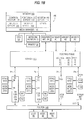
- FIG. 1B shows the Information Collection Architecture invention which was illustrated and discussed in Fig. 1A, in an alternate and preferred embodiment which employs inband control with all communication being carried out through the respective networks 124, 126, 128 and/or 130.
- the programmable performance vector generator (PPVG) card 121 coupled to an appropriate workstation, is connected to its corresponding network, such as the PPVG card 121A, is connected at node N6 to the Token Ring LAN 124.
- the PPRG card 121B is connected to the node N12 of the FDDI network 126.
- the PPVG card 121C is connected to the ATM network 128.
- the PPVG card 121D is connected to the Ethernet network 130.
- the expert system 106 which describes the expert system 106 sending the control vector C(i) to the programmable performance vector generator 121 to configure the Event Driven Interface 120A to collect specified performance parameters for the specified network protocol, in this case the Token Ring LAN 124.
- the PPVG 121A will return event vectors E(i), that contain these performance parameters.
- the expert system 106 will use these parameters to computer the desired network performance matrix and then compare these matrices with those for optimal performance. If poor performance is determined, the expert system can take remedial action, such as outputting a control signal over line 146 to the manager node 122A, to modify the traffic pattern on the Token Ring LAN 124.
- the expert system 106 can output router control information through the router interface 24 to the router 115, to alter the path over which communications are being conducted between a sender node such as A2, and a destination node such as B2.
- Fig. 7 shows a high level flow diagram of the method of operation for the Information Collection Architecture.
- the expert program such as the routing expert 106, will store optimal behavior which would be expected for a particular communications network such as the Token Ring LAN 124, in the information 150 of Fig. 7.
- the optimal behavior information 150 is then compared with the performance process information 152, by the analysis and comparison function 154 of Fig. 7. This is done in conjunction with the knowledge base 156 which will provide a sequence of "IF,” “THEN,” “ELSE” statements which test and compare the performance measurement process information E(i) in 152 with the optimal behavior information in 150.
- the difference between a performance measurement process information 152 and the optimal behavior information 150 is output at 158 as control information which can be applied to either the router 115 or the manager node at 122A in Fig. 1A or to the PPVG card 121A and the manager node 122A in Fig. 1B.
- the Event Driven Interface (EDI) 120 is a versatile, reprogrammable low cost digital filter capable of multiple outputs.
- the filter handles multi-megabit sustained data rates, and performs real time filtering of the incoming data based on multiple patterns which are user definable.
- the digital filter technique is significant because the architectural concepts of the filtering process applied to areas where fast real-time digital filtering is required.
- the EDI is a state-machine which implements a real-time filter built with a few memory modules, a register and clock circuitry. It is programmed by expert 106, which generates the input to the state-machine.
- the EDI 120 digital filter is a state machine which is built with off-the-shelf components and is configured with computer program methods to create the states of the state machine.
- the EDI 120 compares the incoming data from LAN 124, for example, with user defined filter patterns (real time) and if the incoming data matches the user defined filter pattern(s), external output lines 144 are activated. These lines output the event count vectors E(i) or they can be used to cause the storage of the incoming data, the triggering of other devices, the synchronization of external devices, etc.
- a counter 170 can be incremented each time a successful match is made. Several types of patterns can be counted in a corresponding number of counters 170 (see Fig. 9).
- the accumulated counts will then be the vector E(i).
- the filter can be placed in a mode where the external output lines 144 are activated when the incoming data does not match one of the user defined filter patterns.
- the number of filter patterns that can be specified is dependent on the amount of filter memory implemented.
- the EDI digital filter hardware is composed of two elements: a RAM 132 and an address register 134 for the RAM, see Fig. 2A.
- the address register is 'N' bits wide. The most significant bits of the next address of the RAM to be accessed are contained in the N-1 least significant bits of the RAM. Any remaining RAM bits can be used as external outputs from the filter (i.e. one bit is used to indicate if the incoming data matches one of the filter patterns).
- the address register 134 is set to zero to start the filter process.
- the address register is loaded with N-1 bits of output from RAM location zero and one bit of incoming data.
- the incoming data bit becomes the low order bit in the address register.
- These bits (the N-1 bits of the RAM output and the incoming data bit) combine to form the N bit address in the address register to be used for the next "READ" of the RAM 132.
- N-1 bits of the output from the RAM and the incoming data bit are loaded into the address register and the process continues until the filter is halted.
- IGL Infinite Good Loop
- IBL Infinite Bad Loop
- FIG. 2B This process is illustrated in Fig. 2B.
- the values for the 13 (N-1) least significant bits are shown in the filter memory 132.
- the least significant bit is the right-most bit, the most significant bit is the left-most bit, see Fig. 4.
- the contents of RAM location X'3FFC' and X'3FFD' are X'1FFE'.
- IBL Infinite Bad Loop
- the contents of RAM location X'3FFA' and X'3FFB' are X'1FFD'.
- the N-1 (13) bit part of the address that is fed back is always X'1FFD'.
- IGL Infinite Good Loop
- a separate IGL location is provided for every pattern on the network to be counted in one of the counters 170.
- the control vector generation function 104 of the routing expert 106 creates a set of filter patterns using the "Filter Pattern Consolidation Method" feature of this invention, described below. Because ALL filter patterns are compared on a real time basis, they are combined into a consolidated filter pattern (which combines all of the individual filter patterns into one pattern). This consolidation can be thought of as a tree structure with branching from the nodes occurring when an incoming data bit is placed in the N bit address register. The direction of branching is determined by the value of the bit (a one or a zero).
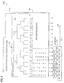
- Fig. 3 illustrates the consolidation of the first five bits of four filter patterns into a filter pattern tree structure, as carried out by the expert 106 in configuring the EDI 120A. The following notes apply to Fig. 3.
- the incoming data bit is placed in the N (14) bit address register with N-1 (13) bits of feedback address from the filter memory.
- This N (14) bit address determines the next N-1 (13) bits of feedback address to be used at the next bit time, this is illustrated in Fig. 4.
- the example received data given in Fig. 4 is Pattern1 in Fig. 3 and is contained in the example memory given in Fig. 2B.
- a method of interpreting the hex numbers under the branches in Fig. 3 is the following: If the N (14) bit address register contains X'0002' (two times the hex value of '0001' given under the first branch) and the incoming data bit (bit 1) is a B'0', the feedback value will be X'0002'. If the incoming data bit (bit 1) is a B'1', the feedback value will be X'0003'.
- the RAM 132 In addition to the N-1 bit output which is fed back to the N bit address register 134 in the digital filter, the RAM 132 also outputs other bits on line 144. These bits can go directly to data processor 105 as the event counts E(i). Or the bits on line 144 in Fig. 2A can be from an individual IGL location in RAM 132, to be counted in a corresponding individual counter 170, as in Fig. 9, to count the occurrence of a corresponding pattern. Or they can also be used to control the storage of trace data, synchronize other devices, increment counters, etc.
- N-1 bits of the filter RAM 132 are fed back to the N bit address register 134, the user can specify the value of additional output bits (external output lines 144) on a bit-by-bit basis in the filter patterns. This is illustrated in Fig. 5. Note that location X'000A' has specified three external output lines to be B'101'. This output will occur on lines 144 when bit three of pattern3 is observed in the incoming data.
- All of the filter patterns are combined into one consolidated pattern using the following method, which is carried out by the control vector generation function 104 of the routing expert 106.
- Each bit in all patterns is consolidated simultaneously, i.e. bit one of every pattern is consolidated, then bit two, etc.
- the following terms and variables are used to illustrate this process:
- the following method is performed by expert 106 to consolidate the filter patterns and is illustrated in the example following the method.
- Parallel (bus type) data can be observed for patterns by serializing the data or by using multiple filters in parallel.
- the external output lines 144 allow virtually unlimited output for event counts E(i), synchronization of devices, for incrementing counters, etc.
- the maximum filter rate is constrained only by the memory access times.
- the filter selects data from a multi-megabit serial data stream.
- Some examples include:
- the expert system 106 characterizes the parameters for each of a variety of network protocols, for example Token Ring, Ethernet, Fiber Data Distributed Interface, System Network Architecture, TCP/IP, SONET, or BISDN, for example.
- the expert system 106 has an analysis portion which performs the analysison the correlated event behavior, as will be described below. Also included is a control section which uses the results of the analysis performed on the correlated event behavior of a network, to output control signals back to the network to control its behavior.
- Fig. 7 is a generalized flow diagram of the data analysis process for the Information Collection Architecture invention. It is carried out by the analysis portion of the expert 106.
- the human activity involved in correcting the behavior of "anything” is a four step process where the successful completion of each step is absolutely fundamental to the success of the activity.
- the logical flow of this performance process is shown in Fig. 7. The steps involved are:
- a simple analysis consists of a comparison of actual vs. optimal behavior. The difference is where we apply our acquired knowledge and experience to effect a repair. The difference in our toaster example is that the bread is not brown on one (the right) side.
- any truly useful analysis tool/program/methodology must deal with all four steps of this analysis process. Analysis success is only met when all four steps of the analysis process have been successfully completed and "answers" are provided in the form of specific recommendations of what to do.
- the PPVG 121 Real-Time Monitor handles the real-time component problem. This monitor must make sure that no "required information" is lost. Thus, the PPVG 121 must be able to inspect all data available on the communications link, no matter how fast it is sent. This component is hardware technology dependent.
- the Programmable Real-Time Variable-Time Interface is a programmable hardware device that screens the real-time data for only that portion of the data required by the network function or service.
- the PRVI also collects screened data, called "information," for the Variable-Time Reporter.
- the type of information collected by the PRVI may be changed "on line” through a programming interface.
- the Variable-Time Reporter sends the "proper time framed information" to the requesting network function or service for performance evaluation, problem determination, monitoring activities, accounting activities,.. etc.
- This information must be sent on demand, but it need not be sent in real-time because most network functions, like performance evaluation, are typically not done in real-time.
- the time frame in which to report the desired information to the network function or service depends on what that function or service will do with the information. For example, decisions dealing with load distribution, load balancing or other dynamic network activity may require information on a second-by-second basis to adequately control the network. It could be disastrous for network behavior to only update this information on a hourly basis. Second-by-second information, however, is of little or no value to capacity planning or accounting programs because much larger time frames are desired.
- the programmable performance vector generator 121 is shown in greater detail in Fig. 8.
- the PPVG card 121 is designed to see all physical media activity. It is not blinded by chip set, hardware, or software limitations. Information capture is accomplished by programming the Event Driven Interface 120 to recognize and collect events at media speed. Finally, the events themselves are organized in a way that is most useful for the service requesting the information. The real key is: do not attempt raw data collection (with all its problems).
- ICA Information Collection Architecture
- One or more expert systems 106 can send input control vectors, C(i), to the PPVG card 121 to configure it to collect events about specific network activities (e.g. protocol behavior).
- the PPVG card will return event vectors, E(i), that contain information concerning these events.
- the expert system 106 will convert these event vectors E(i) to states of a Finite State Machine (FSM).
- FSM Finite State Machine
- the FSM flow allows the computation of the desired network performance measures and then, compare these measures with those for optimal performance. If a performance problem is determined, the expert system 106 can suggest a remedy, present monitored data or control a network control node.
- the PPVG card consists of three main parts: the Event Driven Interface (EDI) 120, the network interface (NI) 136, and microchannel or ESA interface (MI) 138 shown in Fig. 8.
- the event driven detector is the heart of the PPVG card.
- the EDI 120 relies on being programmed by the expert 106 to identify the proper bits that represent an event of interest.
- the EDI 120 will monitor only those network environmental characteristics that are specified by the control vectors C(i) doing the programming of the EDI gate array.
- the EDI will count the number of free tokens to determine utilization and device transmission opportunity. This number is easily countable with today's technology.
- the expert system program 106 supplies input vectors C(i), to identify the events for which we seek information.
- events could be Token Ring MAC frames, Ethernet collisions, FDDI tokens,...etc.
- the expert system 106 will analyze the E(i) vector flow from the PPVG card and send control signals to a network controller 122A. This event vector generation process will be done real-time with no effect on the network performance.
- the expert system 106 uses the parameter counts and applies finite state machine theory in order to derive the desired performance measure, such as the utilization, for each link or node in a particular network environment.
- the expert system 106 can convey any analysis information, along with recommendations for the network service, to the network controller.
- the network controller 122 can use the analysis information to employ a routing algorithm to reallocate resources if necessary and to better understand network behavior and performance.
- the EDI 120 may be implemented via a Field Programmable Gate Array (FPGA) and an external Random Access Memory (RAM).
- the RAM is necessary to implement the tree protocol decoding algorithm.
- the programmability of the RAM or the gate array enables the expert system 106 to send a new C(i) vectors to reconfigure the EDI 120 to accommodate different protocols, i.e., Token Ring, FDDI, Ethernet; and accommodate a variety of different parameter counters depending on the network environment.
- the only constraints to this hardware approach are the speed and depth of the RAM memory 132, and the number of gates and speed of the gate array. Due to the magnitude of data reduction, neither of these pose a major problem.
- the Microchannel Interface (MI) 138 of Fig. 8 provides the PPVG with an interface to the PS/2 microchannel (or other device) over which the PPVG 121 receives the C(i) vector and sends the E(i) vectors.
- the Network Interface (NI) 136 provides the PPVG with an interface to the network.
- the PPVG passively attaches to the ring using the front end (FE) circuitry that is part of a 16 MBPS IBM Token Ring Adapter Card. This circuitry locks onto the analog ring signal and converts it into a digital stream.
- the PPVG also makes use of the digital clock, ready signal and a frequency acquisition signal derived from the analog stream by the FE circuitry. These digital signals will be received onto the PPVG and fed into the EDI 120 via appropriate discrete circuitry.
- the PPVG card attachment to the ring 124 is portrayed in Fig. 1B.
- the main advantage of the PPVG hardware approach is that it provides a real-time, passive, host-transparent way in which to monitor performance parameters.
- This section provides a design overview of a Token Ring (802.5) Media Access Control (MAC) layer analysis expert system 106 designed to employ a PPVG device 121 as the input for its analysis.
- MAC Media Access Control
- the MAC layer controls physical ring media and any station operations that affect the ring. Monitoring (and collecting) MAC activity is necessary to determine both the "health" and the "usage” of the token ring LAN.
- the ICA allows us to determine ring utilization, send control signals to the LAN to alter load balancing and routing, locate and understand errors, answer capacity planning issues, and in general provide any information required about ring activity and operation.
- the 25 MAC frame types provide all the necessary communication for ring management, monitoring, control, and error recovery.
- the MAC layer provides for:
- the ICA approach allows a token ring LAN to be successfully monitored at the MAC layer to provide all the information required to address performance issues and network control.
- the monitoring will be of such a low volume that geographic distance and data correlation problems can be easily addressed.
- An “event” is the occurrence of:
- the event idea is derived from the concept that the activity of all protocols can be described by some finite state machine pattern.
- the collection of one or more events can represent a particular state of protocol activity over some period of time. Events can be considered as elementary building blocks of states. Therefore all states can be identified by one or more events occurring within a specific time period.
- a pattern of events which we call a performance vector, E(i), will be constructed and reported by the Variable Time Reporter. For example, a three event vector can provide an indication of one of many states occurring.
- x and
- y and
- means that STATE P has occurred.
- the PPVG 121 device recognizes one or more simultaneous events by using a real time bit decoding tree in the EDI 120.
- the EDI 120 will recognize any programmed event at media speed.
- the incoming media bit stream is fed into a series storage locations in RAM 132 which are set (via a programmed control vector C(i)) to recognize one or more patterns of bits.
- Multiple event counters 170 are simultaneously updated and organized in an output vector E(i) which is returned at the appropriate frequency for one or more services.
- An example of this output vector is E(i), shown next. Where the value i could be a count of vectors returned.
- E(i) (
- Event vectors could be returned to monitor ring activity for problem determination reasons on network control.
- an E(i) vector could be a series of counters for all MAC frame types.
- E(i) (
- the relationships between the event counts can represent the occurrence of a specific ring problem. These relationships can be viewed as a "statistical signature" of a particular token ring problem. These signatures can be recognized and diagnosed by the routing expert 106. Appropriate network control signals can be output by routing expert 106 to router 115 or manager 122A in the network, in response.
- ICA consists of two categories of vectors: Control vectors and Event vectors.
- Control vectors are designated C(i) and event vectors are designated E(i).
- Two types of event vectors are defined.
- An E(0) vector and an E(i) vector where i 1,2,3...etc.
- the E(0) vector provides static one time information that is unlikely to change over time (such as the number of devices on the ring, ring latency,...etc.).
- the E(i) vectors provide variable event count information which will change considerably (due to changing network activity).
- the E(i) vectors for token ring MAC layer activity can be structured with the following event counters:
- E(i) (#T,#F,MAXF,MINF,MFR,#M, FC bar, AR bar,#B)
- E(i) (#T,#F,MAXF,MINF,MFR,#M, FC bar,P4,#R)
- Other event vectors can be developed if required.
- the event vectors generated are a result of the "programming" in the C(i) vector by expert system 106.
- new events can be defined by the relationship between events in the same vector. For example, the average number of frames between tokens is simply #F divided by #T. This information can be constructed within the expert system 106.
- Other events can represent "frequency" relationships between events. For (hypothetical) example, a counter increments whenever event A occurs three times without event B occurring.
- Any expert system 106 derived conclusions can be sent to any network controller 122A or 115 via alerts or messages.
- the total ICA process can be done real-time with no effect on the network performance.
- Other programs in memory 100 can use the event counts in conjunction with finite state machine theory to derive other desired performance measures and network control not included as events in the E(i) vectors (such as utilization).
- Expert system 106 can convey information, along with recommendations for a network service, to the network controller 122A or the network router 115.
- the router 115 can use the information to employ a routing algorithm to reallocate resources if necessary or to better control, monitor and understand network behavior and performance.
- the MAC layer token ring expert system 106 detects four primary states.
- the four primary states are:
- token ring (802.5) MAC expert system 106 can be directly applied to FDDI MAC activity.
- the same FSM may be appropriate for FDDI as well as token ring.
- a "generic ring FSM" can be constructed for all rings with only the heuristic tests modified for different ring protocols.
- a FDDI expert system 106' is a straightforward and natural extension of our token ring expert system 106.
- Ethernet and 802.3 LANs can be analyzed and diagnosed by expert 106 using the same event and FSM approaches.
- the number of collision events along with other events such as the number of frames transferred can provide load and bus availability information. Other events are easily defined to provide additional information. Contention protocols such as Ethernet require fewer events to understand their behavior and thus are easier to analyze with the ICA approach.
- C(i) vectors from a expert system(s) can program the PPVG 121 hardware to look for a series of events from multiple protocols simultaneously (a vertical slice of the protocol stack). In this way, it is possible to do an analysis or a "health check" of the whole protocol stack, simultaneously.
- ICA ICA is an extremely flexible, totally protocol independent information capture "enabler.” With the ICA techniques the expert system 106 can easily look into "protocol stacks" or recursively enveloped stacks to find protocol problems.
- Fig. 10 is a flow diagram of the method for the Information Collection Architecture invention.
- Step 402 outputs from the router expert 106, a control vector C(i) to the event driven interface (EDI) 120A.
- step 104 has the routing expert 106 wait for the EDI 120A to respond.
- Step 406 receives the response from the EDI 120A, which is an event vector E(i).
- step 408 has the routing expert 106 compute the network performance measure.
- a high usage state can be analyzed by monitoring the number of frames and the number of tokens per unit time.
- step 410 compares the performance measure with the user's desired optimal or predefined performance. For example, if the user predefines that if the number of frames is twice the number of tokens then the ring is considered in a high usage state, then this predefined value is included in the router expert 106. The comparison between the computed value and the desired value is then performed in step 410.
- Step 412 has the routing expert 106 then issue a control signal on line 146 to the node manager 122 for the LAN 124, or alternately to the router 115, to change the network routing parameters in order to bring the token ring LAN 124 closer to the performance characteristics desired by the user.
- ICA represents a new and unique approach to providing real-time network environment and activity information.
- the ICA technique examines the characteristics of the communications channel in order to reduce to a small fraction the amount of data required to accomplish real-time network functions and services.
- our technique will be applicable to all types of network functions and services that require information collection, not just real-time services. The main advantages are as follows:
- ICA is determining the proper communications channel characteristics to monitor in order to maximize the information content, for a function or service, while minimizing data collection. This demands the extreme monitoring flexibility that ICA provides. ICA is appropriate for existing networks and future very high speed networks.
- ICA information can be directly used for performance analysis, network control, problem determination, and capacity planning without the need for post-processing, e.g., decompression or reconstruction. Furthermore, performance results derived, using the ICA technique, are at least as accurate as those obtained from existing performance measurement methods.
- the Information Collection Architecture invention can be applied to other types of systems besides digital data communications systems. For example, it can be applied to a body of digital data contained in the data base.
- the data base contains at least one unit of data which is organized under a data base organization scheme which has a characteristic data pattern which can be identified by the Event Driven Interface.
- a suitable control vector would be applied to the Event Driven Interface to filter trap and count the characteristic pattern of the data unit desired to be counted. Counting such data units can then be used to characterize the overall organization of the data base.
Landscapes
- Engineering & Computer Science (AREA)
- Computer Networks & Wireless Communication (AREA)
- Signal Processing (AREA)
- Data Exchanges In Wide-Area Networks (AREA)
- Maintenance And Management Of Digital Transmission (AREA)
Applications Claiming Priority (2)
| Application Number | Priority Date | Filing Date | Title |
|---|---|---|---|
| US24575 | 1993-03-01 | ||
| US08/024,575 US5365514A (en) | 1993-03-01 | 1993-03-01 | Event driven interface for a system for monitoring and controlling a data communications network |
Publications (2)
| Publication Number | Publication Date |
|---|---|
| EP0614295A2 true EP0614295A2 (fr) | 1994-09-07 |
| EP0614295A3 EP0614295A3 (fr) | 1995-08-02 |
Family
ID=21821305
Family Applications (1)
| Application Number | Title | Priority Date | Filing Date |
|---|---|---|---|
| EP94101188A Withdrawn EP0614295A3 (fr) | 1993-03-01 | 1994-01-27 | Interface commandé par des évènements pour un système de surveillance et de commande d'un réseau de communication de données. |
Country Status (4)
| Country | Link |
|---|---|
| US (1) | US5365514A (fr) |
| EP (1) | EP0614295A3 (fr) |
| JP (1) | JP2644179B2 (fr) |
| CA (1) | CA2110142C (fr) |
Cited By (3)
| Publication number | Priority date | Publication date | Assignee | Title |
|---|---|---|---|---|
| EP0841774A3 (fr) * | 1996-09-13 | 2000-08-09 | Digital Vision Laboratories Corporation | Procédé pour le contrôle d'une voie de communication dans un réseau de communications |
| ES2159249A1 (es) * | 1999-08-17 | 2001-09-16 | Univ Navarra Publica | Sistema de monitorizacion de redes de comunicaciones empleando un metodo jerarquico de analisis de trafico y almacenamiento de medidas de trafico. |
| CN114385387A (zh) * | 2022-03-23 | 2022-04-22 | 恒生电子股份有限公司 | 访问信息生成方法、装置和计算机设备 |
Families Citing this family (70)
| Publication number | Priority date | Publication date | Assignee | Title |
|---|---|---|---|---|
| US5375070A (en) | 1993-03-01 | 1994-12-20 | International Business Machines Corporation | Information collection architecture and method for a data communications network |
| US5493689A (en) * | 1993-03-01 | 1996-02-20 | International Business Machines Corporation | System for configuring an event driven interface including control blocks defining good loop locations in a memory which represent detection of a characteristic pattern |
| US5557747A (en) * | 1993-06-22 | 1996-09-17 | Rogers; Lawrence D. | Network policy implementation system for performing network control operations in response to changes in network state |
| US5446874A (en) * | 1993-12-23 | 1995-08-29 | International Business Machines Corp. | Automated benchmarking with self customization |
| US5544077A (en) * | 1994-01-19 | 1996-08-06 | International Business Machines Corporation | High availability data processing system and method using finite state machines |
| EP0669736A3 (fr) * | 1994-01-26 | 1997-01-08 | Ibm | Routage dynamique en temps réel dans un réseau de données. |
| US5526283A (en) * | 1994-01-26 | 1996-06-11 | International Business Machines Corporation | Realtime high speed data capture in response to an event |
| JP2669604B2 (ja) * | 1994-01-26 | 1997-10-29 | インターナショナル・ビジネス・マシーンズ・コーポレイション | 位置決定方法および装置 |
| US5500855A (en) * | 1994-01-26 | 1996-03-19 | International Business Machines Corporation | Realtime event classification for a data communications network |
| US5483637A (en) * | 1994-06-27 | 1996-01-09 | International Business Machines Corporation | Expert based system and method for managing error events in a local area network |
| US5493562A (en) * | 1994-11-10 | 1996-02-20 | Lo; William | Apparatus and method for selectively storing error statistics |
| US5802041A (en) * | 1995-05-31 | 1998-09-01 | International Business Machines Corporation | Monitoring ethernet lans using latency with minimum information |
| US5629927A (en) * | 1995-05-31 | 1997-05-13 | International Business Machines Corporation | Monitoring ATM networks for burstiness using cell full or cell empty latency with minimum information |
| US5615135A (en) * | 1995-06-01 | 1997-03-25 | International Business Machines Corporation | Event driven interface having a dynamically reconfigurable counter for monitoring a high speed data network according to changing traffic events |
| US5657315A (en) * | 1995-06-01 | 1997-08-12 | International Business Machines Corporation | System and method for ring latency measurement and correction |
| US5802302A (en) * | 1995-06-29 | 1998-09-01 | International Business Machines Corporation | System and method for response time measurement in high speed data transmission networks |
| US5787086A (en) | 1995-07-19 | 1998-07-28 | Fujitsu Network Communications, Inc. | Method and apparatus for emulating a circuit connection in a cell based communications network |
| AU6970896A (en) | 1995-09-14 | 1997-04-01 | Ascom Nexion Inc. | Transmitter controlled flow control for buffer allocation in wide area atm networks |
| JP3426428B2 (ja) * | 1995-10-27 | 2003-07-14 | 富士通株式会社 | トランザクションのトレース装置 |
| AU1697697A (en) | 1996-01-16 | 1997-08-11 | Fujitsu Limited | A reliable and flexible multicast mechanism for atm networks |
| US6237029B1 (en) | 1996-02-26 | 2001-05-22 | Argosystems, Inc. | Method and apparatus for adaptable digital protocol processing |
| US5860024A (en) * | 1996-04-15 | 1999-01-12 | Advanced Micro Devices, Inc. | Microprocessor with automatic name generation including performance indication |
| US5771395A (en) * | 1996-04-22 | 1998-06-23 | Lockheed Martin Corporation | System for processing information from scanned documents using event driven interface with patterns loaded in RAM and with address generator for addressing bit patterns |
| US5933602A (en) * | 1996-07-31 | 1999-08-03 | Novell, Inc. | System for selecting command packet and corresponding response packet from communication stream of packets by monitoring packets sent between nodes on network |
| US5748905A (en) | 1996-08-30 | 1998-05-05 | Fujitsu Network Communications, Inc. | Frame classification using classification keys |
| US5682328A (en) * | 1996-09-11 | 1997-10-28 | Bbn Corporation | Centralized computer event data logging system |
| US5913041A (en) * | 1996-12-09 | 1999-06-15 | Hewlett-Packard Company | System for determining data transfer rates in accordance with log information relates to history of data transfer activities that independently stored in content servers |
| US6578077B1 (en) | 1997-05-27 | 2003-06-10 | Novell, Inc. | Traffic monitoring tool for bandwidth management |
| US6016310A (en) * | 1997-06-30 | 2000-01-18 | Sun Microsystems, Inc. | Trunking support in a high performance network device |
| US6246680B1 (en) | 1997-06-30 | 2001-06-12 | Sun Microsystems, Inc. | Highly integrated multi-layer switch element architecture |
| US6119196A (en) * | 1997-06-30 | 2000-09-12 | Sun Microsystems, Inc. | System having multiple arbitrating levels for arbitrating access to a shared memory by network ports operating at different data rates |
| US6049528A (en) * | 1997-06-30 | 2000-04-11 | Sun Microsystems, Inc. | Trunking ethernet-compatible networks |
| US6115378A (en) * | 1997-06-30 | 2000-09-05 | Sun Microsystems, Inc. | Multi-layer distributed network element |
| US6094435A (en) * | 1997-06-30 | 2000-07-25 | Sun Microsystems, Inc. | System and method for a quality of service in a multi-layer network element |
| US6081522A (en) * | 1997-06-30 | 2000-06-27 | Sun Microsystems, Inc. | System and method for a multi-layer network element |
| US6081512A (en) * | 1997-06-30 | 2000-06-27 | Sun Microsystems, Inc. | Spanning tree support in a high performance network device |
| US6044087A (en) * | 1997-06-30 | 2000-03-28 | Sun Microsystems, Inc. | Interface for a highly integrated ethernet network element |
| US6088356A (en) * | 1997-06-30 | 2000-07-11 | Sun Microsystems, Inc. | System and method for a multi-layer network element |
| US6044418A (en) * | 1997-06-30 | 2000-03-28 | Sun Microsystems, Inc. | Method and apparatus for dynamically resizing queues utilizing programmable partition pointers |
| US6021132A (en) * | 1997-06-30 | 2000-02-01 | Sun Microsystems, Inc. | Shared memory management in a switched network element |
| US6049764A (en) * | 1997-11-12 | 2000-04-11 | City Of Hope | Method and system for real-time control of analytical and diagnostic instruments |
| US6681315B1 (en) | 1997-11-26 | 2004-01-20 | International Business Machines Corporation | Method and apparatus for bit vector array |
| US6347382B1 (en) * | 1998-11-30 | 2002-02-12 | Advantest Corp. | Multi-port device analysis apparatus and method |
| US6608819B1 (en) | 1999-01-12 | 2003-08-19 | Mcdata Corporation | Method for scoring queued frames for selective transmission through a switch |
| US7382736B2 (en) | 1999-01-12 | 2008-06-03 | Mcdata Corporation | Method for scoring queued frames for selective transmission through a switch |
| US6449255B1 (en) | 1999-04-26 | 2002-09-10 | Cisco Technology, Inc. | Method and apparatus for managing packets using a real-time feedback signal |
| US7185081B1 (en) | 1999-04-30 | 2007-02-27 | Pmc-Sierra, Inc. | Method and apparatus for programmable lexical packet classifier |
| US7188168B1 (en) | 1999-04-30 | 2007-03-06 | Pmc-Sierra, Inc. | Method and apparatus for grammatical packet classifier |
| US6542854B2 (en) * | 1999-04-30 | 2003-04-01 | Oracle Corporation | Method and mechanism for profiling a system |
| US6691146B1 (en) | 1999-05-19 | 2004-02-10 | International Business Machines Corporation | Logical partition manager and method |
| US6681240B1 (en) | 1999-05-19 | 2004-01-20 | International Business Machines Corporation | Apparatus and method for specifying maximum interactive performance in a logical partition of a computer system independently from the maximum interactive performance in other partitions |
| US6467007B1 (en) | 1999-05-19 | 2002-10-15 | International Business Machines Corporation | Processor reset generated via memory access interrupt |
| US6279046B1 (en) * | 1999-05-19 | 2001-08-21 | International Business Machines Corporation | Event-driven communications interface for logically-partitioned computer |
| US6959291B1 (en) | 1999-05-19 | 2005-10-25 | International Business Machines Corporation | Management of a concurrent use license in a logically-partitioned computer |
| US7171464B1 (en) * | 1999-06-23 | 2007-01-30 | Microsoft Corporation | Method of tracing data traffic on a network |
| WO2001001272A2 (fr) | 1999-06-30 | 2001-01-04 | Apptitude, Inc. | Procede et appareil permettant de surveiller le trafic dans un reseau |
| US6771646B1 (en) | 1999-06-30 | 2004-08-03 | Hi/Fn, Inc. | Associative cache structure for lookups and updates of flow records in a network monitor |
| US6789116B1 (en) * | 1999-06-30 | 2004-09-07 | Hi/Fn, Inc. | State processor for pattern matching in a network monitor device |
| US7263558B1 (en) | 1999-09-15 | 2007-08-28 | Narus, Inc. | Method and apparatus for providing additional information in response to an application server request |
| FI114749B (fi) * | 2000-09-11 | 2004-12-15 | Nokia Corp | Poikkeamien ilmaisujärjestelmä ja menetelmä sen opettamiseksi |
| US20020057592A1 (en) * | 2000-11-13 | 2002-05-16 | Robb David C. | Distributed storage in semiconductor memory systems |
| US9917883B2 (en) | 2002-06-13 | 2018-03-13 | Throughputer, Inc. | Direct binary file transfer based network management system free of messaging, commands and data format conversions |
| US7324460B2 (en) | 2002-11-28 | 2008-01-29 | International Business Machines Corporation | Event-driven flow control for a very high-speed switching node |
| US7222072B2 (en) * | 2003-02-13 | 2007-05-22 | Sbc Properties, L.P. | Bio-phonetic multi-phrase speaker identity verification |
| US20060036720A1 (en) * | 2004-06-14 | 2006-02-16 | Faulk Robert L Jr | Rate limiting of events |
| US7719965B2 (en) * | 2004-08-25 | 2010-05-18 | Agilent Technologies, Inc. | Methods and systems for coordinated monitoring of network transmission events |
| US7573833B2 (en) | 2005-04-21 | 2009-08-11 | Cisco Technology, Inc. | Network presence status from network activity |
| US9225732B2 (en) * | 2011-11-29 | 2015-12-29 | Georgia Tech Research Corporation | Systems and methods for fingerprinting physical devices and device types based on network traffic |
| US10498585B2 (en) | 2015-10-16 | 2019-12-03 | Walmart Apollo, Llc | Sensor data analytics and alarm management |
| US10732974B2 (en) * | 2016-05-05 | 2020-08-04 | Walmart Apollo, Llc | Engine agnostic event monitoring and predicting systems and methods |
Family Cites Families (32)
| Publication number | Priority date | Publication date | Assignee | Title |
|---|---|---|---|---|
| US4227245A (en) * | 1972-06-01 | 1980-10-07 | Westinghouse Electric Corp. | Digital computer monitored system or process which is configured with the aid of an improved automatic programming system |
| US4241402A (en) | 1978-10-12 | 1980-12-23 | Operating Systems, Inc. | Finite state automaton with multiple state types |
| US4459656A (en) * | 1981-10-01 | 1984-07-10 | Honeywell Information Systems Inc. | Clocking system for a computer performance monitoring device |
| US4521849A (en) * | 1981-10-01 | 1985-06-04 | Honeywell Information Systems Inc. | Programmable hit matrices used in a hardware monitoring interface unit |
| US4458309A (en) * | 1981-10-01 | 1984-07-03 | Honeywell Information Systems Inc. | Apparatus for loading programmable hit matrices used in a hardware monitoring interface unit |
| JPS5981738A (ja) * | 1982-11-01 | 1984-05-11 | Fujitsu Ltd | 状態管理方式 |
| JPH0710069B2 (ja) * | 1984-08-23 | 1995-02-01 | 日本電信電話株式会社 | パケット通信システム |
| US4805089A (en) * | 1985-04-30 | 1989-02-14 | Prometrix Corporation | Process control interface system for managing measurement data |
| US4779194A (en) * | 1985-10-15 | 1988-10-18 | Unisys Corporation | Event allocation mechanism for a large data processing system |
| US5062055A (en) * | 1986-09-02 | 1991-10-29 | Digital Equipment Corporation | Data processor performance advisor |
| JPS6367383A (ja) * | 1986-09-09 | 1988-03-26 | 桐生 三男 | 地上構造物の雪処理装置 |
| US4980824A (en) * | 1986-10-29 | 1990-12-25 | United Technologies Corporation | Event driven executive |
| CA1280217C (fr) * | 1987-06-01 | 1991-02-12 | Stephen R.H. Hardy | Methode et appareil d'utilisation de stations a deux temps d'attemte pour ameliorer la performance des reseaux en anneau a jeton |
| US4851998A (en) * | 1987-06-03 | 1989-07-25 | I/O Xel, Inc. | Method for analyzing performance of computer peripherals |
| US4887076A (en) * | 1987-10-16 | 1989-12-12 | Digital Equipment Corporation | Computer interconnect coupler for clusters of data processing devices |
| US4905171A (en) * | 1987-11-09 | 1990-02-27 | International Business Machines Corporation | Workstation controller performance monitor |
| US5072376A (en) * | 1988-06-10 | 1991-12-10 | Amdahl Corporation | Measuring utilization of processor shared by multiple system control programs |
| US5035302A (en) * | 1989-03-03 | 1991-07-30 | Otis Elevator Company | "Artificial Intelligence" based learning system predicting "Peak-Period" times for elevator dispatching |
| US5067107A (en) * | 1988-08-05 | 1991-11-19 | Hewlett-Packard Company | Continuous computer performance measurement tool that reduces operating system produced performance data for logging into global, process, and workload files |
| JPH0245832A (ja) * | 1988-08-08 | 1990-02-15 | Nippon Telegr & Teleph Corp <Ntt> | オペレーションエキスパートシステム |
| US4939724A (en) * | 1988-12-29 | 1990-07-03 | Intel Corporation | Cluster link interface for a local area network |
| JPH0734562B2 (ja) * | 1989-02-09 | 1995-04-12 | 日本電信電話株式会社 | プロトコル故障検出方法 |
| US5125098A (en) | 1989-10-06 | 1992-06-23 | Sanders Associates, Inc. | Finite state-machine employing a content-addressable memory |
| JPH03131176A (ja) * | 1989-10-16 | 1991-06-04 | Victor Co Of Japan Ltd | 木構造可変長符号の復号方式 |
| EP0431232A1 (fr) * | 1989-12-06 | 1991-06-12 | International Business Machines Corporation | Mécanisme de mesure des durées d'utilisation des composants logicielles et matérielles dans des systèmes complexes |
| US5079760A (en) * | 1990-02-06 | 1992-01-07 | Paul Nemirovsky | Method for efficient distributed data communications network access network configuration |
| US5214780A (en) * | 1990-03-23 | 1993-05-25 | Sun Microsystems, Inc. | Synchronized journaling system |
| JPH0413338A (ja) * | 1990-05-01 | 1992-01-17 | Mitsubishi Electric Corp | 特定ビット含有率検出回路 |
| US5198805A (en) * | 1990-09-04 | 1993-03-30 | Hewlett-Packard Company | Method and apparatus for monitoring a network and locating a node using signal strength calculations |
| JPH04245395A (ja) * | 1991-01-31 | 1992-09-01 | Fuji Electric Co Ltd | プログラム制御方法 |
| US5223827A (en) * | 1991-05-23 | 1993-06-29 | International Business Machines Corporation | Process and apparatus for managing network event counters |
| EP0591593A1 (fr) * | 1992-10-09 | 1994-04-13 | International Business Machines Corporation | Dispositif et méthode de gestion d'événements asynchrones dans une machine à nombre fini d'états |
-
1993
- 1993-03-01 US US08/024,575 patent/US5365514A/en not_active Expired - Fee Related
- 1993-11-26 CA CA002110142A patent/CA2110142C/fr not_active Expired - Fee Related
-
1994
- 1994-01-25 JP JP6006301A patent/JP2644179B2/ja not_active Expired - Lifetime
- 1994-01-27 EP EP94101188A patent/EP0614295A3/fr not_active Withdrawn
Cited By (3)
| Publication number | Priority date | Publication date | Assignee | Title |
|---|---|---|---|---|
| EP0841774A3 (fr) * | 1996-09-13 | 2000-08-09 | Digital Vision Laboratories Corporation | Procédé pour le contrôle d'une voie de communication dans un réseau de communications |
| ES2159249A1 (es) * | 1999-08-17 | 2001-09-16 | Univ Navarra Publica | Sistema de monitorizacion de redes de comunicaciones empleando un metodo jerarquico de analisis de trafico y almacenamiento de medidas de trafico. |
| CN114385387A (zh) * | 2022-03-23 | 2022-04-22 | 恒生电子股份有限公司 | 访问信息生成方法、装置和计算机设备 |
Also Published As
| Publication number | Publication date |
|---|---|
| CA2110142A1 (fr) | 1994-09-02 |
| US5365514A (en) | 1994-11-15 |
| JP2644179B2 (ja) | 1997-08-25 |
| CA2110142C (fr) | 1998-04-21 |
| EP0614295A3 (fr) | 1995-08-02 |
| JPH06291765A (ja) | 1994-10-18 |
Similar Documents
| Publication | Publication Date | Title |
|---|---|---|
| US5365514A (en) | Event driven interface for a system for monitoring and controlling a data communications network | |
| US5375070A (en) | Information collection architecture and method for a data communications network | |
| US5493689A (en) | System for configuring an event driven interface including control blocks defining good loop locations in a memory which represent detection of a characteristic pattern | |
| US5974457A (en) | Intelligent realtime monitoring of data traffic | |
| EP0613270B1 (fr) | Méthode d'analyse de réseau | |
| Papagiannaki et al. | Measurement and analysis of single-hop delay on an IP backbone network | |
| US5446874A (en) | Automated benchmarking with self customization | |
| US8391157B2 (en) | Distributed flow analysis | |
| US7636320B1 (en) | System and method for creating an asynchronous transfer mode port mirror | |
| US6885641B1 (en) | System and method for monitoring performance, analyzing capacity and utilization, and planning capacity for networks and intelligent, network connected processes | |
| US7813338B2 (en) | System and method for analyzing asynchronous transfer mode communications | |
| US7568023B2 (en) | Method, system, and data structure for monitoring transaction performance in a managed computer network environment | |
| US20020039352A1 (en) | Methods, systems, and computer program products for managing a service provided by a network | |
| US20040240387A1 (en) | System and method for simulating traffic loads in packetized communication networks | |
| WO2001041361A1 (fr) | Procede et dispositif d'analyse des performances de reseaux de donnees | |
| JPH07221760A (ja) | データ捕獲装置 | |
| WO1999063439A1 (fr) | Appareil et procede permettant de tester des applications reseau | |
| CN109831462A (zh) | 一种病毒检测方法及装置 | |
| Chen | Increasing the observability of Internet behavior | |
| Polverini et al. | Reducing the in band network telemetry overhead through the spatial sampling: Theory and experimental results | |
| US20030225877A1 (en) | Method and apparatus of diagnosing network performance issues through correlative analysis | |
| US6084860A (en) | Method for determining the drop rate, the transit delay and the break state of communications objects | |
| WO1998047308A1 (fr) | Essai de reseau | |
| US6584072B1 (en) | Method for determining the drop rate, the transit delay, and the break state of communications objects | |
| Sardellitti et al. | In band network telemetry overhead reduction based on data flows sampling and recovering |
Legal Events
| Date | Code | Title | Description |
|---|---|---|---|
| PUAI | Public reference made under article 153(3) epc to a published international application that has entered the european phase |
Free format text: ORIGINAL CODE: 0009012 |
|
| AK | Designated contracting states |
Kind code of ref document: A2 Designated state(s): DE FR GB |
|
| 17P | Request for examination filed |
Effective date: 19950117 |
|
| PUAL | Search report despatched |
Free format text: ORIGINAL CODE: 0009013 |
|
| AK | Designated contracting states |
Kind code of ref document: A3 Designated state(s): DE FR GB |
|
| 17Q | First examination report despatched |
Effective date: 19990511 |
|
| STAA | Information on the status of an ep patent application or granted ep patent |
Free format text: STATUS: THE APPLICATION IS DEEMED TO BE WITHDRAWN |
|
| 18D | Application deemed to be withdrawn |
Effective date: 20000801 |