EP0614713B1 - Elektromagnetische Bremsvorrichtung für eine Stranggiessform - Google Patents
Elektromagnetische Bremsvorrichtung für eine Stranggiessform Download PDFInfo
- Publication number
- EP0614713B1 EP0614713B1 EP93103780A EP93103780A EP0614713B1 EP 0614713 B1 EP0614713 B1 EP 0614713B1 EP 93103780 A EP93103780 A EP 93103780A EP 93103780 A EP93103780 A EP 93103780A EP 0614713 B1 EP0614713 B1 EP 0614713B1
- Authority
- EP
- European Patent Office
- Prior art keywords
- casting mold
- support frame
- braking apparatus
- electromagnetic braking
- core
- Prior art date
- Legal status (The legal status is an assumption and is not a legal conclusion. Google has not performed a legal analysis and makes no representation as to the accuracy of the status listed.)
- Expired - Lifetime
Links
Images


Classifications
-
- B—PERFORMING OPERATIONS; TRANSPORTING
- B22—CASTING; POWDER METALLURGY
- B22D—CASTING OF METALS; CASTING OF OTHER SUBSTANCES BY THE SAME PROCESSES OR DEVICES
- B22D11/00—Continuous casting of metals, i.e. casting in indefinite lengths
- B22D11/10—Supplying or treating molten metal
- B22D11/11—Treating the molten metal
- B22D11/114—Treating the molten metal by using agitating or vibrating means
- B22D11/115—Treating the molten metal by using agitating or vibrating means by using magnetic fields
Definitions
- the present invention relates to an electromagnetic braking apparatus for controlling molten steel flowing down in a casting mold by applying a static electromagnetic field to the molten steel supplied from a submerged nozzle into the casting mold, in the continuous casting of the molten steel.
- a method of controlling molten steel flowing down in a casting mold by applying a static electromagnetic field to the molten steel supplied into the casting mold is effective to gather and catch inclusions and prevent the entrapment of powders and bubbles when killed steel and in particular low carbon Al killed steel is continuously cast at a high speed.
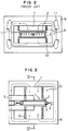
- Electromagnetic braking apparatuses used to this method are disclosed in Japanese Patent Examined Publication No. 2-20349 and Japanese Patent Unexamined Publication No. 2-284750 and generally have the arrangement shown in Figures 1 and 2.
- a casting mold 1 with a rectangular cross section has wide side walls 2 and narrow end walls 3.
- An electromagnet 10 is disposed along each of the side walls 2 and has a core 7 and coil 8 wound around the core 7.
- a magnetic path forming iron core 13 is connected to ends of the cores 7 and extends to surround the casting mold 1 to thereby constitute an electromagnet device for applying a static electromagnetic field in the direction across the side walls 2 of the casting mold 1.
- the electromagnet device is mounted on the support frame 6 disposed on a vibration table 9.
- the support frame 6 further supports a cooling box 5 for cooling the casting mold 1 and width changing device 4 for changing the width of the casting mold by moving the end walls 3 of the casting mold.
- the magnetic path forming iron core 13 has a reduced thickness at the portion thereof to be interfered with the width changing device 4 and support frame 6 to prevent the interference with these components. Further, the corner of the magnetic path forming iron core 13 is chamfered to prevent the interference with water pipes 11 connected to the cooling boxes. Further, an opening, through which the magnetic path forming iron core 13 passes, is defined to the cooling box so that the magnetic path forming iron core 13 extends to surround the casting mold and the electromagnet.
- the electromagnet device must reduce the magnetic resistance of the magnet path forming iron core to effectively produce a static electromagnetic field.
- the magnetic path forming iron core preferably has a large cross sectional area. Nevertheless, since the magnetic path forming iron core of the conventional electromagnetic braking apparatuses has a portion with a reduced cross sectional area to prevent the interference with other components such as the support frame, width changing device, duct and the like, the electromagnetic braking apparatus cannot produce a magnetic flux density of about 2000 - 5000 Gauss at the center of the casting mold.
- an electromagnetic device capable of producing the above magnetic flux density is provided by using an magnetic path forming iron core having a portion with a reduced cross sectional area
- the weight of the magnetic path forming iron core is increased and thus the size of a support frame for supporting it is also increased.
- a crane associated with a vibration device and continuous casting mold and a motor for the vibration device must has an increased capacity.
- another problem arises in that since the large magnetic path forming iron core extends through a cooling box, the flow of a coolant in the cooling box is obstructed.
- an object of the present invention is to provide an electromagnetic braking apparatus for a continuous casting mold capable of producing a magnetic flux density of about 2000 - 5000 Gauss at the center of the casting mold without increasing the weight of the continuous casting mold.
- An electromagnetic braking apparatuses for a continuous casting mold with a rectangular cross section including wide side walls and narrow end walls; according to the present invention comprises electromagnets each of which comprises a core disposed along the side wall of the casting mold and a coil wound around the core for applying a static electromagnetic field in the direction across the side walls of the casting mold; and a support frame for supporting a width changing means for changing the width of the casting mold and cooling boxes for cooling the casting mold, the support frame extending to surround the casting mold and the electromagnets and connected to the cores of the electromagnets to thereby form the magnetic path of the electromagnets.
- the core may be integrally connected to the support frame or detachably connected thereto.
- the support frame is preferably composed of a ferromagnetic material. Further, the support frame preferably has a cross sectional area sufficient to produce a magnetic flux density of 2000 - 5000 Gauss at the center of the casting mold.
- the coil is wound around the core over the distance between the side walls and the support frame.
- the support frame supporting the width changing means also serves as the magnetic path forming iron core of the electromagnets, a conventional magnetic path forming iron core is not needed.
- the size of the electromagnet can be increased as well as the cross sectional area of the support frame can be increased, without increasing the weight of the continuous casting mold, and thus a magnetic flux density of 2000 - 5000 Gauss can be produced at the center of the casting mold.
- the capacity of a vibration device and crane can be reduced. Furthermore, the flow of a coolant in the cooling box is not obstructed.
- Figures 1 and 2 show a conventional electromagnetic braking apparatus for a continuous casting mold, wherein:
- a casting mold 1 with a rectangular cross section includes with side walls 2 and narrow end walls 3. Electromagnets 10 are disposed along the side walls 2 and have cores 7 and coils 8 would around the cores 7.
- a support frame 6 is disposed on a vibration table 9 and supports cooling boxes 5 for cooling the casting mold 1 and a width changing device for changing the width of the casting mold by moving the end walls 3 of the casting mold.
- the end of the core 7 is integrally or detachably connected to the support frame 6 and the coil 8 is wound around the core 7 over the distance between the side wall 2 and the support frame 6.
- the support frame 6 extends to surround the casting mold 1 and electromagnets 10 and is composed of a ferromagnetic material.
- the support member 6 has a cross sectional area sufficient to produce a magnetic flux density of about 2000 - 5000 Gauss at the center of the casting mold.
Landscapes
- Engineering & Computer Science (AREA)
- Mechanical Engineering (AREA)
- Continuous Casting (AREA)
Claims (6)
- Elektromagnetische Bremsvorrichtung für eine Stranggußform (1) mit einem rechtwinkligen Querschnitt mit breiten Seitenwänden (2) und schmalen Endwänden (3), die aufweist:Elektromagneten (10) mit jeweils einem längs der Seitenwand der Gußform angeordneten Kern (7) und einer um den Kern gewickelten Spule (8) zum Anlegen eines statischen elektromagnetischen Felds in Querrichtung zu den Seitenwänden der Gußform (1); undeinen Stützrahmen (6) zum Stützen einer Breitenänderungseinrichtung (4) zum Ändern der Breite der Gußform (1) und von Kühlkästen (5) zum Kühlen der Gußform (1), wobei der Stützrahmen (6) so verläuft, daß er die Gußform (1) und die Elektromagneten (10) umgibt, und mit den Kernen (7) der Elektromagneten (10) verbunden ist, um dadurch den magnetischen Kreis der Elektromagneten (10) zu bilden.
- Elektromagnetische Bremsvorrichtung nach Anspruch 1, wobei der Kern (7) in einem Stück mit dem Stützrahmen (6) verbunden ist.
- Elektromagnetische Bremsvorrichtung nach Anspruch 1, wobei der Kern (7) lösbar mit dem Stützrahmen (6) verbunden ist.
- Elektromagnetische Bremsvorrichtung nach einem der Ansprüche 1 bis 3, wobei der Stützrahmen (6) ein ferromagnetisches Material aufweist.
- Elektromagnetische Bremsvorrichtung nach einem der Ansprüche 1 bis 4, wobei der Stützrahmen (6) eine Querschnittfläche hat, die ausreicht, eine magnetische Flußdichte von 2000 bis 5000 Gauss in der Mitte der Form (1) zu erzeugen.
- Elektromagnetische Bremsvorrichtung nach Anspruch 1, wobei die Spule (8) um den Kern (7) über die Distanz zwischen der Seitenwand (2) und dem Stützrahmen (6) gewickelt ist.
Priority Applications (5)
| Application Number | Priority Date | Filing Date | Title |
|---|---|---|---|
| JP3284792A JPH05123841A (ja) | 1991-10-30 | 1991-10-30 | 連続鋳造鋳型の電磁ブレーキ装置 |
| BR9301112A BR9301112A (pt) | 1991-10-30 | 1993-03-09 | Aparelho de frenagem eletromagnética para molde de fundição contínua |
| EP93103780A EP0614713B1 (de) | 1991-10-30 | 1993-03-09 | Elektromagnetische Bremsvorrichtung für eine Stranggiessform |
| DE1993611531 DE69311531T2 (de) | 1993-03-09 | 1993-03-09 | Elektromagnetische Bremsvorrichtung für eine Stranggiessform |
| US08/028,814 US5332027A (en) | 1991-10-30 | 1993-03-10 | Electromagnetic braking apparatus for continuous casting mold |
Applications Claiming Priority (4)
| Application Number | Priority Date | Filing Date | Title |
|---|---|---|---|
| JP3284792A JPH05123841A (ja) | 1991-10-30 | 1991-10-30 | 連続鋳造鋳型の電磁ブレーキ装置 |
| BR9301112A BR9301112A (pt) | 1991-10-30 | 1993-03-09 | Aparelho de frenagem eletromagnética para molde de fundição contínua |
| EP93103780A EP0614713B1 (de) | 1991-10-30 | 1993-03-09 | Elektromagnetische Bremsvorrichtung für eine Stranggiessform |
| US08/028,814 US5332027A (en) | 1991-10-30 | 1993-03-10 | Electromagnetic braking apparatus for continuous casting mold |
Publications (2)
| Publication Number | Publication Date |
|---|---|
| EP0614713A1 EP0614713A1 (de) | 1994-09-14 |
| EP0614713B1 true EP0614713B1 (de) | 1997-06-11 |
Family
ID=27425228
Family Applications (1)
| Application Number | Title | Priority Date | Filing Date |
|---|---|---|---|
| EP93103780A Expired - Lifetime EP0614713B1 (de) | 1991-10-30 | 1993-03-09 | Elektromagnetische Bremsvorrichtung für eine Stranggiessform |
Country Status (4)
| Country | Link |
|---|---|
| US (1) | US5332027A (de) |
| EP (1) | EP0614713B1 (de) |
| JP (1) | JPH05123841A (de) |
| BR (1) | BR9301112A (de) |
Cited By (1)
| Publication number | Priority date | Publication date | Assignee | Title |
|---|---|---|---|---|
| CN113365758A (zh) * | 2019-01-30 | 2021-09-07 | Abb瑞士股份有限公司 | 连铸中的流速控制 |
Families Citing this family (7)
| Publication number | Priority date | Publication date | Assignee | Title |
|---|---|---|---|---|
| AT404104B (de) * | 1994-07-01 | 1998-08-25 | Voest Alpine Ind Anlagen | Stranggiesskokille mit einem einen magnetischen kreis umfassenden rührer |
| DE4429685A1 (de) * | 1994-08-22 | 1996-02-29 | Schloemann Siemag Ag | Stranggießanlage zum Gießen von Dünnbrammen |
| DE19513045C3 (de) * | 1995-03-29 | 2002-09-12 | Mannesmann Ag | Kokilleneinrichtung |
| DE69701857T2 (de) | 1996-02-13 | 2000-12-07 | Abb Ab, Vaesteras | Vorrichtung zum giessen in eine form |
| DK0827792T4 (da) * | 1996-09-09 | 2002-06-17 | Sms Demag Ag | Kokilleindretning til strengstøbning med oscillationsanordning |
| US6341642B1 (en) | 1997-07-01 | 2002-01-29 | Ipsco Enterprises Inc. | Controllable variable magnetic field apparatus for flow control of molten steel in a casting mold |
| KR100488109B1 (ko) * | 2000-12-22 | 2005-05-09 | 주식회사 포스코 | 전자기 연속 주조용 슬라브 몰드에서 폭가변이 가능한코일 장치 |
Family Cites Families (13)
| Publication number | Priority date | Publication date | Assignee | Title |
|---|---|---|---|---|
| FR2248103B1 (de) * | 1973-10-19 | 1978-02-17 | Siderurgie Fse Inst Rech | |
| AT359225B (de) * | 1978-03-23 | 1980-10-27 | Voest Alpine Ag | Drehfeld-stranggiesskokille |
| JPS5794758A (en) * | 1980-12-03 | 1982-06-12 | Ricoh Co Ltd | Copy image adjusting method |
| JPS5955157A (ja) * | 1982-09-24 | 1984-03-30 | Masukou Sangyo Kk | 飲料用豆乳製造装置 |
| JPS59101261A (ja) * | 1982-12-02 | 1984-06-11 | Kawasaki Steel Corp | 静磁場溶鋼流制動を行う連続鋳造方法 |
| JPS59150649A (ja) * | 1983-02-17 | 1984-08-28 | Kawasaki Steel Corp | ブル−ム連鋳用電磁撹拌鋳型 |
| JPS6390337A (ja) * | 1986-10-02 | 1988-04-21 | Sumitomo Heavy Ind Ltd | 幅可変モ−ルド装置の幅替え装置 |
| JPS63256247A (ja) * | 1987-04-15 | 1988-10-24 | Kawasaki Steel Corp | 連鋳鋳型の電磁ブレ−キ装置 |
| JPH0818430B2 (ja) * | 1988-07-08 | 1996-02-28 | 日本ボールドウィン株式会社 | 印刷機のシリンダ洗浄装置 |
| JP2726096B2 (ja) * | 1989-04-27 | 1998-03-11 | 川崎製鉄株式会社 | 静磁場を用いる鋼の連続鋳造方法 |
| KR930002836B1 (ko) * | 1989-04-27 | 1993-04-10 | 가와사끼 세이데쓰 가부시까가이샤 | 정자장을 이용한 강철의 연속 주조방법 |
| JPH0787974B2 (ja) * | 1990-03-09 | 1995-09-27 | 新日本製鐵株式会社 | 連続鋳造鋳型の電磁ブレーキ装置 |
| US5033534A (en) * | 1990-03-02 | 1991-07-23 | Nkk Corporation | Method for continuous casting of steel |
-
1991
- 1991-10-30 JP JP3284792A patent/JPH05123841A/ja active Pending
-
1993
- 1993-03-09 BR BR9301112A patent/BR9301112A/pt not_active IP Right Cessation
- 1993-03-09 EP EP93103780A patent/EP0614713B1/de not_active Expired - Lifetime
- 1993-03-10 US US08/028,814 patent/US5332027A/en not_active Expired - Lifetime
Cited By (2)
| Publication number | Priority date | Publication date | Assignee | Title |
|---|---|---|---|---|
| CN113365758A (zh) * | 2019-01-30 | 2021-09-07 | Abb瑞士股份有限公司 | 连铸中的流速控制 |
| CN113365758B (zh) * | 2019-01-30 | 2023-04-21 | Abb瑞士股份有限公司 | 用于控制金属连铸结晶器中的流速的装置和相关系统 |
Also Published As
| Publication number | Publication date |
|---|---|
| JPH05123841A (ja) | 1993-05-21 |
| EP0614713A1 (de) | 1994-09-14 |
| US5332027A (en) | 1994-07-26 |
| BR9301112A (pt) | 1994-10-11 |
Similar Documents
| Publication | Publication Date | Title |
|---|---|---|
| EP0614713B1 (de) | Elektromagnetische Bremsvorrichtung für eine Stranggiessform | |
| JP3725028B2 (ja) | 連続鋳造用鋳型内の溶融金属の電磁制動装置 | |
| CA2152600A1 (en) | Device in continuous casting in a mould | |
| KR20100082863A (ko) | 전자 교반과 전자 브레이크를 겸용 가능한 주형내 용강용 전자 코일 장치 | |
| US5404933A (en) | Method and a device for casting in a mould | |
| EP0117115A1 (de) | Elektromagnetische Rührvorrichtung einer Giessform für Stranggussblöcke | |
| KR101086664B1 (ko) | 연속 주조 주형 내로 유입되는 용강의 전자 제동 장치 | |
| RU96121804A (ru) | Электромагнитное перемешивающее устройство для кристаллизатора непрерывной разливки слитков | |
| CA2011410C (en) | Method for continuous casting of steel | |
| US20020005267A1 (en) | Electromagnetic braking device for continuous casting mold and method of continuous casting by using the same | |
| JP3372863B2 (ja) | 溶鋼流の制御装置 | |
| KR20020086913A (ko) | 연속적인 주조 주괴 주형에 용융 금속을 공급하는 장치 및그것을 사용하는 방법 | |
| JP3102967B2 (ja) | 連続鋳造用鋳型の溶湯の制動方法およびブレーキ兼用電磁撹拌装置 | |
| JPH03258442A (ja) | 連続鋳造鋳型の電磁ブレーキ装置 | |
| JP3131762B2 (ja) | 連続鋳造用鋳型の電磁ブレーキ装置 | |
| EP0782486B1 (de) | Vorrichtung zum verlangsamen des schmelzflusses beim stranggiessen | |
| JP3253012B2 (ja) | 連続鋳造用鋳型の電磁ブレーキ装置及びそれを用いた連続鋳造方法 | |
| KR20060120022A (ko) | 연속 주조 몰드용 자석 브레이크 | |
| JPS61129261A (ja) | 表面欠陥の少い連続鋳造鋳片の製造方法 | |
| EP1214165B1 (de) | Vorrichtung zum kontinuierlichen oder halbkontinuierlichen giessen von metallen | |
| JP3700356B2 (ja) | 溶融金属の連続鋳造方法およびその装置 | |
| JPH04319052A (ja) | 鋳型内溶鋼流動制御方法及び装置 | |
| SE9404370L (sv) | Sätt och anordning vid gjutning i kokill | |
| JP3896659B2 (ja) | 溶融金属の連続鋳造方法およびその装置 | |
| JP2594778Y2 (ja) | 連続鋳造鋳型の電磁ブレーキ装置 |
Legal Events
| Date | Code | Title | Description |
|---|---|---|---|
| PUAI | Public reference made under article 153(3) epc to a published international application that has entered the european phase |
Free format text: ORIGINAL CODE: 0009012 |
|
| AK | Designated contracting states |
Kind code of ref document: A1 Designated state(s): DE ES FR GB IT NL SE |
|
| 17P | Request for examination filed |
Effective date: 19950201 |
|
| GRAG | Despatch of communication of intention to grant |
Free format text: ORIGINAL CODE: EPIDOS AGRA |
|
| 17Q | First examination report despatched |
Effective date: 19960912 |
|
| GRAH | Despatch of communication of intention to grant a patent |
Free format text: ORIGINAL CODE: EPIDOS IGRA |
|
| GRAH | Despatch of communication of intention to grant a patent |
Free format text: ORIGINAL CODE: EPIDOS IGRA |
|
| GRAA | (expected) grant |
Free format text: ORIGINAL CODE: 0009210 |
|
| AK | Designated contracting states |
Kind code of ref document: B1 Designated state(s): DE ES FR GB IT NL SE |
|
| PG25 | Lapsed in a contracting state [announced via postgrant information from national office to epo] |
Ref country code: ES Free format text: THE PATENT HAS BEEN ANNULLED BY A DECISION OF A NATIONAL AUTHORITY Effective date: 19970611 |
|
| REF | Corresponds to: |
Ref document number: 69311531 Country of ref document: DE Date of ref document: 19970717 |
|
| ET | Fr: translation filed | ||
| PLBE | No opposition filed within time limit |
Free format text: ORIGINAL CODE: 0009261 |
|
| 26N | No opposition filed | ||
| REG | Reference to a national code |
Ref country code: GB Ref legal event code: IF02 |
|
| PGFP | Annual fee paid to national office [announced via postgrant information from national office to epo] |
Ref country code: IT Payment date: 20080327 Year of fee payment: 16 Ref country code: GB Payment date: 20080305 Year of fee payment: 16 Ref country code: SE Payment date: 20080306 Year of fee payment: 16 Ref country code: NL Payment date: 20080316 Year of fee payment: 16 |
|
| PGFP | Annual fee paid to national office [announced via postgrant information from national office to epo] |
Ref country code: FR Payment date: 20080311 Year of fee payment: 16 Ref country code: DE Payment date: 20080306 Year of fee payment: 16 |
|
| EUG | Se: european patent has lapsed | ||
| GBPC | Gb: european patent ceased through non-payment of renewal fee |
Effective date: 20090309 |
|
| NLV4 | Nl: lapsed or anulled due to non-payment of the annual fee |
Effective date: 20091001 |
|
| REG | Reference to a national code |
Ref country code: FR Ref legal event code: ST Effective date: 20091130 |
|
| PG25 | Lapsed in a contracting state [announced via postgrant information from national office to epo] |
Ref country code: DE Free format text: LAPSE BECAUSE OF NON-PAYMENT OF DUE FEES Effective date: 20091001 |
|
| PG25 | Lapsed in a contracting state [announced via postgrant information from national office to epo] |
Ref country code: NL Free format text: LAPSE BECAUSE OF NON-PAYMENT OF DUE FEES Effective date: 20091001 |
|
| PG25 | Lapsed in a contracting state [announced via postgrant information from national office to epo] |
Ref country code: GB Free format text: LAPSE BECAUSE OF NON-PAYMENT OF DUE FEES Effective date: 20090309 Ref country code: FR Free format text: LAPSE BECAUSE OF NON-PAYMENT OF DUE FEES Effective date: 20091123 |
|
| PG25 | Lapsed in a contracting state [announced via postgrant information from national office to epo] |
Ref country code: IT Free format text: LAPSE BECAUSE OF NON-PAYMENT OF DUE FEES Effective date: 20090309 |
|
| PG25 | Lapsed in a contracting state [announced via postgrant information from national office to epo] |
Ref country code: SE Free format text: LAPSE BECAUSE OF NON-PAYMENT OF DUE FEES Effective date: 20090310 |