EP0614785A1 - Sac gonflable côté passager à déploiement contrôlé - Google Patents
Sac gonflable côté passager à déploiement contrôlé Download PDFInfo
- Publication number
- EP0614785A1 EP0614785A1 EP94300795A EP94300795A EP0614785A1 EP 0614785 A1 EP0614785 A1 EP 0614785A1 EP 94300795 A EP94300795 A EP 94300795A EP 94300795 A EP94300795 A EP 94300795A EP 0614785 A1 EP0614785 A1 EP 0614785A1
- Authority
- EP
- European Patent Office
- Prior art keywords
- air bag
- restraint system
- depending
- inlet opening
- deployment
- Prior art date
- Legal status (The legal status is an assumption and is not a legal conclusion. Google has not performed a legal analysis and makes no representation as to the accuracy of the status listed.)
- Granted
Links
Images


Classifications
-
- B—PERFORMING OPERATIONS; TRANSPORTING
- B60—VEHICLES IN GENERAL
- B60R—VEHICLES, VEHICLE FITTINGS, OR VEHICLE PARTS, NOT OTHERWISE PROVIDED FOR
- B60R21/00—Arrangements or fittings on vehicles for protecting or preventing injuries to occupants or pedestrians in case of accidents or other traffic risks
- B60R21/02—Occupant safety arrangements or fittings, e.g. crash pads
- B60R21/16—Inflatable occupant restraints or confinements designed to inflate upon impact or impending impact, e.g. air bags
- B60R21/23—Inflatable members
- B60R21/231—Inflatable members characterised by their shape, construction or spatial configuration
- B60R21/2334—Expansion control features
- B60R21/2342—Tear seams
Definitions
- the invention herein refers to a vehicle air bag and more particularly to a passenger's side vehicle air bag adapted to deploy in a controlled manner.
- air bags for the protection of occupants in the event of a crash.
- the air bags are mounted in a folded, compact condition in conjunction with a gas generator, and upon sensing of a vehicle crash, the gas generator produces inflation gas which rapidly deploys and inflates the air bag.
- the passenger side air bag is typically mounted in the dashboard and deploys toward the passenger as the passenger experiences relative motion toward the windshield, dashboard and deploying air bag.
- the thrust or main axis of deployment of the air bag is directly toward the passenger, and the material of the air bag initially forms an elongated column, the end of which may strike the driver, sometimes in the face, occasionally resulting in abrasions. Additionally, if the passenger's head is decelerated by the air bag while the passenger's torso is moving forward, the passenger can experience a whip lash motion.
- a further consideration is for small passengers and children who, if they do not impede against the air bag as it initially deploys, may slip under it and be less than fully protected.
- one design objective for passenger side air bags is to limit the extent of outward deployment prior to full inflation and to encourage a vertically elongated frontal surface in early deployment of the passenger side air bag.
- the tether straps add bulk and weight to the air bag module when it is desirable to keep the module as light in compact as possible for mounting in the dash.
- the tether strap system also has little effect upon the direction of deployment of the air bag, and encourages formation of a vertically elongated front only after outward deployment to the extent of the tether straps has occurred.
- An object of the invention herein is to provide a vehicle occupant restraint system including an improved air bag for protecting the occupant of a vehicle in a crash.
- Another object of the invention is to provide an improved air bag which is particularly well adapted for mounting in the vehicle dashboard on the passenger side of the vehicle.
- a further object of the invention is to provide an air bag which exhibits controlled deployment.
- An additional object of the invention is to provide an air bag which forms a vertically elongated front surface prior to full inflation of the air bag.
- a vehicle occupant restraint system including an air bag adapted to be deployed and inflated from a dashboard storage position and also including a gas generator for supplying inflation gas to an inlet opening of the air bag.
- the air bag When fully inflated, the air bag forms a vertically elongated front surface for extending to the passenger's lap area, the vertically elongated front surface being partially formed by a lobe depending below the dashboard from the inlet opening, the depending lobe also having a rear surface extending toward the inlet opening.
- a portion of the air bag defining front surface is releasably secured to a portion of the air bag defining the rear surface of the depending lobe.
- the secured front portion is also part of the depending lobe.
- outward deployment of the upper portion of the vertically elongated front surface is limited because of the front surface attachment to the rear of the depending lobe.
- the releasable securement separates and the lower portion of the vertically elongated front surface forms. This provides formation of the vertically elongated front surface of the air bag relatively early in the deployment and inflation process, which then proceeds with the air bag shaped in a desired configuration.
- the portions of the front of the air bag and the rear of the depending lobe releasably secured together permit passage of initial inflation gas to the depending lobe prior to separation of the releasable securement so that the lower portion of the air bag deploys and partially inflates.
- the front panel and rear panel of the depending lobe are secured together by breakaway stitching. More aspects of the invention are in providing reinforcement patches within which the stitching is deployed, and in providing the stitching in parallel vertical lines.
- a particular aspect of the invention is in providing a stitch density in the area of stitching which first separates which is higher than the stitch density in the area of stitching which subsequently separates.
- the stitching is advantageously provided in elongated converging lines, with greater lateral spacing in the area of first separation and with additional short stitch line segments interspersed between the elongated lines in the area of first separation to provide the higher stitch density.
- the air bag comprises a central panel and two substantially identical side panels each having a depending lobe, each side panel having its marginal edge secured to a respective edge of the central panel to provide an air bag defining an inlet opening, the central panel extending from the inlet opening along the top edges of the side panels to the front edges of the side panels, along the front edges of the side panels, including the front edges of the depending lobes of the side panels, thereby providing a frontal surface of the air bag, and along the rear edges of the depending lobes of the side panels and to the inlet opening.
- a portion of the central panel between the front edges of the lobes is releasably secured to a portion of the central panel between the rear edges of the lobes. More particularly, the secured portions are less than one-half the width of the front panel and rear panel of the depending lobe.
- FIGS 1-5 depict an air bag 10 according to the invention herein.
- the air bag 10 is well suited for use on the passenger side of the vehicle, and is designed for controlled deployment and inflation in which a vertically elongated frontal surface is achieved relatively early in the deployment and inflation process. Such deployment is achieved even from a "top mount" position, i.e., in a dashboard angled upwardly.
- Figs. 1-3 also schematically shown in Figs. 1-3 (and other figures as well) are the dashboard 32 and windshield 34 of a vehicle in which the air bag 10 is used.
- the dashboard 32 is of the type having a top panel 36 angled to face substantially upwardly toward the windshield 34 , with the inflator module and storage compartment 30 being mounted in the top panel 36 . This is referred to as a "top mount" air bag installation.
- the air bag 10 comprises substantially identically shaped side panels 12 and 14, side panel 14 being shown in dotted lines.
- the side panels 12 and 14 include depending lobe portions 16 and 18 , respectively.
- the air bag 10 further comprises a central panel 20 secured to the side panels 12 and 14 at seams 22 and 24, respectively.
- the air bag 10 defines an inlet opening at 26 , where the air bag 10 is connected to an inflator module and storage compartment 30, as is well known in the art and is therefore shown only schematically in the drawings.
- the depending lobe portions 16, 18 of the side panels extend downwardly from the inlet opening and are below the line DL in Fig. 3 .
- the central panel 20 when the air bag 10 is fully deployed and inflated, the central panel 20 extends from the inlet opening 26 along the top edges of the side panels 12 and 14, a portion of which lie near or against the windshield 34.
- the central panel 20 also extends along a vertically elongated front surface 40 of the air bag 10, which is in part defined between the depending lobes 16 and 18 of the side panels 12 and 14.
- the central panel 20 continues along the rear edges of the depending lobes to return to the inlet opening 26.
- the fabric for the side panels and central panel is 49 x 49 nylon, and the air bag 10 as heretofore described is substantially the same as is known in the prior art and accordingly may be fabricated readily by one skilled in the art.
- the air bag 10 is further characterized by a releasable securement of a portion 38 of the central panel 40 between the front edges of the depending lobes of the side panels with a portion 39 of the central panel 40 between the rear edges of the depending lobes of the side panels.
- this is accomplished by breakaway stitching 42 applied to a reinforced portion of the central panel.
- the stitching 42 is provided in eight parallel lines aligned with the seams 22 and 24 joining the central panel 20 with the side panels 12 and 14.
- the ends 44 of the stitching 42 nearest the inlet opening prior to release of the stitching are back stitched to resist initially and thereby delay separation of the joined portions of the front panel 20.
- Each of the eight stitch lines is nine inches long, and the stitches are applied with 90 pound nylon thread at approximately eight stitches per inch.
- the central panel 20 is reinforced in the area of the stitching by two patches 46 and 48.
- Patch 46 is secured to the portion 38 of the front panel which is part of the vertically elongated frontal surface 40
- reinforcing patch 48 is secured to the portion 39 of the front panel 20 which is part of the rear of the depending lobe.
- the reinforcing patches are rectangular and are secured to the front panel by stitching 50.
- the stitching 42 connects only a central portion of the central panel 20 together, and inflation gas is free to pass on either side of the stitching 42 into the depending lobe region of the air bag 10 during early deployment and inflation of the air bag 10.
- the pattern of stitching, the amount of stitching, the strength of the thread used to apply the stitches and the number of stitches per inch may be varied to achieve the desired operating parameters of an air bag in a particular installation with its specific requirements.
- the disclosure of the specific stitching set forth above is applicable to the air bag 10 comprising the preferred embodiment of the invention and achieve desired operational results, as more fully discussed below, the invention herein is not limited to that particular specific stitching.
- the deployment and inflation of the air bag 10 is illustrated schematically.
- the air bag 10 is in a relatively early stage of deployment and inflation. Prior thereto, the air bag was folded for storage in the inflation module 30 mounted under a breakaway portion of the dashboard panel 36.
- the inflation module 30 includes a gas generator (not shown) which is activated upon sensing of a collision to produce inflation gas rapidly. Filling and expansion of the air bag 10 opens the breakaway portion of the dashboard and the air bag 10 is freed to deploy and inflate.
- the inflator module 30, the breakaway dashboard and the initial operation of the inflator module and air bag are well known to those skilled in the art, and accordingly are not shown and described in greater detail herein.
- the invention herein relates more particularly to the shaping of the air bag 10 by the releasable securement during deployment and inflation after the inflation process has begun.
- the air bag 10 deploys upwardly along the windshield 34 and outwardly toward the passenger, not shown.
- the upward and outward deployment is in part a function of the top mount of the inflator module in panel 36 of dashboard 32, wherein a column of inflation gas is directed substantially upwardly and outwardly, rather than outwardly alone.
- the outward deployment of the air bag 10 is inhibited by the stitching 42, which limits the amount of the central panel 20 which is available for outward extension.
- the extension is illustrated in Fig. 1 by the line R, and it can be seen that the stitching 42 limits the amount of the center panel 20 available for extension.
- the deployment and inflation of air bag 10 has continued, characterized by partial separation of stitches 42.
- the separation occurs primarily because of the forward momentum and kinetic energy of the air bag material.
- the kinetic developed by the deploying air bag material in effect "jerks" the stitching and causes the stitching to separate.
- the separation is not caused by pressure of inflation gases within the bag, but instead by the deployment process.
- the air bag 10 begins to develop a vertically elongated frontal surface 40 relatively early in the deployment and inflation process, with a downwardly forming portion of the vertically elongated frontal surface 40 being indicated at 40a in Fig. 2.
- the line R' is shown in Fig. 2 to indicate the direction and extent of furthest deployment of the air bag. With respect to the line R in Fig. 1 , the line R' is only marginally larger despite continuing inflation, and is rotated downwardly.
- the cured arrow C in Fig. 2 indicates the progression of the formation of the elongated frontal surface 40 and the air bag 10 exhibits this deployment rather than further outward deployment along the line R'.
- the bottom portion 52 of the depending lobe of air bag 10 has also achieved greater inflation.
- the air bag 10 is shown schematically fully deployed.
- the stitching 42 is fully separated, leaving the patches 46 and 48 also separated and attached to the respective portions 38, 39 of the deployed depending lobe 52.
- the vertically elongated frontal surface 40 extends downwardly below the dashboard 32, such that it receives the passenger over its entire length and, in particular, provides a vertical surface for protecting a short passenger or child.
- Figures 6-25 illustrate sequential deployment and inflation of the air bag 10 , as viewed from the side in the even numbered figures and from the front in the odd numbered figures.
- the Figures 6-25 were developed from time-sequence photographs of the deployment and inflation of the air bag 10.
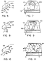
- Figs. 6 and 7 illustrate the air bag 10 14 milliseconds after the inflator module was activated to produce inflation gas.
- the air bag 10 has burst through the panel 36 of dashboard 32 , deployed upwardly along the window 34 and an upper portion 40b of the frontal surface 40 has begun deploying toward the passenger occupant position, at a height substantially above the dashboard 32.
- the upper portion of the bag, in the vicinity of 40b, has also begun lateral expansion to provide a broad frontal surface.
- the bag material is relatively slack, and the exterior surface is somewhat bumpy, as the material is unevenly filled. This is also seen by the dotted line 62 which represents a vertical center line of the front panel material, stitched at 42.
- Figs. 8 and 9 illustrate deployment and inflation of the air bag at 16 milliseconds into the process.
- the frontal surface 40 has expanded downwardly, and is best seen in Fig. 8 , and has also expanded laterally, as best seen in Fig. 9 .
- a trough has begun to form in the central part of the frontal surface, as indicated at 60 , and relatively lumpy filling bubbles of slack material expand outwardly on either side of the trough 60 .
- Fig. 8 there is also shown schematically the believed location of the stitching 42 and, in dotted line 62 , the fabric extending from the stitching along the center line of the bag.
- the bag is still only partially inflated, and contact with a passenger would not be expected at this point.
- the deployment and inflation is shown at 18 milliseconds after triggering of the inflation module.
- the frontal surface 40 continues to expand downwardly, and the center line material 62 becomes more taut.
- the trough 60 begins to open as the frontal surface 40 emerges, and the stitching 42 appears in the trough.
- lateral expansion of the air bag 10 continues, along with the vertical expansion, in contrast to the air bag forming in an outwardly extending column.
- Figs. 12 and 13 illustrate the extent of deployment at 21 milliseconds into the inflation process.
- the frontal surface 40 continues to expand downwardly, and lateral expansion continues as well.
- the center line material shown dotted line 62 is substantially taut, and the trough 60 becomes somewhat deeper as the material on either side of the taut center line material expands to the sides.
- the surfaces are still somewhat lumpy, because although a volume of inflation gas is present, inflation pressure has not built up inside the air bag 10 .
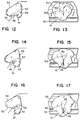
- Figs. 14 and 15 illustrate the air bag at 23 milliseconds after triggering of the inflation module.
- a further elongated frontal surface 40 is forming, and a depending lobe portion of the bag is also becoming more prominent at 52 .
- the center line material 62 has become taut and "jerked" by the outwardly deploying bag, and the stitching 42 is partially broken away.
- the trough 60 has become localized, narrow and deep, indicating the retarding effect on the deployment of the centermost portion of the bag. Nevertheless, the bag has formed substantial lateral and vertical dimensions, again without excessive outward deployment.
- Figs. 16 and 17 illustrate the deployment and inflation of the air bag at 25 milliseconds after triggering.
- the stitches 42 are tearing away, and more of the center line material 62 is free to deploy outwardly and fill in the front surface 40 of the air bag 10 .
- Fig. 17 wherein the upper end of trough 60 is relaxed as the central panel material is released to come forward. The release also contributes to lateral expansion of the air bag 10 .
- contact with a passenger is possible.
- the air bag 10 is deployed with a good lateral and vertical dimension and is sufficiently inflated - with inflation continuing - to provide protection.
- Figs. 18 and 19 illustrate deployment and inflation of the air bag 10 at 27 milliseconds after triggering of the inflation module.
- the stitching 42 is now fully broken away, and the center panel is free to deploy outwardly.
- the upper portion 40a of the frontal surface 40 is enlarged vertically, and the material forming the trough 60 has relaxed and deployed forwardly.
- the depending lobe 52 also extends further downwardly, enlarging the vertical extent of the air bag.
- the dotted line 62 of the central material is shown assuming a more planer frontal surface, in effect catching up with the material on either side thereof.
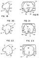
- the deployment and inflation process is shown at 30 milliseconds into the process.
- the air bag 10 has achieved additional volume, pursuant to the time of operation of the gas generator, and the air bag 10 assumes a more planer front surface 40 and an increasingly enlarged depending lobe 52.
- the material in the vicinity of the trough 60 is substantially flattened, and is moving forward.
- the air bag 10 is shown at 33 milliseconds after triggering of the inflation module.
- the front surface 40 has become more vertically elongated, and in particular has deployed outwardly toward the passenger opposite the dashboard 32.
- the trough 60 has substantially smoothed out, and the air bag 10 has assumed a rounded configuration.
- Figs. 24 and 25 illustrate the air bag 10 36 milliseconds after triggering of the inflation module, at which time the air bag is substantially fully inflated.
- the air bag 10 has developed a vertically elongated front surface 40 and a depending lobe which extends well below the center of dashboard 32 and the inflater module mounted therein.
- the depending lobe 52 essentially fills the lap of the passenger so that the passenger's energy is spread over the largest possible surface of the air bag and passenger restraint and cushioning is maximized.
- the material in the vicinity of the stitching 42 has fully deployed to the outermost surface of the air bag 10.
- FIGs. 6-25 illustrate a controlled deployment and shaping of the air bag 10, wherein the air bag 10 does not form a column and extend outwardly beyond the final fully inflated position of Figs. 24 and 25. Instead, the air bag 10 deploys outwardly to a limited extent and then develops a vertically elongated frontal surface and depending lobe as the air bag fills and becomes fully inflated and rounded.
- the rapid downward deployment of the vertical surface is very useful for passenger protection, in that the air bag is better positioned to receive not only the head but the upper torso of the passenger and to receive smaller passengers, including children.
- the formation of the frontal surface rotates downwardly as the stitching limits the deployment of the central panel, thus encouraging the air bag to take its deployed shape and position in front of the passenger early in the inflation process.
- the time delay between the onset of a crash and triggering of the gas generator the response and output of the gas generator, the location and orientation of the inflator module including the folded bag on the dashboard, and the dimensions of the vehicle. Desired operation can nevertheless be achieved by varying the location of the stitches, the stitch pattern, the number of stitches and the strength of the thread used for the stitches.
- the air bag can be constructed of panels of different configurations, without altering the benefits achieved from releasably securing the front panel to the rear panel below the inlet opening.
- an air bag 70 is shown in fragmentary view in Fig. 26, the air bag 70 having a central panel 72 and side panels 74 and 76.
- Stitching 78 and 80 is applied to releasably secure the central panel 72 to itself below the inlet opening in a depending lobe portion of bag 70 .
- Stitches 78 are applied in nested "W" pattern within a circle 82 , the circle 82 constituting fine stitches sewing a circular reinforcement patch under the central panel 72.
- Stitching 80 is applied in a zigzag pattern, also within circular stitching 84 securing a circular reinforcing patch to the back of front panel 72 .
- Air bag 100 comprises a central panel 102 and side panels 104 and 106, connected at seams 105 and 107, and has the general shape, including a depending lobe, of air bag 10.
- a collar portion 108 of the air bag 100 defining its inlet opening includes a folded, stitched hem and openings for attaching the air bag to an inflator module, not shown.
- Stitching generally indicated at 110 releasably secures the front panel 102 to itself, below the inlet opening.
- the stitching is provided in seven vertically elongated converging stitch lines 112, which have their greater spacing at the end portion closer to the inlet opening, indicated at 114 in Fig. 27 .
- the stitches at end 114 of the stitch lines 112 are the first to release during the deployment and inflation process.
- the converging pattern of stitch lines 112 provides both a greater width of stitching at the area of first release and imparts non-parallel force vectors to the air bag material, to resist formation of stress risers that could result in fabric failure.
- stitch density means a greater number of stitches in a given area, whether achieved by application of more stitch lines, utilization of more stitches per unit length, or both.
- stitch lines 112 are approximately ten inches long with 5-7 stitches per inch, and the stitch line segments are approximately one inch long with 8-10 stitches per inch.
- Ninety pound nylon thread is used for the stitches.
- the air bag 100 is reinforced in the area of the breakaway stitches 110.
- a first reinforcing patch is sewn to the inside of the front surface of central panel 102 by stitching 118 and although the patch is not seen, it is outlined by stitching 118.
- a second reinforcing patch 120 is sewn by stitching 122 to the inside of central panel comprising the rear of the depending lobe. Reinforcing patch 120 extends to the collar 108, thus provides a reinforced connection of the area of breakaway stitching with a mounting collar at the inflator module.
- the additional stitch density at the area of stitching which first releases resists premature separation of the releasably secured portions of the air bag, and insures downward rotation of the forming vertically elongated frontal surface before release of the lower frontal surface.
- the air bags 10 , 70 and 100 shown and described herein are but some representations of possible stitch patterns and shapes and deployments of reinforcing patches. Although the invention contemplates locating the releasable stitching on the central panel of an air bag below the inlet opening, i.e., in the depending lobe area, alternate positions within that general vicinity may also be utilized to optimize performance for a given set of parameters.
Landscapes
- Engineering & Computer Science (AREA)
- Mechanical Engineering (AREA)
- Air Bags (AREA)
Applications Claiming Priority (4)
| Application Number | Priority Date | Filing Date | Title |
|---|---|---|---|
| US08/029,690 US5378019A (en) | 1993-03-11 | 1993-03-11 | Controlled deployment driver's side air bag |
| US29690 | 1993-03-11 | ||
| US42122 | 1993-04-02 | ||
| US08/042,122 US5395134A (en) | 1993-04-02 | 1993-04-02 | Passenger side air bag with controlled deployment |
Publications (2)
| Publication Number | Publication Date |
|---|---|
| EP0614785A1 true EP0614785A1 (fr) | 1994-09-14 |
| EP0614785B1 EP0614785B1 (fr) | 1996-11-27 |
Family
ID=26705228
Family Applications (1)
| Application Number | Title | Priority Date | Filing Date |
|---|---|---|---|
| EP19940300795 Expired - Lifetime EP0614785B1 (fr) | 1993-03-11 | 1994-02-03 | Sac gonflable cÔté passager à déploiement contrÔlé |
Country Status (2)
| Country | Link |
|---|---|
| EP (1) | EP0614785B1 (fr) |
| DE (1) | DE69400970T2 (fr) |
Cited By (3)
| Publication number | Priority date | Publication date | Assignee | Title |
|---|---|---|---|---|
| DE19529561C1 (de) * | 1995-08-11 | 1996-10-02 | Audi Ag | Gaskisseneinheit |
| EP0800959A3 (fr) * | 1996-04-08 | 1998-09-16 | Takata Corporation | Dispositif air-bag |
| CN108202689A (zh) * | 2016-12-19 | 2018-06-26 | 现代自动车株式会社 | 用于车辆的前安全气囊 |
Families Citing this family (1)
| Publication number | Priority date | Publication date | Assignee | Title |
|---|---|---|---|---|
| DE10355487B4 (de) * | 2003-11-27 | 2006-11-02 | Trw Occupant Restraint Systems Gmbh & Co. Kg | Gassack für ein Fahrzeuginsassen-Rückhaltesystem |
Citations (5)
| Publication number | Priority date | Publication date | Assignee | Title |
|---|---|---|---|---|
| US3586347A (en) * | 1969-06-05 | 1971-06-22 | Eaton Yale & Towne | Safety device |
| DE2944319A1 (de) * | 1979-11-02 | 1981-05-14 | Daimler-Benz Ag, 7000 Stuttgart | Aufblasbares aufprallschutzkissen |
| EP0344422A2 (fr) * | 1988-05-28 | 1989-12-06 | Daimler-Benz Aktiengesellschaft | Sac d'air pour les occupants d'un véhicule |
| US5022675A (en) * | 1989-11-30 | 1991-06-11 | Allied-Signal Inc. | Air bag and folding technique |
| EP0495409A1 (fr) * | 1991-01-17 | 1992-07-22 | TRW Occupant Restraint Systems GmbH | Coussin d'air gonflable pour un système de retenue dans des véhicules |
-
1994
- 1994-02-03 EP EP19940300795 patent/EP0614785B1/fr not_active Expired - Lifetime
- 1994-02-03 DE DE1994600970 patent/DE69400970T2/de not_active Expired - Fee Related
Patent Citations (5)
| Publication number | Priority date | Publication date | Assignee | Title |
|---|---|---|---|---|
| US3586347A (en) * | 1969-06-05 | 1971-06-22 | Eaton Yale & Towne | Safety device |
| DE2944319A1 (de) * | 1979-11-02 | 1981-05-14 | Daimler-Benz Ag, 7000 Stuttgart | Aufblasbares aufprallschutzkissen |
| EP0344422A2 (fr) * | 1988-05-28 | 1989-12-06 | Daimler-Benz Aktiengesellschaft | Sac d'air pour les occupants d'un véhicule |
| US5022675A (en) * | 1989-11-30 | 1991-06-11 | Allied-Signal Inc. | Air bag and folding technique |
| EP0495409A1 (fr) * | 1991-01-17 | 1992-07-22 | TRW Occupant Restraint Systems GmbH | Coussin d'air gonflable pour un système de retenue dans des véhicules |
Cited By (5)
| Publication number | Priority date | Publication date | Assignee | Title |
|---|---|---|---|---|
| DE19529561C1 (de) * | 1995-08-11 | 1996-10-02 | Audi Ag | Gaskisseneinheit |
| EP0800959A3 (fr) * | 1996-04-08 | 1998-09-16 | Takata Corporation | Dispositif air-bag |
| US5979937A (en) * | 1996-04-08 | 1999-11-09 | Takata Corporation | Air bag device |
| CN108202689A (zh) * | 2016-12-19 | 2018-06-26 | 现代自动车株式会社 | 用于车辆的前安全气囊 |
| CN108202689B (zh) * | 2016-12-19 | 2022-02-18 | 现代自动车株式会社 | 用于车辆的前安全气囊 |
Also Published As
| Publication number | Publication date |
|---|---|
| DE69400970T2 (de) | 1997-04-10 |
| EP0614785B1 (fr) | 1996-11-27 |
| DE69400970D1 (de) | 1997-01-09 |
Similar Documents
| Publication | Publication Date | Title |
|---|---|---|
| US5395134A (en) | Passenger side air bag with controlled deployment | |
| US5378019A (en) | Controlled deployment driver's side air bag | |
| US7942443B2 (en) | Airbag system | |
| US5489119A (en) | Tethers with tearseams for air bag cushion | |
| US8096578B2 (en) | Knee airbag | |
| US5899489A (en) | Inflatable safety restraint for vehicle occupant protection | |
| US6554316B2 (en) | Multi-chamber airbag gas venting system | |
| US7134691B2 (en) | Air bag cushion including break-away tethers | |
| US7213836B2 (en) | Curtain air bag module | |
| US7506892B2 (en) | Cushion shaping sleeve and tether for airbags | |
| USRE43353E1 (en) | Divided airbag system | |
| US8388019B2 (en) | Airbag module | |
| US11679734B2 (en) | Frontal airbag | |
| GB2293355A (en) | A side impact airbag deploying from a flexible pocket, attached to the vehicle at two points | |
| JP2019048633A (ja) | 膨張式シートベルトの折り畳みパターン | |
| JP3321978B2 (ja) | エアバッグ装置 | |
| CN103874607B (zh) | 安全气囊模块 | |
| JP4156121B2 (ja) | エアバッグ装置 | |
| EP1813517A1 (fr) | Système d'airbag pour motocyclette et motocyclette | |
| EP0614785B1 (fr) | Sac gonflable cÔté passager à déploiement contrÔlé | |
| JP2010137779A (ja) | エアバッグ装置 | |
| JPH0930353A (ja) | エアバッグ装置 | |
| JP7762316B2 (ja) | 車両用サイドエアバッグ装置 | |
| JPH07125587A (ja) | エアバッグ | |
| WO1995006574A1 (fr) | Sac gonflable a motif a couture dechirable ameliore |
Legal Events
| Date | Code | Title | Description |
|---|---|---|---|
| PUAI | Public reference made under article 153(3) epc to a published international application that has entered the european phase |
Free format text: ORIGINAL CODE: 0009012 |
|
| AK | Designated contracting states |
Kind code of ref document: A1 Designated state(s): BE DE ES FR GB IT NL SE |
|
| 17P | Request for examination filed |
Effective date: 19941004 |
|
| 17Q | First examination report despatched |
Effective date: 19950731 |
|
| GRAG | Despatch of communication of intention to grant |
Free format text: ORIGINAL CODE: EPIDOS AGRA |
|
| GRAH | Despatch of communication of intention to grant a patent |
Free format text: ORIGINAL CODE: EPIDOS IGRA |
|
| GRAH | Despatch of communication of intention to grant a patent |
Free format text: ORIGINAL CODE: EPIDOS IGRA |
|
| GRAA | (expected) grant |
Free format text: ORIGINAL CODE: 0009210 |
|
| AK | Designated contracting states |
Kind code of ref document: B1 Designated state(s): BE DE ES FR GB IT NL SE |
|
| PG25 | Lapsed in a contracting state [announced via postgrant information from national office to epo] |
Ref country code: NL Free format text: LAPSE BECAUSE OF FAILURE TO SUBMIT A TRANSLATION OF THE DESCRIPTION OR TO PAY THE FEE WITHIN THE PRESCRIBED TIME-LIMIT Effective date: 19961127 Ref country code: ES Free format text: THE PATENT HAS BEEN ANNULLED BY A DECISION OF A NATIONAL AUTHORITY Effective date: 19961127 Ref country code: BE Effective date: 19961127 |
|
| REF | Corresponds to: |
Ref document number: 69400970 Country of ref document: DE Date of ref document: 19970109 |
|
| PGFP | Annual fee paid to national office [announced via postgrant information from national office to epo] |
Ref country code: FR Payment date: 19970219 Year of fee payment: 4 |
|
| ET | Fr: translation filed | ||
| ITF | It: translation for a ep patent filed | ||
| PG25 | Lapsed in a contracting state [announced via postgrant information from national office to epo] |
Ref country code: SE Effective date: 19970227 |
|
| NLV1 | Nl: lapsed or annulled due to failure to fulfill the requirements of art. 29p and 29m of the patents act | ||
| PLBE | No opposition filed within time limit |
Free format text: ORIGINAL CODE: 0009261 |
|
| STAA | Information on the status of an ep patent application or granted ep patent |
Free format text: STATUS: NO OPPOSITION FILED WITHIN TIME LIMIT |
|
| 26N | No opposition filed | ||
| PG25 | Lapsed in a contracting state [announced via postgrant information from national office to epo] |
Ref country code: FR Free format text: THE PATENT HAS BEEN ANNULLED BY A DECISION OF A NATIONAL AUTHORITY Effective date: 19980228 |
|
| REG | Reference to a national code |
Ref country code: FR Ref legal event code: ST |
|
| REG | Reference to a national code |
Ref country code: GB Ref legal event code: IF02 |
|
| PGFP | Annual fee paid to national office [announced via postgrant information from national office to epo] |
Ref country code: GB Payment date: 20040128 Year of fee payment: 11 |
|
| PG25 | Lapsed in a contracting state [announced via postgrant information from national office to epo] |
Ref country code: IT Free format text: LAPSE BECAUSE OF NON-PAYMENT OF DUE FEES;WARNING: LAPSES OF ITALIAN PATENTS WITH EFFECTIVE DATE BEFORE 2007 MAY HAVE OCCURRED AT ANY TIME BEFORE 2007. THE CORRECT EFFECTIVE DATE MAY BE DIFFERENT FROM THE ONE RECORDED. Effective date: 20050203 Ref country code: GB Free format text: LAPSE BECAUSE OF NON-PAYMENT OF DUE FEES Effective date: 20050203 |
|
| GBPC | Gb: european patent ceased through non-payment of renewal fee |
Effective date: 20050203 |
|
| PGFP | Annual fee paid to national office [announced via postgrant information from national office to epo] |
Ref country code: DE Payment date: 20081229 Year of fee payment: 16 |
|
| PG25 | Lapsed in a contracting state [announced via postgrant information from national office to epo] |
Ref country code: DE Free format text: LAPSE BECAUSE OF NON-PAYMENT OF DUE FEES Effective date: 20100901 |