EP0615073A1 - Combinaison d'écran et rondelle - Google Patents
Combinaison d'écran et rondelle Download PDFInfo
- Publication number
- EP0615073A1 EP0615073A1 EP93104042A EP93104042A EP0615073A1 EP 0615073 A1 EP0615073 A1 EP 0615073A1 EP 93104042 A EP93104042 A EP 93104042A EP 93104042 A EP93104042 A EP 93104042A EP 0615073 A1 EP0615073 A1 EP 0615073A1
- Authority
- EP
- European Patent Office
- Prior art keywords
- nut
- perforated disc
- combination
- threaded bolt
- bore
- Prior art date
- Legal status (The legal status is an assumption and is not a legal conclusion. Google has not performed a legal analysis and makes no representation as to the accuracy of the status listed.)
- Granted
Links
Images


Classifications
-
- F—MECHANICAL ENGINEERING; LIGHTING; HEATING; WEAPONS; BLASTING
- F16—ENGINEERING ELEMENTS AND UNITS; GENERAL MEASURES FOR PRODUCING AND MAINTAINING EFFECTIVE FUNCTIONING OF MACHINES OR INSTALLATIONS; THERMAL INSULATION IN GENERAL
- F16B—DEVICES FOR FASTENING OR SECURING CONSTRUCTIONAL ELEMENTS OR MACHINE PARTS TOGETHER, e.g. NAILS, BOLTS, CIRCLIPS, CLAMPS, CLIPS OR WEDGES; JOINTS OR JOINTING
- F16B37/00—Nuts or like thread-engaging members
- F16B37/08—Quickly-detachable or mountable nuts, e.g. consisting of two or more parts; Nuts movable along the bolt after tilting the nut
-
- A—HUMAN NECESSITIES
- A47—FURNITURE; DOMESTIC ARTICLES OR APPLIANCES; COFFEE MILLS; SPICE MILLS; SUCTION CLEANERS IN GENERAL
- A47K—SANITARY EQUIPMENT; ACCESSORIES THEREFOR, e.g. TOILET ACCESSORIES
- A47K13/00—Seats or covers for all kinds of closets
- A47K13/24—Parts or details not covered in, or of interest apart from, groups A47K13/02 - A47K13/22
- A47K13/26—Mounting devices for seats or covers
-
- F—MECHANICAL ENGINEERING; LIGHTING; HEATING; WEAPONS; BLASTING
- F16—ENGINEERING ELEMENTS AND UNITS; GENERAL MEASURES FOR PRODUCING AND MAINTAINING EFFECTIVE FUNCTIONING OF MACHINES OR INSTALLATIONS; THERMAL INSULATION IN GENERAL
- F16B—DEVICES FOR FASTENING OR SECURING CONSTRUCTIONAL ELEMENTS OR MACHINE PARTS TOGETHER, e.g. NAILS, BOLTS, CIRCLIPS, CLAMPS, CLIPS OR WEDGES; JOINTS OR JOINTING
- F16B37/00—Nuts or like thread-engaging members
- F16B37/16—Wing-nuts
-
- F—MECHANICAL ENGINEERING; LIGHTING; HEATING; WEAPONS; BLASTING
- F16—ENGINEERING ELEMENTS AND UNITS; GENERAL MEASURES FOR PRODUCING AND MAINTAINING EFFECTIVE FUNCTIONING OF MACHINES OR INSTALLATIONS; THERMAL INSULATION IN GENERAL
- F16B—DEVICES FOR FASTENING OR SECURING CONSTRUCTIONAL ELEMENTS OR MACHINE PARTS TOGETHER, e.g. NAILS, BOLTS, CIRCLIPS, CLAMPS, CLIPS OR WEDGES; JOINTS OR JOINTING
- F16B43/00—Washers or equivalent devices; Other devices for supporting bolt-heads or nuts
Definitions
- the invention relates to a combination of a nut and perforated disc for clamping a bore in a axially movable threaded bolt which is positively fixed at one end of the bore in the axial direction by a contact surface and emerges from the bore at the other end, said nut a radial, extending to its thread, over the entire height of the nut extending slot has.
- a connecting element consisting of a threaded bolt and a nut, wherein the threaded bolt or the like generally in a bore of parts to be joined together. is movable in the axial direction and by a contact surface, such as a screw head, at one end of the bore is positively fixed and emerges at the other end of the bore from this, wherein on the emerging from the bore threaded parts, the nut is screwed.
- a contact surface such as a screw head
- nuts have become known which have a radially disposed slot which extends to the thread of the nut and extends over the entire height of the nut.
- Such a nut makes it possible to push or screw the screw nut in the radial direction in the immediate vicinity of the fastening hole on the threaded bolt and then tighten it, which considerably shortens the assembly process.
- Such a nut is known, for example, from DE-GM 7146313.
- a perforated disc is not described, but it is well known, to reduce the surface pressure and to compensate for unevenness perforated discs, which are also referred to as washers to use ,
- a disadvantage of the screw nut described in DE-GM 7146313 is that when tightening the nut by the thread flanks forces are generated, which counteract the nut on the proper fit on the threaded bolt, so that the screw when tightening, d. H. a higher tightening torque from which threaded bolt is depressed. Because of this disadvantage, the known from this prior art nut is only suitable for compounds that require a relatively low torque.
- a fastener which consists of a slotted, annular body, wherein an inner wall may carry a thread profile, so that the fastener is used as a nut.
- the fastener or the nut the same problem occurs as in the known from DE-GM 7146313 nut, namely that the high tightening elements can not be realized because the fastener or the nut otherwise of the Threaded bolt is depressed.
- a lock nut which consists of two parts which are rotatably connected to each other by means of a rotationally symmetrical tongue and groove connection and both have a radial slot, so that the entire lock nut then in the radial direction a threaded bolt can be pushed, when the two parts of the lock nut relative to each other so that the two slots come to cover.
- a radial slipping of the threaded bolt is prevented by the fact that the two slots of the two part nuts no longer come together to cover, the entire mother therefore has no continuous radial slot.
- the most common method of tightening the threaded bolt is the use of a wing nut, which must be screwed from below over the entire length of the protruding from the mounting hole part of the threaded bolt until it comes to rest and can be tightened. Since the mounting holes of the toilet bowl due to installation usually run near a wall, due to the height of the toilet bowl near the ground screwing the wing nut on the protruding part of the threaded bolt, due to the limited space, particularly cumbersome and annoying. This implies that the once-mounted toilet seat for reasons of convenience is often removed for cleaning purposes after a first-time installation never again from the usually made of porcelain toilet bowl, which, however, is highly desirable for hygiene reasons.
- a device for fixing a toilet seat in which the projecting through the mounting hole of the toilet bowl threaded bolt is clamped by means of a specially issued mother whose internal thread only to each other is formed diagonally opposite portions, whereby an employed at an angle to the axis of the nut movement bore remains, by means of which a displacement of the nut is made possible by means of the thread of the threaded bolt, without rotation of the nut would be necessary about its axis.
- a disadvantage of this embodiment of a fastening device for a toilet seat it is that the mother is finished earlier and does not allow high torques.
- a fastening device for toilet seats is also known, in which the protruding into the mounting hole of the toilet bowl attachment device is bolt-like, with a surrounding the bolt, substantially annular rubber stopper in a relaxed state an outer diameter which is smaller than the inner diameter of the mounting hole of the toilet bowl, but which can be compressed in the axial direction so that it increases in diameter in the circumferential direction and is wedged in the mounting hole of the toilet bowl.
- This attachment device for a toilet seat has a relatively complicated structure and is not inexpensive to manufacture due to a plurality of components, so that because of the expected high price is given a poor acceptance by the end user.
- a fastening device for a toilet seat in which a spindle as described above with a support plate and a through a mounting hole of the toilet bowl extending threaded bolt forms a fastening device.
- the glasses of the toilet seat and the hinged lid have bearing bores with a radial slot so that they can be pressed onto the fixed journals of the two fasteners.
- the invention is therefore based on the object, a nut with a radial, reaching to its thread, over the entire height of the nut extending slot so that a clamping of a bore axially movable threaded bolt, which at one end of the bore in axial Direction by a contact surface is positively fixed and emerges at the other end of the bore from this, is made possible with high torques, without slipping off at high torques, the nut of the threaded bolt due to the forces occurring approximately radially to the threaded axis.
- the invention is further based on the object to provide a fastening device for a swivel toilet seat, in which a vertically extending from a support plate down through a bore threaded bolt with an inventively to be created nut is tightened quickly and easily with high torques, the Nut and possibly additional elements should be inexpensive to manufacture.
- the object is achieved with regard to its first part by a combination of a split nut and a centering perforated disc, in which the nut has a concentric collar arranged at one end with a center axis inclined to the axis of the nut centering, wherein further to the centering surface to the outside towards a circular contact surface connects, and wherein the inner wall of the hole of the perforated disc extends complementary to the centering inclined.
- both the centering surface of the nut and the wall of the hole are designed as a truncated cone lateral surfaces.
- the perforated disc according to the invention acts by means of its inclined inner wall preferably in the form of a truncated cone lateral surface with the centering of the concentrically arranged collar of the nut together, whereby the screw centered and slipping of the screw is prevented by the bolt due to forces occurring during tightening.
- the inner diameter of the perforated disc is slightly larger than the outer diameter of the threaded bolt, so that the perforated disc can be easily pushed over the protruding from the mounting hole part of the threaded bolt, while the nut in the radial direction immediately below the perforated disc on the Threaded bolt is pressed.
- the inner wall of the hole of the perforated disc consists of two each extending from outside to inside truncated cone lateral surfaces.
- the basic geometric shape of the nut has a straight, the threaded bore receiving circular cylinder, which is followed by a contact surface having circular writing.
- the disc having the contact surface is provided with a radially extending relief slot arranged opposite the slot of the nut.
- This embodiment of the nut according to the invention causes a stable construction and yet is achieved by the relief gap, that the forces necessary for bending the radial slot forces are kept small, so that the Aufsteckvorgang the nut is simplified on the threaded bolt.
- the contact surface having circular disc can be further shortened by a right angle to the slot arranged circular segment, whereby the attachment of the nut is simplified on the threaded bolt and material is saved.
- the nut has two wing-like gripping surfaces, which are preferably arranged in a plane perpendicular to the plane containing the nut screw axis and which may also be connected to the circular cylinder and extend over the entire free height of the same.
- Such an embodiment of the nut according to the invention allows an assembly of the same by hand, without special tools would be required.
- the nut and the perforated disc are made by injection molding of a plastic, wherein the centering surface and the inner wall are inclined in a preferred embodiment at an angle of 30 °.
- the solution of the problem in a generic fastening device for a swivel toilet seat is characterized in that the screwed onto the threaded bolt from below fastener is an above-described inventive combination of nut and orifice plate.
- a fastening device for a pivotable toilet seat beyond that the support plate, which is formed integrally perpendicular to this downwardly extending threaded bolt and the distance from the support plate horizontally arranged axle and made by injection molding of plastic.
- the screw nut and the perforated disc are preferably made by injection molding of plastic, so that a cost-effective fastening device is provided.
- the threaded bolt merges into a non-threaded, angled, the axle journal forming part and that the support plate is screwed onto the threaded bolt, preferably both threaded bolts as support plates made of metal.
- Such a nut 10 has a circular cylindrical body 12 which carries a concentric with its axis A arranged internal thread 14. At a lower end of the thread 14, the nut 10 has a concentric to the axis A of the nut arranged collar 16, which has the geometric shape of a truncated cone. In the radial direction of the federal government is limited by a centering surface 18, which is geometrically a truncated cone lateral surface. The acute angle of the truncated cone is 60 °, ie the truncated cone surface, so the centering surface is inclined at an angle of 30 ° to the axis A of the nut.
- annular contact surface 20, which belongs to a circular disk 22 connected to the cylinder body 12, adjoins the centering surface 18 toward the outside.
- the nut according to the invention has a radial slot 14 extending to its thread 14, which extends over the entire height of the nut, as FIG. 2 shows.
- the slot 24 is chosen in size and shape so that the remaining of the thread 14 circumferential angle is greater than 180 °, ie the cut out of the slot from the circumference of the thread circle segment has an acute angle, which is smaller than 180 ° , for example 160 °.
- the slot also extends through the circular disk 22.
- the side portions 22 a and 22 b of the circular disk 22 and the adjacent areas of the cylindrical main body 12 are pressed, which is additionally facilitated by a relief gap 26.
- the relief gap 26 is disposed opposite the slot 24.
- the nut also has two wing-like gripping surfaces 28a and 28b arranged in a plane, by means of which the screw can be tightened or twisted without the need for a special tool.
- the wings 28a and 28b are disposed in a plane perpendicular to the plane A of the slot 24 containing the axis A of the nut.
- the mutual arrangement of relief gap 26, slot 24 and gripping surfaces 28a and 28b, a good stability of the screw is achieved with good material utilization, so that the screw can be made in particular by injection molding.
- FIGS. 5 and 6 show the perforated disk according to the invention.
- the perforated disc 30 has a concentrically arranged hole 32, whose inner wall 34 consists of two outwardly widening truncated cone lateral surfaces 36a and 36b.
- the angle of inclination of the truncated cone lateral surfaces 36a and 36b with respect to the central axis A is 30 °, as in the embodiment of a screw nut according to the invention shown in FIGS. 1 to 4, while the outer diameter of the truncated cone lateral surfaces is slightly smaller than the largest diameter of the truncated cone lateral surface 18 of the Federal 16.
- the centering surface come in the form of the truncated cone surface 18 with the truncated cone surface 36a of the inner wall 34 of the perforated disc 30 in contact or - in an inverted position of the perforated disc 30 - with the identically shaped truncated cone surface 36b.
- the collar 16 is compressed in the region of the slot 24, when the centering surface, ie the truncated cone surface 18 of the collar 16, the Forward rotation, so when tightening the nut, further into the complementary truncated cone surface 36a, 36b of the perforated disc 30 is moved. As a result, the nut is centered and slipping of the nut from the threaded bolt, not shown in FIGS. 1 to 6 is prevented.
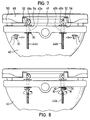
- FIG. 7 shows an application of the inventive combination of nut and perforated disc in the context of a fastening device according to the invention for a pivoting toilet seat.
- a toilet bowl 40 has two mounting holes 42a and 42b, in which axially displaceable threaded bolts 44a and 44b are arranged. In their upper region, the threaded bolts pass into axle stubs 46a and 46b, which run horizontally and engage in bores or through-holes of a pivotable cover 48 and spectacles 50.
- On the thread of the threaded bolts 42a, 42b each designed as Gewinderosette support plate 52 with a contact surface 54 is rotatably arranged.
- the position of the support plate on the respective threaded bolt 44a, 44b can be adjusted, so that the fastening device is universally suitable for any version of toilet seats, d. H. the distance between the stub axles 46a, 46b above the surface 41 of the toilet bowl 40 is adjustable.
- the threaded bolts 44a and 44b are positively fixed by the contact surfaces 54 in the axial direction.
- the length of the threaded bolt 44a and 44b is dimensioned so that the fastening device is universally suitable for toilet bowls with different depth mounting holes 42a and 42b.
- the threaded bolts 44a and 44b are fixed by a combination of a perforated disc 30 and a nut 10 according to the invention.
- FIG. 7 shows schematically, the respective screw nut 10 can be plugged directly below the perforated disc 30 in the radial direction onto the respective threaded bolt 44a, 44b, whereby it is not necessary to cover the entire dead travel of the threaded bolt protruding from the threaded bore by turning the screw nut ,
- the centering surface 18 in the form of a truncated cone surface comes into contact with the downwardly directed portion of the inner wall 34 of the perforated disc 30 when tightening the nut according to the invention, whereby the nut remains centered even when tightening on the respective threaded bolt 44a, 44b and high torques are made possible, so that a tight fit of the toilet seat is ensured on the toilet bowl 40.
Landscapes
- Engineering & Computer Science (AREA)
- General Engineering & Computer Science (AREA)
- Health & Medical Sciences (AREA)
- Public Health (AREA)
- Mechanical Engineering (AREA)
- Dowels (AREA)
- Toilet Supplies (AREA)
- Bolts, Nuts, And Washers (AREA)
- Holders For Apparel And Elements Relating To Apparel (AREA)
- Stringed Musical Instruments (AREA)
- Joining Of Building Structures In Genera (AREA)
- Gripping Jigs, Holding Jigs, And Positioning Jigs (AREA)
- Medicines Containing Plant Substances (AREA)
Priority Applications (8)
| Application Number | Priority Date | Filing Date | Title |
|---|---|---|---|
| DE59301168T DE59301168D1 (de) | 1993-03-12 | 1993-03-12 | Kombination aus Schraubenmutter und Lochscheibe |
| EP93104042A EP0615073B1 (fr) | 1993-03-12 | 1993-03-12 | Combinaison d'écran et rondelle |
| DK93104042.2T DK0615073T3 (da) | 1993-03-12 | 1993-03-12 | Kombination af møtrik og spændeskive |
| ES93104042T ES2083212T3 (es) | 1993-03-12 | 1993-03-12 | Conjunto de tuerca y arandela. |
| AT93104042T ATE131582T1 (de) | 1993-03-12 | 1993-03-12 | Kombination aus schraubenmutter und lochscheibe |
| NO940833A NO180092C (no) | 1993-03-12 | 1994-03-09 | Kombinasjon av skruemutter og hullskive og befestigelsesanordning for et svingbart toalettsete |
| FI941183A FI941183A7 (fi) | 1993-03-12 | 1994-03-11 | Mutterin ja reikälaatan yhdistelmä |
| GR950403320T GR3018408T3 (en) | 1993-03-12 | 1995-12-14 | Nut and washer combination. |
Applications Claiming Priority (1)
| Application Number | Priority Date | Filing Date | Title |
|---|---|---|---|
| EP93104042A EP0615073B1 (fr) | 1993-03-12 | 1993-03-12 | Combinaison d'écran et rondelle |
Publications (2)
| Publication Number | Publication Date |
|---|---|
| EP0615073A1 true EP0615073A1 (fr) | 1994-09-14 |
| EP0615073B1 EP0615073B1 (fr) | 1995-12-13 |
Family
ID=8212691
Family Applications (1)
| Application Number | Title | Priority Date | Filing Date |
|---|---|---|---|
| EP93104042A Expired - Lifetime EP0615073B1 (fr) | 1993-03-12 | 1993-03-12 | Combinaison d'écran et rondelle |
Country Status (8)
| Country | Link |
|---|---|
| EP (1) | EP0615073B1 (fr) |
| AT (1) | ATE131582T1 (fr) |
| DE (1) | DE59301168D1 (fr) |
| DK (1) | DK0615073T3 (fr) |
| ES (1) | ES2083212T3 (fr) |
| FI (1) | FI941183A7 (fr) |
| GR (1) | GR3018408T3 (fr) |
| NO (1) | NO180092C (fr) |
Cited By (5)
| Publication number | Priority date | Publication date | Assignee | Title |
|---|---|---|---|---|
| WO1997021933A1 (fr) * | 1995-12-11 | 1997-06-19 | Car-O-Liner Ab | Dispositif de reglage a tige filetee |
| DE19548364C2 (de) * | 1995-12-22 | 2000-02-17 | Hamberger Industriewerke Gmbh | Halterung für einen WC-Sitz |
| DE102016005990A1 (de) * | 2016-05-17 | 2017-11-23 | MG Components GmbH & Co. KG | Laufrad für Zweiräder mit Unterlegscheibe für Speichennippel |
| FR3054863A1 (fr) * | 2016-08-03 | 2018-02-09 | Airbus Operations Sas | Dispositif d’assemblage comprenant une bague de centrage |
| US11879493B2 (en) | 2019-05-29 | 2024-01-23 | Gordian Enterprises Inc. | Split nut |
Families Citing this family (1)
| Publication number | Priority date | Publication date | Assignee | Title |
|---|---|---|---|---|
| DE102005040663B3 (de) * | 2005-08-26 | 2007-06-06 | Siemens Ag | Formteil zur Erhöhung einer Montagetoleranz |
Citations (8)
| Publication number | Priority date | Publication date | Assignee | Title |
|---|---|---|---|---|
| US1429513A (en) * | 1921-10-15 | 1922-09-19 | B R E Mfg Company | Hinge |
| GB744016A (en) * | 1953-07-13 | 1956-01-25 | Gerald Robert Hermann More | Quick-acting nut |
| FR1420955A (fr) * | 1964-01-16 | 1965-12-10 | Ft Products Ltd | Attache en deux parties formant écrou à montage rapide |
| US3471874A (en) * | 1967-12-22 | 1969-10-14 | American Standard Inc | Easily removed toilet seat |
| US3675530A (en) * | 1970-03-17 | 1972-07-11 | Michel N Victor | Quick release nut |
| US4083288A (en) * | 1976-06-11 | 1978-04-11 | Patrick Yelverton Williams | Split nuts |
| DE2723058A1 (de) * | 1977-05-21 | 1978-11-30 | Hanswerner Jaeger | Befestigungselement |
| FR2613789A1 (fr) * | 1987-04-10 | 1988-10-14 | Peugeot | Ecrou a engagement rapide |
-
1993
- 1993-03-12 DK DK93104042.2T patent/DK0615073T3/da active
- 1993-03-12 EP EP93104042A patent/EP0615073B1/fr not_active Expired - Lifetime
- 1993-03-12 AT AT93104042T patent/ATE131582T1/de active
- 1993-03-12 DE DE59301168T patent/DE59301168D1/de not_active Expired - Lifetime
- 1993-03-12 ES ES93104042T patent/ES2083212T3/es not_active Expired - Lifetime
-
1994
- 1994-03-09 NO NO940833A patent/NO180092C/no not_active IP Right Cessation
- 1994-03-11 FI FI941183A patent/FI941183A7/fi unknown
-
1995
- 1995-12-14 GR GR950403320T patent/GR3018408T3/el unknown
Patent Citations (8)
| Publication number | Priority date | Publication date | Assignee | Title |
|---|---|---|---|---|
| US1429513A (en) * | 1921-10-15 | 1922-09-19 | B R E Mfg Company | Hinge |
| GB744016A (en) * | 1953-07-13 | 1956-01-25 | Gerald Robert Hermann More | Quick-acting nut |
| FR1420955A (fr) * | 1964-01-16 | 1965-12-10 | Ft Products Ltd | Attache en deux parties formant écrou à montage rapide |
| US3471874A (en) * | 1967-12-22 | 1969-10-14 | American Standard Inc | Easily removed toilet seat |
| US3675530A (en) * | 1970-03-17 | 1972-07-11 | Michel N Victor | Quick release nut |
| US4083288A (en) * | 1976-06-11 | 1978-04-11 | Patrick Yelverton Williams | Split nuts |
| DE2723058A1 (de) * | 1977-05-21 | 1978-11-30 | Hanswerner Jaeger | Befestigungselement |
| FR2613789A1 (fr) * | 1987-04-10 | 1988-10-14 | Peugeot | Ecrou a engagement rapide |
Cited By (6)
| Publication number | Priority date | Publication date | Assignee | Title |
|---|---|---|---|---|
| WO1997021933A1 (fr) * | 1995-12-11 | 1997-06-19 | Car-O-Liner Ab | Dispositif de reglage a tige filetee |
| DE19548364C2 (de) * | 1995-12-22 | 2000-02-17 | Hamberger Industriewerke Gmbh | Halterung für einen WC-Sitz |
| DE102016005990A1 (de) * | 2016-05-17 | 2017-11-23 | MG Components GmbH & Co. KG | Laufrad für Zweiräder mit Unterlegscheibe für Speichennippel |
| DE102016005990B4 (de) * | 2016-05-17 | 2025-02-20 | MG Components GmbH & Co. KG | Laufrad für Zweiräder mit Unterlegscheibe für Speichennippel |
| FR3054863A1 (fr) * | 2016-08-03 | 2018-02-09 | Airbus Operations Sas | Dispositif d’assemblage comprenant une bague de centrage |
| US11879493B2 (en) | 2019-05-29 | 2024-01-23 | Gordian Enterprises Inc. | Split nut |
Also Published As
| Publication number | Publication date |
|---|---|
| EP0615073B1 (fr) | 1995-12-13 |
| NO180092B (no) | 1996-11-04 |
| GR3018408T3 (en) | 1996-03-31 |
| NO940833L (no) | 1994-09-13 |
| FI941183A7 (fi) | 1994-09-13 |
| ES2083212T3 (es) | 1996-04-01 |
| NO940833D0 (no) | 1994-03-09 |
| DE59301168D1 (de) | 1996-01-25 |
| ATE131582T1 (de) | 1995-12-15 |
| NO180092C (no) | 1997-02-12 |
| FI941183A0 (fi) | 1994-03-11 |
| DK0615073T3 (da) | 1996-01-29 |
Similar Documents
| Publication | Publication Date | Title |
|---|---|---|
| EP1259738B1 (fr) | Dispositif de connexion de profiles | |
| CH670063A5 (fr) | ||
| DE8910604U1 (de) | Spindelmutteranordnung | |
| EP1930533A1 (fr) | Charnière de porte de véhicule automobile | |
| DE69607462T2 (de) | Selbstsichernde Mutter | |
| DE3027947C2 (de) | Anordnung zur Befestigung eines ersten Teils an einem zweiten Teil mittels eines Bolzens | |
| DE4138144C2 (de) | Einstellbare, planeben montierbare Befestigungseinrichtung | |
| EP0615073A1 (fr) | Combinaison d'écran et rondelle | |
| DE19906480A1 (de) | Hülsenmutter | |
| EP1291535B1 (fr) | Ecrou de blocage et procédé de fabrication | |
| EP2044341B1 (fr) | Écrou de blocage | |
| AT407285B (de) | Kunststoff-befestigungszapfen, insbesondere für möbelbeschläge | |
| DE19915718C2 (de) | Türscharnier für Kraftfahrzeuge | |
| DE102019206750B4 (de) | Vorrichtung zum Ausgleichen von Toleranzen zwischen einem ersten Bauteil und einem zweiten Bauteil | |
| EP1245741A2 (fr) | Robinetterie sanitaire | |
| EP0225622B1 (fr) | Dispositif pour bloquer des boulons contre la rotation | |
| DE2811108A1 (de) | Sperrzahnscheibe | |
| DE69614840T2 (de) | Lösbare nabe für die montage eines drehenden teils auf einer antriebswelle und mit einer lösbaren nabe dieser art versehendes drehendes teil | |
| DE4231339C2 (de) | Vorrichtung zum Paßzentrieren und Paßverbinden von Teilen | |
| DE10245235B4 (de) | Spannsatz | |
| EP3805581B1 (fr) | Système de sécurité de manipulation destiné à la sécurité permanente des écrous | |
| DE102012112362C5 (de) | Ventil mit einer Befestigungseinrichtung | |
| EP1245742A2 (fr) | Robinetterie sanitaire | |
| DE29704055U1 (de) | Aushängbares Türscharnier | |
| DE20218799U1 (de) | Radschraube |
Legal Events
| Date | Code | Title | Description |
|---|---|---|---|
| PUAI | Public reference made under article 153(3) epc to a published international application that has entered the european phase |
Free format text: ORIGINAL CODE: 0009012 |
|
| 17P | Request for examination filed |
Effective date: 19931015 |
|
| AK | Designated contracting states |
Kind code of ref document: A1 Designated state(s): AT BE CH DE DK ES FR GB GR IE IT LI LU MC NL PT SE |
|
| GRAA | (expected) grant |
Free format text: ORIGINAL CODE: 0009210 |
|
| AK | Designated contracting states |
Kind code of ref document: B1 Designated state(s): AT BE CH DE DK ES FR GB GR IE IT LI LU MC NL PT SE |
|
| REF | Corresponds to: |
Ref document number: 131582 Country of ref document: AT Date of ref document: 19951215 Kind code of ref document: T |
|
| REG | Reference to a national code |
Ref country code: IE Ref legal event code: FG4D Free format text: 66556 |
|
| GBT | Gb: translation of ep patent filed (gb section 77(6)(a)/1977) |
Effective date: 19951214 |
|
| REF | Corresponds to: |
Ref document number: 59301168 Country of ref document: DE Date of ref document: 19960125 |
|
| REG | Reference to a national code |
Ref country code: DK Ref legal event code: T3 |
|
| ITF | It: translation for a ep patent filed | ||
| REG | Reference to a national code |
Ref country code: CH Ref legal event code: NV Representative=s name: E. BLUM & CO. PATENTANWAELTE Ref country code: GR Ref legal event code: FG4A Free format text: 3018408 |
|
| ET | Fr: translation filed | ||
| SC4A | Pt: translation is available |
Free format text: 951213 AVAILABILITY OF NATIONAL TRANSLATION |
|
| REG | Reference to a national code |
Ref country code: ES Ref legal event code: FG2A Ref document number: 2083212 Country of ref document: ES Kind code of ref document: T3 |
|
| PLBE | No opposition filed within time limit |
Free format text: ORIGINAL CODE: 0009261 |
|
| 26N | No opposition filed | ||
| PGFP | Annual fee paid to national office [announced via postgrant information from national office to epo] |
Ref country code: GB Payment date: 20010220 Year of fee payment: 9 |
|
| PGFP | Annual fee paid to national office [announced via postgrant information from national office to epo] |
Ref country code: MC Payment date: 20010323 Year of fee payment: 9 |
|
| PGFP | Annual fee paid to national office [announced via postgrant information from national office to epo] |
Ref country code: ES Payment date: 20010326 Year of fee payment: 9 Ref country code: NL Payment date: 20010326 Year of fee payment: 9 |
|
| PGFP | Annual fee paid to national office [announced via postgrant information from national office to epo] |
Ref country code: IE Payment date: 20010329 Year of fee payment: 9 Ref country code: GR Payment date: 20010329 Year of fee payment: 9 |
|
| REG | Reference to a national code |
Ref country code: GB Ref legal event code: IF02 |
|
| PG25 | Lapsed in a contracting state [announced via postgrant information from national office to epo] |
Ref country code: MC Free format text: LAPSE BECAUSE OF NON-PAYMENT OF DUE FEES Effective date: 20020312 Ref country code: IE Free format text: LAPSE BECAUSE OF NON-PAYMENT OF DUE FEES Effective date: 20020312 Ref country code: GB Free format text: LAPSE BECAUSE OF NON-PAYMENT OF DUE FEES Effective date: 20020312 |
|
| PG25 | Lapsed in a contracting state [announced via postgrant information from national office to epo] |
Ref country code: ES Free format text: LAPSE BECAUSE OF NON-PAYMENT OF DUE FEES Effective date: 20020313 |
|
| PG25 | Lapsed in a contracting state [announced via postgrant information from national office to epo] |
Ref country code: NL Free format text: LAPSE BECAUSE OF NON-PAYMENT OF DUE FEES Effective date: 20021001 |
|
| PG25 | Lapsed in a contracting state [announced via postgrant information from national office to epo] |
Ref country code: GR Free format text: LAPSE BECAUSE OF NON-PAYMENT OF DUE FEES Effective date: 20021007 |
|
| GBPC | Gb: european patent ceased through non-payment of renewal fee |
Effective date: 20020312 |
|
| NLV4 | Nl: lapsed or anulled due to non-payment of the annual fee |
Effective date: 20021001 |
|
| REG | Reference to a national code |
Ref country code: IE Ref legal event code: MM4A |
|
| REG | Reference to a national code |
Ref country code: ES Ref legal event code: FD2A Effective date: 20030410 |
|
| PG25 | Lapsed in a contracting state [announced via postgrant information from national office to epo] |
Ref country code: IT Free format text: LAPSE BECAUSE OF NON-PAYMENT OF DUE FEES;WARNING: LAPSES OF ITALIAN PATENTS WITH EFFECTIVE DATE BEFORE 2007 MAY HAVE OCCURRED AT ANY TIME BEFORE 2007. THE CORRECT EFFECTIVE DATE MAY BE DIFFERENT FROM THE ONE RECORDED. Effective date: 20050312 |
|
| REG | Reference to a national code |
Ref country code: CH Ref legal event code: PFA Owner name: ABU-PLAST KUNSTSTOFFBETRIEBE GMBH Free format text: ABU-PLAST KUNSTSTOFFBETRIEBE GMBH#AM BAHNHOF 20#D-96472 ROEDENTAL (DE) -TRANSFER TO- ABU-PLAST KUNSTSTOFFBETRIEBE GMBH#AM BAHNHOF 20#D-96472 ROEDENTAL (DE) |
|
| PGFP | Annual fee paid to national office [announced via postgrant information from national office to epo] |
Ref country code: DK Payment date: 20110328 Year of fee payment: 19 |
|
| PGFP | Annual fee paid to national office [announced via postgrant information from national office to epo] |
Ref country code: AT Payment date: 20110323 Year of fee payment: 19 Ref country code: CH Payment date: 20110328 Year of fee payment: 19 Ref country code: SE Payment date: 20110325 Year of fee payment: 19 Ref country code: PT Payment date: 20110311 Year of fee payment: 19 Ref country code: FR Payment date: 20110401 Year of fee payment: 19 Ref country code: LU Payment date: 20110325 Year of fee payment: 19 |
|
| PGFP | Annual fee paid to national office [announced via postgrant information from national office to epo] |
Ref country code: DE Payment date: 20110331 Year of fee payment: 19 Ref country code: BE Payment date: 20110328 Year of fee payment: 19 |
|
| REG | Reference to a national code |
Ref country code: PT Ref legal event code: MM4A Free format text: LAPSE DUE TO NON-PAYMENT OF FEES Effective date: 20120912 |
|
| BERE | Be: lapsed |
Owner name: *ABU-PLAST KUNSTSTOFFBETRIEBE G.M.B.H. Effective date: 20120331 |
|
| REG | Reference to a national code |
Ref country code: SE Ref legal event code: EUG |
|
| PG25 | Lapsed in a contracting state [announced via postgrant information from national office to epo] |
Ref country code: SE Free format text: LAPSE BECAUSE OF NON-PAYMENT OF DUE FEES Effective date: 20120313 |
|
| REG | Reference to a national code |
Ref country code: CH Ref legal event code: PL |
|
| REG | Reference to a national code |
Ref country code: DK Ref legal event code: EBP |
|
| PG25 | Lapsed in a contracting state [announced via postgrant information from national office to epo] |
Ref country code: PT Free format text: LAPSE BECAUSE OF NON-PAYMENT OF DUE FEES Effective date: 20120912 |
|
| REG | Reference to a national code |
Ref country code: AT Ref legal event code: MM01 Ref document number: 131582 Country of ref document: AT Kind code of ref document: T Effective date: 20120312 |
|
| REG | Reference to a national code |
Ref country code: FR Ref legal event code: ST Effective date: 20121130 |
|
| PG25 | Lapsed in a contracting state [announced via postgrant information from national office to epo] |
Ref country code: FR Free format text: LAPSE BECAUSE OF NON-PAYMENT OF DUE FEES Effective date: 20120402 Ref country code: CH Free format text: LAPSE BECAUSE OF NON-PAYMENT OF DUE FEES Effective date: 20120331 Ref country code: LI Free format text: LAPSE BECAUSE OF NON-PAYMENT OF DUE FEES Effective date: 20120331 Ref country code: BE Free format text: LAPSE BECAUSE OF NON-PAYMENT OF DUE FEES Effective date: 20120331 Ref country code: AT Free format text: LAPSE BECAUSE OF NON-PAYMENT OF DUE FEES Effective date: 20120312 |
|
| REG | Reference to a national code |
Ref country code: DE Ref legal event code: R119 Ref document number: 59301168 Country of ref document: DE Effective date: 20121002 |
|
| REG | Reference to a national code |
Ref country code: PT Ref legal event code: MM4A Free format text: MAXIMUM VALIDITY LIMIT REACHED Effective date: 20130312 |
|
| PG25 | Lapsed in a contracting state [announced via postgrant information from national office to epo] |
Ref country code: DK Free format text: LAPSE BECAUSE OF NON-PAYMENT OF DUE FEES Effective date: 20120331 |
|
| PG25 | Lapsed in a contracting state [announced via postgrant information from national office to epo] |
Ref country code: PT Free format text: LAPSE BECAUSE OF EXPIRATION OF PROTECTION Effective date: 20130320 |
|
| PG25 | Lapsed in a contracting state [announced via postgrant information from national office to epo] |
Ref country code: LU Free format text: LAPSE BECAUSE OF NON-PAYMENT OF DUE FEES Effective date: 20120312 |
|
| PG25 | Lapsed in a contracting state [announced via postgrant information from national office to epo] |
Ref country code: DE Free format text: LAPSE BECAUSE OF NON-PAYMENT OF DUE FEES Effective date: 20121002 |
|
| PG25 | Lapsed in a contracting state [announced via postgrant information from national office to epo] |
Ref country code: PT Free format text: LAPSE BECAUSE OF EXPIRATION OF PROTECTION Effective date: 20120312 |