EP1245741A2 - Robinetterie sanitaire - Google Patents
Robinetterie sanitaire Download PDFInfo
- Publication number
- EP1245741A2 EP1245741A2 EP02002211A EP02002211A EP1245741A2 EP 1245741 A2 EP1245741 A2 EP 1245741A2 EP 02002211 A EP02002211 A EP 02002211A EP 02002211 A EP02002211 A EP 02002211A EP 1245741 A2 EP1245741 A2 EP 1245741A2
- Authority
- EP
- European Patent Office
- Prior art keywords
- fastening
- fastening body
- apron
- external thread
- segments
- Prior art date
- Legal status (The legal status is an assumption and is not a legal conclusion. Google has not performed a legal analysis and makes no representation as to the accuracy of the status listed.)
- Granted
Links
Images


Classifications
-
- E—FIXED CONSTRUCTIONS
- E03—WATER SUPPLY; SEWERAGE
- E03C—DOMESTIC PLUMBING INSTALLATIONS FOR FRESH WATER OR WASTE WATER; SINKS
- E03C1/00—Domestic plumbing installations for fresh water or waste water; Sinks
- E03C1/02—Plumbing installations for fresh water
- E03C1/04—Water-basin installations specially adapted to wash-basins or baths
- E03C1/0401—Fixing a tap to the sanitary appliance or to an associated mounting surface, e.g. a countertop
-
- E—FIXED CONSTRUCTIONS
- E03—WATER SUPPLY; SEWERAGE
- E03C—DOMESTIC PLUMBING INSTALLATIONS FOR FRESH WATER OR WASTE WATER; SINKS
- E03C1/00—Domestic plumbing installations for fresh water or waste water; Sinks
- E03C1/02—Plumbing installations for fresh water
- E03C1/04—Water-basin installations specially adapted to wash-basins or baths
- E03C2001/0416—Water-basin installations specially adapted to wash-basins or baths using a socket for mounting of faucet
-
- Y—GENERAL TAGGING OF NEW TECHNOLOGICAL DEVELOPMENTS; GENERAL TAGGING OF CROSS-SECTIONAL TECHNOLOGIES SPANNING OVER SEVERAL SECTIONS OF THE IPC; TECHNICAL SUBJECTS COVERED BY FORMER USPC CROSS-REFERENCE ART COLLECTIONS [XRACs] AND DIGESTS
- Y10—TECHNICAL SUBJECTS COVERED BY FORMER USPC
- Y10T—TECHNICAL SUBJECTS COVERED BY FORMER US CLASSIFICATION
- Y10T137/00—Fluid handling
- Y10T137/9464—Faucets and spouts
Definitions
- the object of the present invention is a sanitary To design the outlet fitting of the type mentioned at the beginning, that the locking device is easier, in particular from above, is accessible, and the game between Upper part and lower part of the fastening body in their Locking position completely eliminated.
- the locking device according to the invention is thus no longer by a grub screw but by which have a certain elasticity in the radial direction Segments in the lower apron area of the upper part of the mounting body formed with the cam-like the mother interact on the external thread the apron can be turned.
- This has the double advantage that operation from above is possible without any problems, since the mother easily with an appropriate tool is achievable.
- the apron of the Upper part evenly from all sides against that Lower part laid out, so that actually in all directions the play between the upper part and lower part of the fastening body removed with the mother dressed. This stands in contrast to the prior art, where with tightened Grub screw the play between these parts only in the direction of movement of the grub screw can.
- the cam effect is caused by the fact that the Apron of the top part in the area of the slits a conical surface extended downwards and that the inner Shell surface of the mother over at its lower end a complementary conical surface extended downwards.
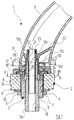
- Figure 1 shows a tub spout, the total with is identified by the reference number 1 and on one Mounting plate 2, e.g. on a support frame for a tub rim installation, is attached.
- the tub spout 1 includes a fastening device 3 in a through hole 4 of the mounting plate 2 in the following Way is mounted, as well as a partially shown Outlet housing 5, which also continues in releasably described below on the fastening device 3 is attached.
- the fastening device 3 has an insertion piece 6, through the through hole 4 of the mounting plate 2 is passed from above and on it outer circumferential surface carries an external thread 7.
- the end of the plug 6 is a radially projecting Flange 7 formed, the interposition of a O-ring seal not shown on the top the mounting plate 2 is present.
- Mother 9 lies down when tightening with interposition of washers 10, 11 against the bottom the mounting plate 2, whereby the plug-in socket 6 is fixed.
- the upper part 12b of the fastening body 12 has a downwardly extending apron 12d and one neck 12e extending upwards.
- the apron 12d has an inner recess 13
- the cross-sectional shape the cross-sectional shape of the neck 12c of the lower part 12a corresponds so that the neck 12c of the lower part 12a is rotationally received in the recess 13.
- the outer contour of the upper region of the apron 12d of the The upper part 12b of the fastening body 12 has the cross-sectional shape a square with rounded corners, like can also be seen in Figures 2 and 3. At the the lower end expands the outside diameter of the Apron 12d over a conical surface 14 (see FIG. 4) a larger radius. In this lowest area the apron 12d also by axially parallel Slots 15 (see Figures 1 and 3) in individual segments 16 divided.
- an external thread 17 incised onto which a nut 18 is screwed on is on the inner surface of one after below apron 19 of the mother 18 also a Tapered surface 20 formed so that the radius of the Inner surface area extended downwards.
- the conical surface 20 is the mother 18 on the approximately complementary inclined Tapered surface 14 of the apron 12d of the fastening upper part 12b.
- An adjustment sleeve 21 is in the through hole from above of the neck 12e of the fastening upper part 12b introduced and axially on this by a snap ring 22 fixed, but with a relative rotation between the adjusting sleeve 21 and the fastening upper part 12b is possible.
- the snap ring 22 is in grooves the mutually facing surfaces of the adjusting sleeve 21 and the fastening upper part 12b snapped.
- At the upper end of the adjusting sleeve 21 are two short, axial extending slots 23 formed on which a workpiece can start to twist the adjusting sleeve 21.
- the adjusting sleeve 21 extends with an external thread 24 load-bearing area in the through hole of the fastening lower part 12a and cooperates an internal thread 25 cut there.
- the area of the Adjustment sleeve 21 has a smooth, cylindrical outer surface on that on the lateral surface of the through hole 26 of the lower fastening part 12a abuts.
- the outlet housing 5 has near its lower end a first transverse wall 27, which is from a through opening 28 is enforced, which is also the cross-sectional shape of a square with rounded corners.
- the apron 12d of the fastening upper part 12b is passed through the through opening 28 of the transverse wall 27; the flat surfaces of the apron 12d lie there almost on the flat surfaces of the passage opening 28 without play.
- a grub screw 30 screwed in a substantially radial through the transverse wall 27 guided threaded bore 29.
- the outer profile of the apron 12d of the fastening upper part 12b is opposite the threaded hole 29 so oriented that the grub screw 30 is not on a flat surface but on the rounded connecting surface between two flat surfaces of the apron 12d hits.
- the neck 12e of the upper fastening part 12b penetrates a complementarily shaped through opening 31 in a second transverse wall 32 of the outlet housing 5 and is run by this.
- the underside of the outlet housing 5 lies on the top a cover rosette 33, which in turn on the top of the mounting plate 2 rests and the flange 8 of the plug 6 partially covered.
- a cylindrical, molded onto the underside of the outlet housing 5 Guide collar 34 extends into the Inner recess of the cover rosette 33 and is managed in this way.
- the plug-in connector 6 and the lower fastening part 12a existing unit on the mounting plate 2 appropriate. This happens because the plug-in connector 6 from above through the opening 4 of the mounting plate 2 is passed, after which the mother 9 from below against the washers 10, 11 and so indirectly against the underside of the mounting plate 2 is tightened.
- the mounting top 12b that is together forms a unit with the adjusting sleeve 21, on the Fastening lower part 12a attached.
- the lower region of the adjusting sleeve 21 in the through hole 26 of the fastening lower part 12a introduced. This can initially be done by pushing; once that External thread 24 of the adjusting sleeve 21, however, with the Internal thread 25 of the lower fastening part 12a engages, the further movement of the adjusting sleeve 21 and the upper fastening part 12b by screwing the adjustment sleeve 21 causes.
- the apron 12d of the fastening upper part 12b now slides over the neck 12c in a rotationally locking manner of the lower fastening part 12a.
- the outlet housing 5 attached to the fastening device 3.
- the neck 12e of the fastening upper part 12b in the complementary through hole 31 of the second Transverse wall 32 and the apron 12d of the fastening upper part 12b in the corresponding receiving opening 28 of the first transverse wall 27 introduced.
- the apron 12d is fastened by the grub screw 30 in a way "in the corner" of the opening 28 pressed, creating a kind of jamming and pass-free Fixation in two directions results from the Fixation by means of the grub screw 30 in a third Direction is added. In this way the outlet housing 5 completely free of play on the fastening upper part 12b attached.
Landscapes
- Health & Medical Sciences (AREA)
- Life Sciences & Earth Sciences (AREA)
- Engineering & Computer Science (AREA)
- Hydrology & Water Resources (AREA)
- Public Health (AREA)
- Water Supply & Treatment (AREA)
- Housings, Intake/Discharge, And Installation Of Fluid Heaters (AREA)
- Devices For Dispensing Beverages (AREA)
- Connector Housings Or Holding Contact Members (AREA)
- Apparatus For Making Beverages (AREA)
- Dowels (AREA)
- Closures For Containers (AREA)
- Details Of Spanners, Wrenches, And Screw Drivers And Accessories (AREA)
- Infusion, Injection, And Reservoir Apparatuses (AREA)
- External Artificial Organs (AREA)
- Percussion Or Vibration Massage (AREA)
Applications Claiming Priority (2)
| Application Number | Priority Date | Filing Date | Title |
|---|---|---|---|
| DE10114854 | 2001-03-26 | ||
| DE2001114854 DE10114854C1 (de) | 2001-03-26 | 2001-03-26 | Sanitäre Auslaufarmatur |
Publications (3)
| Publication Number | Publication Date |
|---|---|
| EP1245741A2 true EP1245741A2 (fr) | 2002-10-02 |
| EP1245741A3 EP1245741A3 (fr) | 2004-07-21 |
| EP1245741B1 EP1245741B1 (fr) | 2005-12-28 |
Family
ID=7679114
Family Applications (1)
| Application Number | Title | Priority Date | Filing Date |
|---|---|---|---|
| EP20020002211 Expired - Lifetime EP1245741B1 (fr) | 2001-03-26 | 2002-01-30 | Robinetterie sanitaire |
Country Status (4)
| Country | Link |
|---|---|
| US (1) | US6588031B2 (fr) |
| EP (1) | EP1245741B1 (fr) |
| AT (1) | ATE314533T1 (fr) |
| DE (2) | DE10114854C1 (fr) |
Cited By (4)
| Publication number | Priority date | Publication date | Assignee | Title |
|---|---|---|---|---|
| AT509653B1 (de) * | 2010-04-14 | 2012-04-15 | Fiereder Simone | Vorrichtung zur befestigung einer armatur |
| WO2014070918A1 (fr) * | 2012-10-31 | 2014-05-08 | Zurn Industries, Llc | Robinet modulaire activé par capteur |
| CN105937254A (zh) * | 2015-03-06 | 2016-09-14 | 高仪股份公司 | 暗装洁具配件 |
| USD787643S1 (en) | 2013-10-30 | 2017-05-23 | Zurn Industries, Llc | Plumbing fitting |
Families Citing this family (6)
| Publication number | Priority date | Publication date | Assignee | Title |
|---|---|---|---|---|
| US7124453B2 (en) * | 2004-06-28 | 2006-10-24 | Tzu-Hsin Sun | Connecting device for connecting a shower head assembly to a wall-mount water supplying pipe |
| US7373674B1 (en) | 2004-12-30 | 2008-05-20 | Sioux Chief Mfg. Co., Inc | Tub spout installation system |
| USD719641S1 (en) | 2013-10-30 | 2014-12-16 | Zurn Industries, Llc | Plumbing fitting |
| USD759210S1 (en) | 2013-10-30 | 2016-06-14 | Zurn Industries, Llc | Plumbing fitting |
| CN105155632B (zh) * | 2015-10-10 | 2017-02-01 | 厦门建霖工业有限公司 | 一种快速拆卸更换龙头主体的方法及其龙头结构 |
| CN105862997A (zh) * | 2016-05-30 | 2016-08-17 | 开平凤成卫浴有限公司 | 一种过孔安装装置 |
Family Cites Families (8)
| Publication number | Priority date | Publication date | Assignee | Title |
|---|---|---|---|---|
| US3827728A (en) * | 1972-10-30 | 1974-08-06 | Vetco Offshore Ind Inc | Pipe connectors |
| FR2383385A1 (fr) * | 1977-03-09 | 1978-10-06 | Legris France Sa | Perfectionnement aux raccords rapides pour tuyaux flexibles renforces multicouches pour fluides |
| SE8204648D0 (sv) * | 1982-08-11 | 1982-08-11 | Andrzej Tomasz Iwanicki | Rorkoppling |
| DE4108458C2 (de) * | 1991-03-15 | 1994-12-15 | Hansa Metallwerke Ag | Sanitärarmatur |
| DE10016504A1 (de) * | 1999-06-29 | 2001-01-04 | Kugler Robinetterie Sa | Befestigungsvorrichtung für eine Armatur auf ihrer Unterlage |
| US6378912B1 (en) * | 1999-07-23 | 2002-04-30 | Sioux Chief Manufacturing Co., Inc. | Apparatus and method for connecting shower heads and tub spouts to a stub out |
| US6123106A (en) * | 1999-12-03 | 2000-09-26 | Emhart Inc. | Thrust washer |
| US6301727B1 (en) * | 2000-04-10 | 2001-10-16 | Moen Incorporated | Modular tub spout assembly |
-
2001
- 2001-03-26 DE DE2001114854 patent/DE10114854C1/de not_active Expired - Fee Related
-
2002
- 2002-01-30 EP EP20020002211 patent/EP1245741B1/fr not_active Expired - Lifetime
- 2002-01-30 DE DE50205396T patent/DE50205396D1/de not_active Expired - Lifetime
- 2002-01-30 AT AT02002211T patent/ATE314533T1/de active
- 2002-03-19 US US10/100,775 patent/US6588031B2/en not_active Expired - Fee Related
Cited By (5)
| Publication number | Priority date | Publication date | Assignee | Title |
|---|---|---|---|---|
| AT509653B1 (de) * | 2010-04-14 | 2012-04-15 | Fiereder Simone | Vorrichtung zur befestigung einer armatur |
| WO2014070918A1 (fr) * | 2012-10-31 | 2014-05-08 | Zurn Industries, Llc | Robinet modulaire activé par capteur |
| USD787643S1 (en) | 2013-10-30 | 2017-05-23 | Zurn Industries, Llc | Plumbing fitting |
| CN105937254A (zh) * | 2015-03-06 | 2016-09-14 | 高仪股份公司 | 暗装洁具配件 |
| CN105937254B (zh) * | 2015-03-06 | 2020-01-21 | 高仪股份公司 | 暗装洁具配件 |
Also Published As
| Publication number | Publication date |
|---|---|
| US20020133874A1 (en) | 2002-09-26 |
| ATE314533T1 (de) | 2006-01-15 |
| EP1245741B1 (fr) | 2005-12-28 |
| EP1245741A3 (fr) | 2004-07-21 |
| US6588031B2 (en) | 2003-07-08 |
| DE10114854C1 (de) | 2002-11-28 |
| DE50205396D1 (de) | 2006-02-02 |
Similar Documents
| Publication | Publication Date | Title |
|---|---|---|
| EP2808457A2 (fr) | Dispositif d'écoulement d'eau pour une installation sanitaire, ainsi que douche à l'italienne | |
| DE4201203A1 (de) | Hahnauslauf | |
| EP1318885B1 (fr) | Outil d'enlevement de copeaux | |
| DE4200899C2 (de) | Befestigungsvorrichtung für eine Sanitärarmatur | |
| DE29707890U1 (de) | Vorrichtung zur Befestigung eines Handlaufelements an einem Pfosten, insbesondere zur Herstellung eines Treppengeländers, und Bausatz dafür | |
| DE4430114C2 (de) | Anschlußstück für einen Kunststoffschlauch einer Badezimmer-Handbrause | |
| EP1245741B1 (fr) | Robinetterie sanitaire | |
| EP3839157A1 (fr) | Robinetterie d'évacuation pour une baignoire sanitaire ou un receveur de douche | |
| DE19528901B4 (de) | Höhenverstellbarer Fuß für Küchengeräte oder Möbel | |
| EP1245742B1 (fr) | Robinetterie sanitaire | |
| DE69922947T2 (de) | Wassereinlauf für Badewanne in Form einer Kaskade | |
| DE3507284C1 (de) | Tränkeinrichtung für Kleintiere | |
| DE10033226A1 (de) | Beweglicher Maschinenfuß mit Dichtfunktion | |
| EP0615073B1 (fr) | Combinaison d'écran et rondelle | |
| EP3184704B1 (fr) | Robinetterie sanitaire | |
| DE102009011560A1 (de) | Sanitäre Einhand-Mischbatterie | |
| DE7026952U (de) | Wandstuetze. | |
| EP0702914A1 (fr) | Elément de tiroir d'ameublement pour tiroirs ou similaires | |
| DE3820458C2 (de) | Tränkeinrichtung für Kleintiere | |
| EP2816160A1 (fr) | Robinet mural avec écartement des connections adaptable | |
| DE3144893A1 (de) | Haltevorrichtung fuer eine handbrause | |
| DE10110379C1 (de) | Einrichtung zur Montage einer Ausziehbrause an einer Trägerplatte | |
| DE10344457A1 (de) | Aufhängevorrichtung | |
| CH680107A5 (en) | Lavatory set attachment to lavatory pan - consists of eccentric seat holder part, with support and fastening bar, one end of which is threaded for nut | |
| AT409075B (de) | Höhenverstellbares fusselement |
Legal Events
| Date | Code | Title | Description |
|---|---|---|---|
| PUAI | Public reference made under article 153(3) epc to a published international application that has entered the european phase |
Free format text: ORIGINAL CODE: 0009012 |
|
| AK | Designated contracting states |
Kind code of ref document: A2 Designated state(s): AT BE CH CY DE DK ES FI FR GB GR IE IT LI LU MC NL PT SE TR |
|
| AX | Request for extension of the european patent |
Free format text: AL;LT;LV;MK;RO;SI |
|
| PUAL | Search report despatched |
Free format text: ORIGINAL CODE: 0009013 |
|
| AK | Designated contracting states |
Kind code of ref document: A3 Designated state(s): AT BE CH CY DE DK ES FI FR GB GR IE IT LI LU MC NL PT SE TR |
|
| AX | Request for extension of the european patent |
Extension state: AL LT LV MK RO SI |
|
| 17P | Request for examination filed |
Effective date: 20041216 |
|
| GRAP | Despatch of communication of intention to grant a patent |
Free format text: ORIGINAL CODE: EPIDOSNIGR1 |
|
| AKX | Designation fees paid |
Designated state(s): AT CH DE FR LI |
|
| GRAS | Grant fee paid |
Free format text: ORIGINAL CODE: EPIDOSNIGR3 |
|
| GRAA | (expected) grant |
Free format text: ORIGINAL CODE: 0009210 |
|
| AK | Designated contracting states |
Kind code of ref document: B1 Designated state(s): AT CH DE FR LI |
|
| REG | Reference to a national code |
Ref country code: CH Ref legal event code: EP |
|
| REF | Corresponds to: |
Ref document number: 50205396 Country of ref document: DE Date of ref document: 20060202 Kind code of ref document: P |
|
| REG | Reference to a national code |
Ref country code: CH Ref legal event code: NV Representative=s name: FREI PATENTANWALTSBUERO |
|
| ET | Fr: translation filed | ||
| PLBE | No opposition filed within time limit |
Free format text: ORIGINAL CODE: 0009261 |
|
| STAA | Information on the status of an ep patent application or granted ep patent |
Free format text: STATUS: NO OPPOSITION FILED WITHIN TIME LIMIT |
|
| 26N | No opposition filed |
Effective date: 20060929 |
|
| REG | Reference to a national code |
Ref country code: FR Ref legal event code: PLFP Year of fee payment: 15 |
|
| REG | Reference to a national code |
Ref country code: FR Ref legal event code: PLFP Year of fee payment: 16 |
|
| PGFP | Annual fee paid to national office [announced via postgrant information from national office to epo] |
Ref country code: CH Payment date: 20170119 Year of fee payment: 16 Ref country code: FR Payment date: 20170120 Year of fee payment: 16 |
|
| PGFP | Annual fee paid to national office [announced via postgrant information from national office to epo] |
Ref country code: AT Payment date: 20170123 Year of fee payment: 16 |
|
| PGFP | Annual fee paid to national office [announced via postgrant information from national office to epo] |
Ref country code: DE Payment date: 20180122 Year of fee payment: 17 |
|
| REG | Reference to a national code |
Ref country code: CH Ref legal event code: PL |
|
| REG | Reference to a national code |
Ref country code: AT Ref legal event code: MM01 Ref document number: 314533 Country of ref document: AT Kind code of ref document: T Effective date: 20180130 |
|
| PG25 | Lapsed in a contracting state [announced via postgrant information from national office to epo] |
Ref country code: FR Free format text: LAPSE BECAUSE OF NON-PAYMENT OF DUE FEES Effective date: 20180131 |
|
| REG | Reference to a national code |
Ref country code: FR Ref legal event code: ST Effective date: 20180928 |
|
| PG25 | Lapsed in a contracting state [announced via postgrant information from national office to epo] |
Ref country code: CH Free format text: LAPSE BECAUSE OF NON-PAYMENT OF DUE FEES Effective date: 20180131 Ref country code: LI Free format text: LAPSE BECAUSE OF NON-PAYMENT OF DUE FEES Effective date: 20180131 Ref country code: AT Free format text: LAPSE BECAUSE OF NON-PAYMENT OF DUE FEES Effective date: 20180130 |
|
| REG | Reference to a national code |
Ref country code: DE Ref legal event code: R119 Ref document number: 50205396 Country of ref document: DE |
|
| PG25 | Lapsed in a contracting state [announced via postgrant information from national office to epo] |
Ref country code: DE Free format text: LAPSE BECAUSE OF NON-PAYMENT OF DUE FEES Effective date: 20190801 |