EP0615093B1 - Indikator für Druckluftflaschen - Google Patents
Indikator für Druckluftflaschen Download PDFInfo
- Publication number
- EP0615093B1 EP0615093B1 EP94102633A EP94102633A EP0615093B1 EP 0615093 B1 EP0615093 B1 EP 0615093B1 EP 94102633 A EP94102633 A EP 94102633A EP 94102633 A EP94102633 A EP 94102633A EP 0615093 B1 EP0615093 B1 EP 0615093B1
- Authority
- EP
- European Patent Office
- Prior art keywords
- indicator
- bore
- compressed air
- air cylinder
- cylindrical
- Prior art date
- Legal status (The legal status is an assumption and is not a legal conclusion. Google has not performed a legal analysis and makes no representation as to the accuracy of the status listed.)
- Expired - Lifetime
Links
- 239000002184 metal Substances 0.000 claims description 25
- 239000011888 foil Substances 0.000 claims description 24
- 238000007789 sealing Methods 0.000 claims description 7
- 238000009530 blood pressure measurement Methods 0.000 abstract description 3
- 230000007246 mechanism Effects 0.000 description 7
- 230000009471 action Effects 0.000 description 3
- 230000000903 blocking effect Effects 0.000 description 3
- 239000012528 membrane Substances 0.000 description 3
- 230000002093 peripheral effect Effects 0.000 description 3
- 229910000639 Spring steel Inorganic materials 0.000 description 1
- 230000008901 benefit Effects 0.000 description 1
- 230000008859 change Effects 0.000 description 1
- 230000002427 irreversible effect Effects 0.000 description 1
- 238000004519 manufacturing process Methods 0.000 description 1
- 239000000463 material Substances 0.000 description 1
- 230000000284 resting effect Effects 0.000 description 1
- 230000007704 transition Effects 0.000 description 1
Images

Classifications
-
- F—MECHANICAL ENGINEERING; LIGHTING; HEATING; WEAPONS; BLASTING
- F17—STORING OR DISTRIBUTING GASES OR LIQUIDS
- F17C—VESSELS FOR CONTAINING OR STORING COMPRESSED, LIQUEFIED OR SOLIDIFIED GASES; FIXED-CAPACITY GAS-HOLDERS; FILLING VESSELS WITH, OR DISCHARGING FROM VESSELS, COMPRESSED, LIQUEFIED, OR SOLIDIFIED GASES
- F17C13/00—Details of vessels or of the filling or discharging of vessels
- F17C13/02—Special adaptations of indicating, measuring, or monitoring equipment
- F17C13/025—Special adaptations of indicating, measuring, or monitoring equipment having the pressure as the parameter
-
- A—HUMAN NECESSITIES
- A62—LIFE-SAVING; FIRE-FIGHTING
- A62C—FIRE-FIGHTING
- A62C13/00—Portable extinguishers which are permanently pressurised or pressurised immediately before use
- A62C13/76—Details or accessories
-
- G—PHYSICS
- G01—MEASURING; TESTING
- G01L—MEASURING FORCE, STRESS, TORQUE, WORK, MECHANICAL POWER, MECHANICAL EFFICIENCY, OR FLUID PRESSURE
- G01L1/00—Measuring force or stress, in general
- G01L1/12—Measuring force or stress, in general by measuring variations in the magnetic properties of materials resulting from the application of stress
-
- F—MECHANICAL ENGINEERING; LIGHTING; HEATING; WEAPONS; BLASTING
- F17—STORING OR DISTRIBUTING GASES OR LIQUIDS
- F17C—VESSELS FOR CONTAINING OR STORING COMPRESSED, LIQUEFIED OR SOLIDIFIED GASES; FIXED-CAPACITY GAS-HOLDERS; FILLING VESSELS WITH, OR DISCHARGING FROM VESSELS, COMPRESSED, LIQUEFIED, OR SOLIDIFIED GASES
- F17C2223/00—Handled fluid before transfer, i.e. state of fluid when stored in the vessel or before transfer from the vessel
- F17C2223/01—Handled fluid before transfer, i.e. state of fluid when stored in the vessel or before transfer from the vessel characterised by the phase
- F17C2223/0107—Single phase
- F17C2223/0123—Single phase gaseous, e.g. CNG, GNC
-
- F—MECHANICAL ENGINEERING; LIGHTING; HEATING; WEAPONS; BLASTING
- F17—STORING OR DISTRIBUTING GASES OR LIQUIDS
- F17C—VESSELS FOR CONTAINING OR STORING COMPRESSED, LIQUEFIED OR SOLIDIFIED GASES; FIXED-CAPACITY GAS-HOLDERS; FILLING VESSELS WITH, OR DISCHARGING FROM VESSELS, COMPRESSED, LIQUEFIED, OR SOLIDIFIED GASES
- F17C2250/00—Accessories; Control means; Indicating, measuring or monitoring of parameters
- F17C2250/04—Indicating or measuring of parameters as input values
- F17C2250/0404—Parameters indicated or measured
- F17C2250/043—Pressure
Definitions
- the invention relates to an indicator on a compressed air bottle or the like.
- an indicator on a compressed air bottle or the like To indicate that the pressure in the compressed air bottle falls below a defined pressure, at least a certain part of the wall of the compressed air bottle being designed in such a way that it is flexible so that this part of the wall is at different pressures is subject to certain different deformations, and an indicator element is provided which is connected to the flexible part of the wall of the compressed air bottle in such a way that it assumes different positions depending on the deformation of the flexible part.
- Pressure gauges were therefore provided, which are screwed into the threaded bores of the compressed gas cylinder and which constantly show the prevailing pressure.
- the seals often have a tendency to leak, since, for example, the seal is crushed by excessive torque when the pressure gauge is screwed in.
- the threads of pressure gauges are often and the compressed gas bottle weld together over time, so that refilling or repairing the compressed gas bottle is no longer possible.
- a warning device for displaying a pressure increase in a container is also already known.
- the container shell there has a gas-tight and pressure-tight opening closed by an elastically deformable cover, with a plunger for signal triggering on the cover, which engages with a corresponding mechanism in such a way that a siren, the actuation of which by compressed air by means of a piston, controls the plunger is triggerable.
- a siren the actuation of which by compressed air by means of a piston
- controls the plunger is triggerable.
- a fire extinguisher which has a cylindrical container, the ends of which are dome-shaped.
- a corresponding device is provided which consists of a spring steel disc which is connected to the outer wall of the container in the region of a container opening via a flange.
- the disc is curved and elastic and can change from its convex to a concave position. It is thin enough that it can be pushed back inwards by hand and remains in this position, the concave side pointing outwards when there is no pressure rests inside the container. However, it changes shape outwards as the internal pressure increases. This position is their normal position. When the container is filled and there is a corresponding internal pressure, the pane can no longer be pressed down by normal hand pressure. If the internal pressure is lower than normal, the disc can be pressed inwards, but as soon as you let go, it will return to its normal, outward position due to the internal pressure.
- the display according to the invention is able to display this overpressure. If the internal pressure rises sharply, it is deformed in a dome shape. The deformation is irreversible due to the permanent metal deformation. If there is a large internal pressure, the display shows this condition permanently.
- This fact is an important advantage of the invention in that a container that has been subjected to high pressure must be discarded. If the dome shape is created in this way, the disc assumes its ideal shape with high internal pressure, consequently there is no crack, the thicker material of the container tears beforehand. The device is therefore used to permanently display an overpressure that has occurred, whereby a tearing of the container is also accepted.
- FR-PS 25 55 290 shows a device for displaying the state of charge of a gas supply device.
- a display element is pivotable into a body installed, which has a flexible membrane which can be acted upon by the gas pressure of the gas supply device and which deforms under gas pressure and interacts with the display.
- a nose arranged on the display element is supported on a plate which is connected to the membrane, so that the display element is moved depending on the deformation of the membrane.
- the pressurized wall of the compressed air bottle with such a small wall thickness that it is subject to certain deformations under pressure or without pressure loads that can be used to actuate an indicator or serve to measure pressure.
- the pressure in such compressed air bottles is 60-200 bar, so that the thin-walled parts of the compressed air bottle can be easily deformed in the desired manner.
- the indicator has an indicator element which is connected directly or indirectly to the flexible part of the wall of the compressed air bottle in such a way that it takes up different positions depending on the deformation of the flexible part.
- an indicator for compressed air bottles it is provided to provide a threaded connection for the indicator mechanism on the compressed air bottle, but the opening to the interior of the compressed air bottle is tightly closed with a metal foil which is provided on the upper edge of the thread, so that no connection outwards through this threaded connection and the metal foil forms part of the pressurized wall of the compressed air bottle.
- a screw cap is screwed onto the external thread, inside which the indicator mechanism is located.
- the sealing cap is drilled through above the metal foil, the inside diameter of the through-hole being reduced in two stages from the inside to the outside. In the widest part of the hole there is a cylindrical body that rests on the metal foil.
- Another cylindrical body is fixedly connected to the cylindrical body and has a diameter that corresponds to the part of the through hole with the smallest diameter.
- This second cylindrical body is flush with the cap when the compressed gas bottle is filled.
- a spiral spring is inserted, which is supported on the second stage of the through hole and on the first cylindrical body.
- an indicator plate is glued, which has a larger diameter than the through hole.
- the circular surface of the second cylindrical element is flush with the cap, but in the unfilled state, the pressure of the coil spring and the lack of internal pressure in the compressed air bottle on the first cylindrical element lower the metal foil and thus the second cylindrical element, and the indicator plate tears off because it cannot be drawn into the cap through the edge of the through hole in the cap, so that when it is not there is an indication that the required pressure is not available.
- the indicator for compressed air bottles it is provided to provide a threaded connection for the indicator mechanism on the compressed air bottle, the opening to the interior of the compressed air bottle being firmly closed with a metal foil, which is provided at the upper edge of the opening, so that none There is a connection to the outside via this threaded connection and the metal foil forms part of the pressurized wall of the compressed air bottle.
- a screw cap is screwed onto the external thread of the bottle neck-like opening of the compressed air bottle, inside which the indicator mechanism is located.
- the closure cap has a cover surface, in the center of which is formed a through hole that becomes narrower in two steps from the inside to the outside, a first cylindrical element being held in the wider step of the through hole and resting firmly on the metal foil.
- the remaining part of the metal foil is covered by the cover surface.
- the first cylindrical element carries in the center a second cylindrical element which has a smaller diameter than the narrower part of the through hole in the cover surface, a spiral spring being arranged around the second cylindrical element.
- the side wall of the closure cap is formed so as to project beyond the cover surface, so that a cylindrical interior is formed which is at the top by a top on the peripheral edge of the side wall overlying closure plate is covered.
- the closure plate is firmly connected to the side wall, either screwed or welded to it.
- the cylindrically shaped indicator element is arranged, the outer diameter of which corresponds to the outer diameter of a through hole in the closure plate, so that the indicator element can, at least partially, emerge from the closure plate in the display case.
- the opening in the closure plate is designed to become narrower in two stages, the outer diameter of the indicator element corresponding to the narrower part of the through hole in the closure plate.
- the indicator element is designed as a pot-like hollow body and preferably has four laterally projecting locking elements which are elastically attached to the indicator element and each have a contact section which can be placed on a holding section in the closure plate.
- the locking elements are elastically pivoted in the indicator element.
- the indicator element is hollow cylindrical, and the second cylindrical element can be inserted into the indicator element like a piston. In the position in which the second cylindrical element is located when the pressure bottle is properly filled, it is pushed into the indicator element to such an extent that the blocking elements are blocked.
- FIG. 1 has an opening 51 on the compressed air bottle 50 which is provided with a metal foil 52 which is firmly connected to the peripheral edge 53 of the threaded opening 51.
- a closure cap 55 is screwed onto the thread 54 of the thread opening 51.
- This cap 55 has in the center a two-stage through hole 56 which becomes narrower from the inside to the outside.
- a cylindrical element 58 is supported, which lies on the metal foil 52 on '.
- This cylindrical element 58 has a second cylindrical element 59 in the center, which has the same diameter as the narrowest part of the through-hole 56.
- the compressed air bottle 50 has an opening 51 which is firmly closed with a metal foil 52 which is firmly connected to the rim 53 of the bottle neck-like opening 51 which runs around the top.
- a closure cap 55 is screwed onto the external thread 54 of the bottle-neck-like opening 51.
- the metal foil is arranged so that there is no connection of the pressure chamber to the outside via the opening 51, since the metal foil forms the flexible part of the wall of the compressed air bottle 50.
- the closure cap 55 has a cover surface 65 which overlaps the opening 51 and thus the metal foil 52 and in the center of which a through bore 66 is formed which becomes narrower in two stages from the inside to the outside.
- a first cylindrical element 68 is held, which rests firmly on the metal foil 52.
- the metal foil is completely covered and supported by the first cylindrical element 68 and the cover surface 65.
- the first cylindrical element 68 carries a second cylindrical element 69 in the middle. This second cylindrical element 69 has a smaller diameter than the narrower step 70 of the through hole 66 in the cover surface 65.
- a spiral spring 71 is arranged around the second cylindrical element 69.
- the lateral wall 72 of the closure cap 55 is formed so as to project beyond the cover surface and encloses a cylindrical interior space 73 open at the top.
- a closure plate 74 placed on top of the peripheral edge of the side wall 72, which is firmly connected to the side wall 72 by being screwed to the side wall 72 with a downwardly projecting section 75.
- An indicator element 76 is arranged in the interior 73 and is cylindrical in shape.
- a two-stage narrowing through opening 77 is formed in the closure plate 74, the outside diameter of the indicator element 76 corresponding to the inside diameter of the narrower part 78 of the through opening 77, while the lower second part 79 of the through hole has a larger inside diameter.
- the indicator element 76 is designed as a pot-like hollow body and has four locking elements 80, 81, 82, 83 arranged in the side wall. These are separated from the side wall 74 of the indicator element by incisions running in the longitudinal direction of the indicator element such that they are only connected to the indicator element via a connecting line 85 and are therefore arranged elastically on the latter. Each locking element has an extension at its free end, which carries a contact surface 86 on the outside.
- the transition between the first stage 78 and the second stage 79 of the through hole 77 in the closure plate 74 is designed as an inclined surface 87, which corresponds in its shape to the contact surface 86 of each locking element 80, 81, 82, 83.
- the lower edge 78 of the indicator element 76 is supported on the spiral spring 71, which in turn is supported on the first cylindrical element 68.
- the coil spring 71 therefore presses from below against the indicator element 76, which would pass through the through hole 77 in the closure plate 74 if the contact surfaces 86 of the locking elements 80, 81, 82, 83 were not in contact with the inclined surface 87 in the closure plate 74 and thus that Indicator element 76 would hold back.
- the locking elements 80, 81, 82, 83 are prevented from pivoting inwards and releasing the indicator element 76, since the indicator element 76 is hollow-cylindrical and the second cylindrical element 69 is inserted into the indicator element like a piston.
- the second cylindrical element 69 In the position in which the second cylindrical element 69 is when the compressed air bottle 50 is properly filled, the second cylindrical element 69 is inserted into the indicator element 76 to such an extent that the locking elements 80, 81, 82, 83 are blocked against pivoting inward. These can then not pivot out of their blocking position and with the contact surface 86, the support section formed by the inclined surface 87 in the locking plate 74, so that the indicator element 76 is held firmly in the locking plate 74.
- the second cylindrical element 68 moves out of the indicator element 76 in the direction designated X in the drawing.
- the locking elements 80, 81, 82, 83 can move inward in the Y direction into the interior of the indicator element 76 and the indicator element 76 is no longer held in the closure plate 74.
- the indicator element 76 is pushed through the through opening 77 in the closure plate 74.
- the indicator element either protrudes or it is completely ejected. In any case, it is immediately apparent from the outside that the pressure has fallen below a certain predetermined limit.
Landscapes
- Engineering & Computer Science (AREA)
- Emergency Management (AREA)
- General Physics & Mathematics (AREA)
- Health & Medical Sciences (AREA)
- Public Health (AREA)
- Business, Economics & Management (AREA)
- Mechanical Engineering (AREA)
- Physics & Mathematics (AREA)
- General Engineering & Computer Science (AREA)
- Closures For Containers (AREA)
- Compressor (AREA)
- Air-Conditioning For Vehicles (AREA)
- Cooling, Air Intake And Gas Exhaust, And Fuel Tank Arrangements In Propulsion Units (AREA)
- Filling Or Discharging Of Gas Storage Vessels (AREA)
- Measuring Fluid Pressure (AREA)
Description
- Die Erfindung betrifft einen Indikator an einer Druckluftflasche od. dgl. zur Anzeige des Unterschreitens eines definierten Druckes in der Druckluftflasche, wobei mindestens ein bestimmter Teil der Wandung der Druckluftflasche derart ausgelegt ist, daß dieser flexibel ist, so daß dieser Teil der Wandung bei unterschiedlichen Drücken bestimmten unterschiedlichen Verformungen unterliegt, und ein Indikatorelement vorgesehen ist, das derart mit dem flexiblen Teil der Wandung der Druckluftflasche verbunden ist, daß es abhängig von der Verformung des flexiblen Teils unterschiedliche Stellungen einnimmt.
- Für in definierbaren Situationen automatisch aufblasbare Gegenstände, wie z.B. Schwimmwesten oder Rettungsflöße, sind auswechselbare Druckgasflaschen zum Aufblasen vorgesehen. Bei derartigen Druckgasflaschen vergeht vom Einschrauben in entsprechende Vorrichtungen bis zum Einsatz mitunter sehr viel Zeit, wobei dann der Druckflasche normalerweise nicht anzusehen ist, ob noch der notwendige Befüllungsgrad gegeben ist.
- Es wurden daher Manometer vorgesehen, die in Gewindebohrungen der Druckgasflasche eingeschraubt werden und ständig den herrschenden Druck anzeigen. Hierbei hat sich jedoch als nachteilhaft erwiesen, daß die Dichtungen oftmals zu Undichtigkeiten neigen, da z.B. durch ein zu hohes Drehmoment beim Einschrauben des Manometers die Dichtung zerdrückt werden. Ebenso ist es nachteilhaft, daß oftmals die Gewinde von Manometer und Druckgasflasche miteinander sich im Laufe der Zeit verschweißen, so daß eine erneute Befüllung bzw. Instandsetzung der Druckgasflasche nicht mehr möglich ist.
- Bekannt ist auch bereits eine Warneinrichtung zur Anzeige einer Druckerhöhung in einem Behälter. Der dortige Behältermantel weist eine durch eine elastisch verformbare Abdeckung gasdicht und druckfest abgeschlossene Öffnung auf, wobei an der Abdeckung ein Stößel zu einer Signalauslösung anliegt, der mit einer entsprechenden Mechanik angreift derart, daß eine Sirene, deren Betätigung durch Preßluft mittels eines Kolbens vom Stößel gesteuer wird, auslösbar ist. Hierbei ist jedoch nicht vorgesehen, daß außer im Alarmfall von außen sichtbar ist, ob der Druck dem gewünschten Druckstatus entspricht (DE 30 35 766 C2).
- Aus der FR-PS 1 258 750 ist ein Feuerlöscher bekannt, der einen zylindrischen Behälter aufweist, dessen Enden kuppelförmig sind. Um dem Benutzer prüfbar zu machen, ob der Innendruck aufrechterhalten wird, ist eine entsprechende Einrichtung vorgesehen, die aus einer Scheibe aus Federstahl besteht, die über einen Flansch mit der Außenwand des Behälters im Bereich einer Behälteröffnung verbunden ist.
- Die Scheibe ist gewölbt und elastisch und kann aus ihrer konvexen in eine konkave Position wechseln. Sie ist ausreichend dünn, so daß sie per Hand nach innen zurückgedrückt werden kann und in dieser Lage bleibt, wobei die konkave Seite nach außen zeigt, wenn kein Druck im Innern des Behälters anliegt. Jedoch ändert sie ihre Form nach außen, wenn der Innendruck ansteigt. Diese Position ist ihre Normalposition. Wenn der Behälter gefüllt ist und ein entsprechender Innendruck anliegt, kann die Scheibe nicht mehr durch normalen Handdruck nach unten gedrückt werden. Wenn der Innendruck niedriger ist als normal, kann die Scheibe nach innen gedrückt werden, sobald man aber losläßt, nimmt sie, verursacht durch den Innendruck, ihre normale, nach außen gerichtete Position wieder ein. Es kann auch vorkommen, daß der Behälter während des Befüllens einem außerordentlich hohen Innendruck ausgesetzt wird, oder daß der Innendruck aus beliebigen Gründen außerordentlich ansteigt. Die erfindungsgemäße Anzeige ist in der Lage, diesen Überdruck anzuzeigen. Sie ist, wenn der Innendruck stark ansteigt, kuppelförmig deformiert. Die Verformung ist aufgrund der dauerhaften Metallverformung irreversibel. Wenn also ein großer Innendruck entsteht, zeigt die Anzeige diesen Zustand permanent an. Dieser Umstand ist ein wichtiger Vorteil der Erfindung, da ein Behälter, der einmal einem großen Druck ausgesetzt gewesen ist, ausgesondert werden muß. Wenn die Kuppelform auf diese Art entstanden ist, nimmt die Scheibe bei großem Innendruck ihre Idealform ein, folglich entsteht dort kein Riß, das dickere Material des Behälters reißt vorher. Die Vorrichtung dient also dazu, einen einmal aufgetretenen Überdruck dauerhaft anzuzeigen, wobei auch ein Reißen des Behälters in Kauf genommen wird.
- Die FR-PS 25 55 290 zeigt eine Vorrichtung zur Anzeige des Ladezustandes einer Gasversorgungseinrichtung. Hierbei ist ein Anzeigeelement schwenkbar in einen Körper eingebaut, der eine durch den Gasdruck der Gasversorgungseinrichtung beaufschlagbare flexible Membran aufweist, die sich unter Gasdruck verformt und mit der Anzeige zusammenwirkt. Dabei stützt sich eine am Anzeigeelement angeordnete Nase auf einer Platte ab, die mit der Membran verbunden ist, so daß das Anzeigeelement abhängig von der Verformung der Membran bewegt wird.
- Es ist daher Aufgabe der vorliegenden Erfindung, einen Indikator für Druckluftflaschen o. dgl. zur Anzeige des Unterschreitens eines definierten Druckes in der Druckluftflasche zu schaffen, der gewährleistet, daß in einfachster Form erkennbar ist, ob eine Druckluftflasche den notwendigen Druck aufweist und der verhindert, daß durch die Druckmessung eine Fehlerquelle entsteht, die zu Druckabfällen führen kann, wobei gleichzeitig höchste Berstsicherheit erreichbar sein soll.
- Zur Lösung dieser Aufgabe wird ein Indikator der eingangs genannten Art vorgeschlagen, wie er durch die kennzeichnenden Merkmale des Anspruchs 1 angegeben ist.
- Dazu ist vorgesehen, eine oder mehrere bestimmte Teile der druckbeaufschlagten Wandung der Druckluftflasche mit einer derart geringen Wandstärke zu fertigen, so daß diese unter Druck bzw. ohne Druckbelastungen bestimmten Verformungen unterliegt, die zur Betätigung eines Indikators heranziehbar sind bzw. zur Druckmessung dienen. Der Druck bei derartigen Druckluftflaschen beträgt 60-200 bar, so daß die dünnwandigen Teile der Druckluftflasche problemlos in gewünschter Weise verformt werden können.
- Dadurch wird sichergestellt, daß die Druckluftflasche durch die Druckmessung nicht beschädigt wird und auch nicht im Laufe der Zeit Druck verliert. Es ist vorgesehen, daß der Indikator ein Indikatorelement aufweist, das derart direkt oder indirekt mit dem flexiblen Teil der Wandung der Druckluftflasche verbunden ist, daß es abhängig von der Verformung des flexiblen Teils unterschiedliche Stellungen einnimmt.
- Nach einer Ausgestaltung eines Indikators für Druckluftflaschen ist es vorgesehen, an der Druckluftflasche einen Gewindeanschluß für den Indikatormechanismus vorzusehen, wobei jedoch die Öffnung zum Innenraum der Druckluftflasche fest mit einer Metallfolie verschlossen ist, die an dem oberen Rand des Gewindes vorgesehen ist, so daß keinerlei Verbindung nach außen über diesem Gewindeanschluß besteht und die Metallfolie ein Teil der druckbeaufschlagten Wandung der Druckluftflasche bildet. Auf das Außengewinde ist eine Verschlußkappe geschraubt, in deren Inneren sich der Indikatormechanismus befindet. Oberhalb der Metallfolie ist die Verschlußkappe durchbohrt, wobei sich der Innendurchmesser der Durchgangsbohrung in zwei Stufen von innen nach außen verringert. Im breitesten Teil der Bohrung befindet sich ein zylindrischer Körper, der auf der Metallfolie aufliegt. Mit dem zylindrischen Körper fest verbunden ist ein weiterer zylindrischer Körper, der einen Durchmesser aufweist, der den Teil der Durchgangsbohrung mit dem kleinsten Durchmesserentspricht. Dieser zweite zylindrische Körper schließt bündig mit der Verschlußkappe im befüllten Zustand der Druckgasflasche ab. Im mittleren Teil der Durchgangsbohrung ist eine Spiralfeder eingelegt, die sich an der zweiten Stufe der Durchgangsbohrung und an dem ersten zylindrischen Körper abstützt. Auf dem zweiten zylindrischen Körper ist auf der Kreisfläche, die mit der Oberfläche der Verschlußkappe bündig abschließt, ein Indikatorplättchen aufgeklebt, das einen größeren Durchmesser aufweist als die Durchgangsbohrung. Im befüllten Zustand ist die Kreisfläche des zweiten zylindrischen Elements bündig mit der Verschlußkappe, im unbefüllten Zustand jedoch, senkt sich durch den Druck der Spiralfeder und den fehlenden Innendruck der Druckluftflasche auf das erste zylindrische Element die Metallfolie nach unten und damit das zweite zylindrische Element, und das Indikatorplättchen reißt ab, da es durch den Rand der Durchgangsbohrung in der Verschlußkappe nicht in die Verschlußkappe hineingezogen werden kann, so daß bei dessen Nichtvorhandensein der Hinweis darauf gegeben ist, daß der benötigte Druck nicht zur Verfügung steht.
- Bei der Montage dieses Indikatorsystems stellt sich das Problem, daß im unbefüllten Zustand sich das Indikatorplättchen nicht auf das zweite zylindrische Elememnt aufkleben läßt. Im befüllten Zustand ist dies natürlich problemlos möglich. Es ist daher eine zweite Durchgangsbohrung im rechten Winkel zur ersten Durchgangsbohrung vorgesehen, die durch das erste zylindrische Element führt. Durch diese zweite Durchgangsbohrung ist ein Sicherungsstift führbar, der somit ein Anbringen des Indikatorplättchens ermöglicht. Eine weitere Möglichkeit besteht darin, das zweite zylindrische Element während des Befüllens mit einem starken Magneten zurückzuhalten. Ebenso ist natürlich die Möglichkeit gegeben, mit einem Mechanismus z.B. durch eine Entsperrvorrichtung den Indikatormechanismus bei Bedarf zu aktivieren.
- Bei einer anderen Ausführungsform des Indikators für Druckluftflaschen ist vorgesehen, an der Druckluftflasche einen Gewindeanschluß für den Indikatormechanismus vorzusehen, wobei auch hier die Öffnung zum Innenraum der Druckluftflasche fest mit einer Metallfolie verschlossen ist, die an dem oberen Rand der Öffnung vorgesehen ist, so daß keinerlei Verbindung nach außen über diesen Gewindeanschluß besteht und die Metallfolie einen Teil der druckbeaufschlagten Wandung der Druckluftflasche bildet. Auf das Außengewinde der flaschenhalsartig ausgebildeten Öffnung der Druckluftflasche ist eine Verschlußkappe geschraubt, in deren Inneren sich der Indikatormechanismus befindet. Die Verschlußkappe weist eine Deckelfläche auf, in der mittig eine von innen nach außen zweistufig enger werdende Durchgangsbohrung ausgebildet ist, wobei in der breiteren Stufe der Durchgangsbohrung ein erstes zylindrisches Element gehalten ist, das auf der Metallfolie fest aufliegt. Der weitere Teil der Metallfolie wird von der Deckelfläche abgedeckt. Das erste zylindrische Element trägt mittig ein zweites zylindrisches Element, das einen kleineren Durchmesser hat wie der engere Teil der Durchgangsbohrung in der Deckelfläche, wobei um das zweite zylindrische Element herum eine Spiralfeder angeordnet ist. Die seitliche Wandung der Verschlußkappe ist über die Deckelfläche hinauskragend ausgebildet, so daß ein zylindrischer Innenraum gebildet ist, der oben durch eine oben auf dem umlaufenden Rand der seitlichen Wandung aufliegende Verschlußplatte abgedeckt ist. Die Verschlußplatte ist dabei fest mit der seitlichen Wandung verbunden, und zwar entweder ist sie mit dieser verschraubt oder verschweißt. In dem Innenraum ist das zylindrisch geformte Indikatorelement angeordnet, dessen Außendurchmesser dem Außendurchmesser einer Durchgangsbohrung in der Verschlußplatte entspricht, so daß das Indikatorelement im Anzeigefall aus der Verschlußplatte, zumindest teilweise, heraustreten kann. Die Öffnung in der Verschlußplatte ist zweistufig engerwerdend ausgebildet, wobei der Außendurchmesser des Indikatorelements dem engeren Teil der Durchgangsbohrung in der Verschlußplatte entspricht. Das Indikatorelement ist als topfartiger Hohlkörper ausgebildet und weist bevorzugterweise vier seitlich auskragende Sperrelemente auf, die elastisch an dem Indikatorelement befestigt sind und jeweils einen Anlageabschnitt aufweisen, der an einen Halteabschnitt in der Verschlußplatte anlegbar ist. Die Sperrelemente sind dabei elastisch verschwenkbar im Indikatorelement gehaltert. Das Indikatorelement ist jedoch hohlzylindrisch ausgebildet, und in das Indikatorelement kann das zweite zylindrische Element wie ein Kolben eingesteckt werden. In der Stellung, in der sich das zweite zylindrische Element bei ordnungsgemäß befüllter Druckflasche befindet, ist dieses soweit in das Indikatorelement eingeschoben, daß die Sperrelemente blockiert werden. Diese können dann nicht aus ihrer sperrenden und mit der Anlagefläche den Halteabschnitt in der Verschlußplatte hintergreifenden Stellung herausschwenken, so daß das Indikatorelement fest in der Verschlußplatte gehalten ist. Wenn jedoch der Druck abfällt und sich unter Einwirkung der Feder eine Verformung der Metallfolie ergibt, fährt das zweite zylindrische Element aus dem Indikatorelement heraus. In diesem Moment können die Sperrelemente sich nach innen in den Innenraum des Indikatorelements bewegen, und das Indikatorelement ist in der Verschlußplatte nicht mehr gehaltert. Unter Einwirkung der Spiralfeder wird das Indikatorelement durch die Durchgangsöffnung in der Verschlußplatte hindurchgeschoben und sozusagen ausgeworfen. Die Verschlußplatte zeigt dann lediglich noch ein Loch, so daß von außen sofort erkennbar ist, daß der Druck unter eine bestimmte vorgegebene Grenze gefallen ist.
- Weitere vorteilhafte Ausgestaltungen sind in den Unteransprüchen gekennzeichnet
- Nachstehend werden die Ausführungsbeispiele anhand von Zeichnungen näher erläutert. Es zeigen in rein schematischen Darstellungen
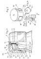
- Fig. 1
- eine teilweise geschnittene Seitenansicht eine weitere Ausführungsform eines Indikators für Druckluftflaschen mit Indikatorplättchen,
- Fig. 2
- eine teilweise geschnittene Seitenansicht einer weiteren Ausführungsform des Indikators für Druckluftflaschen mit einem Indikatorelement,
- Fig. 3
- in einer vergrößerten Einzeldarstellung das Indikatorelement,
- Fig. 4
- in einer verkleinerten Darstellung das Indikatorelement gemäß Fig. 3 von oben, und
- Fig. 5
- in einer senkrechten Schnittdarstellung ein Detail der Fig. 2.
- Die in Fig. 1 dargestellte Ausführungsform weist an der Druckluftflasche 50 eine Öffnung 51 auf, die mit einer Metallfolie 52 versehen ist, die mit dem oben umlaufenden Rand 53 der Gewindeöffnung 51 fest verbunden ist. Auf dem Gewinde 54 der Gewindeöffnung 51 ist eine verschlußkappe 55 aufgeschraubt. Diese Verschlußkappe 55 weist mittig eine von innen nach außen enger werdende zweistufige Durchgangsbohrung 56 auf. In der breitesten Stufe 57 der Durchgangsbohrung 56 ist ein zylindrisches Element 58 gelagert, das auf der Metallfolie 52 auf' liegt. Dieses zylindrische Element 58 weist mittig ein zweites zylindrisches Element 59 auf, das den gleichen Durchmesser hat wie der engste Teil der Durchgangsbohrung 56. Im mittigen Teil 60 der Durchgangsbohrung 56 liegt eine Spiralfeder 61, die das zweite zylindrische Element 59 umgibt und sich am zylindrischen Element 58 und der Verschlußkappe 55 abstützt. Im befüllten Zustand ist die Metallfolie 52 plan, so daß das zweite zylindrische Element 59 bündig mit der Verschlußkappe 55 abschließt. Auf der Kreisfläche 62 des zweiten Elements 59, die zylindrisch in der Durchgangsbohrung 56 sichtbar ist, ist ein Indikatorplättchen 63 aufgeklebt, das einen größeren Durchmesser aufweist als die Durchgangsbohrung 56. Im unbefüllten Zustand der Druckluftflasche 50 ist die Metallfolie 52 nach innen gewölbt, so daß sich die zylindrischen Elemente 58 und 59 in Richtung der Druckluftflasche 50, unter dem Einfluß der Spiralfeder 61, bewegt haben und das Indikatorplättchen 63 abgerissen ist. Die rechte Seite der Figur 2 gibt den ungefüllten und die linke Seite den befüllten Zustand wieder. In den Fig. 2-5 ist eine weitere Ausführungsform des Indikators dargestellt, die in ihrem Grundaufbau der Ausführungsform nach Fig. 1 ähnlich ist. Auch hierbei weist die Druckluftflasche 50 eine Öffnung 51 auf, die mit einer Metallfolie 52 fest verschlossen ist, die mit dem oben umlaufenden Rand 53 der flaschenhalsartigen Öffnung 51 fest verbunden ist. Auf das Außengewinde 54 der flaschenhalsartigen Öffnung 51 ist eine Verschlußkappe 55 aufgeschraubt. Die Metallfolie ist dabei so angeordnet, daß keinerlei Verbindung des Druckraums nach außen über die Öffnung 51 besteht, da die Metallfolie den flexiblen Teil der Wandung der Druckluftflasche 50 bildet. Die Verschlußkappe 55 weist eine die Öffnung 51 und damit die Metallfolie 52 übergreifende Deckelfläche 65 auf, in der mittig eine von innen nach außen zweistufig enger werdende Durchgangsbohrung 66 ausgebildet ist. In der unteren breiteren Stufe 67 der Durchgangsbohrung 66 ist ein erstes zylindrisches Element 68 gehalten, das auf der Metallfolie 52 fest aufliegt. Die Metallfolie wird dabei von dem ersten zylindrischen Element 68 und der Deckelfläche 65 vollständig abgedeckt und abgestützt. Das erste zylindrische Element 68 trägt mittig ein zweites zylindrisches Element 69. Dieses zweite zylindrische Element 69 weist einen kleineren Durchmesser auf wie die engere Stufe 70 der Durchgangsbohrung 66 in der Deckelfläche 65. Um das zweite zylindrische Element 69 herum ist eine Spiralfeder 71 angeordnet.
- Die seitliche Wandung 72 der Verschlußkappe 55 ist über die Deckelfläche hinauskragend ausgebildet und umschließt einen zylindrischen oben offenen Innenraum 73.
- Dieser ist durch eine oben auf den umlaufenden Rand der seitlichen Wandung 72 aufgelegte Verschlußplatte 74 abgedeckt, die fest mit der seitlichen Wandung 72 verbunden ist, indem sie mit einem nach unten auskragenden Abschnitt 75 mit der seitlichen Wandung 72 verschraubt ist. In dem Innenraum 73 ist ein Indikatorelement 76 angeordnet, das zylindrisch geformt ist. In der Verschlußplatte 74 ist eine zweistufig enger werdende Durchgangsöffnung 77 ausgebildet, wobei der Außendurchmesser des Indikatorelements 76 dem Innendurchmesser des engeren Teils 78 der Durchgangsöffnung 77 entspricht, während der untere zweite Teil 79 der Durchgangsbohrung einen größeren Innendurchmesser aufweist.
- Das Indikatorelement 76 ist als topfartiger Hohlkörper ausgebildet und weist vier in der Seitenwand angeordnete Sperrelemente 80,81,82,83 auf. Diese sind durch in Längsrichtung des Indikatorelements verlaufende Einschnitte so von der Seitenwand 74 des Indikatorelements getrennt, daß sie nur noch über eine Verbindungslinie 85 mit dem Indikatorelement verbunden sind und daher elastisch an diesem angeordnet sind. Jedes Sperrelement weist dabei an seinem freien Ende eine Erweiterung auf, die außenseitig eine Anlagefläche 86 trägt. Der Übergang zwischen der ersten Stufe 78 und der zweiten Stufe 79 der Durchgangsbohrung 77 in der Verschlußplatte 74 ist als Schrägfläche 87 ausgebildet, die in ihrer Formgebung mit der Anlagefläche 86 jedes Sperrelements 80,81,82,83 korrespondiert. Der untere Rand 78 des Indikatorelements 76 ist auf der Spiralfeder 71 abgestützt, die sich wiederum auf dem ersten zylindrischen Element 68 abstützt. Die Spiralfeder 71 drückt daher von unten gegen das Indikatorelement 76, das die Durchgangsbohrung 77 in der Verschlußplatte 74 durchtreten würde, wenn nicht die Anlageflächen 86 der Sperrelemente 80,81,82,83 an der Schrägfläche 87 in der Verschlußplatte 74 anliegen würden und somit das Indikatorelement 76 zurückhalten würden. Die Sperrelemente 80,81,82,83 sind dabei bei gefüllter Druckluftflasche gehindert, nach innen zu verschwenken und das Indikatorelement 76 freizugeben, da das Indikatorelement 76 hohlzylindrisch ausgebildet ist und in das Indikatorelement das zweite zylindrische Element 69 wie ein Kolben eingesteckt ist. In der Stellung, in der sich das zweite zylindrische Element 69 bei ordnungsgemäß befüllter Druckluftflasche 50 befindet, ist das zweite zylindrische Element 69 soweit in das Indikatorelement 76 eingeschoben, daß die Sperrelemente 80,81,82,83 gegen eine Verschwenkung nach innen blockiert sind. Diese können dann nicht aus ihrer sperrenden und mit der Anlagefläche 86 den von der Schrägfläche 87 gebildeten Halterungsabschnitt in der Verschlußplatte 74 hintergreifenden Stellung herausschwenken, so daß das Indikatorelement 76 fest in der Verschlußplatte 74 gehalten wird.
- Wenn jedoch aus irgendwelchen Gründen der Druck in der Druckflasche 50 abfällt und sich unter Einwirkung der Spiralfeder 71 eine Verformung der Metallfolie 52 zum Innenraum 19a hin ergibt, fährt das zweite zylindrische Element 68 aus dem Indikatorelement 76 in der in der Zeichnung mit X bezeichneten Richtung heraus. In diesem Moment können die Sperrelemente 80,81,82,83 sich nach innen in Y-Richtung in den Innenraum des Indikatorelementes 76 bewegen und das Indikatorelement 76 ist in der Verschlußplatte 74 nicht mehr gehaltert. Unter Einwirkung der Kraft F der Spiralfeder 71 wird das Indikatorelement 76 durch die Durchgangsöffnung 77 in der Verschlußplatte 74 hindurchgeschoben. Je nach Dimensionierung der Spiralfeder 71 ragt das Indikatorelement entweder hervor oder es wird ganz ausgeworfen. Es ist auf jeden Fall sofort von außen erkennbar, daß der Druck unter eine bestimmte vorgegebene Grenze gefallen ist.
Claims (5)
- Indikator (100) an einer Druckluftflasche (50) od. dgl. zur Anzeige des Unterschreitens eines definierten Druckes in der Druckluftflasche (50), wobei mindestens ein bestimmter Teil (52) der Wandung der Druckluftflasche (50) derart ausgelegt ist, daß dieser flexibel ist, so daß dieser Teil der Wandung bei unterschiedlichen Drücken bestimmten unterschiedlichen Verformungen unterliegt, und ein Indikatorelement (63; 76) vorgesehen ist, das derart mit dem flexiblen Teil (52) der Wandung der Druckluftflasche (50) verbunden ist, daß es abhängig von der Verformung des flexiblen Teils (52) unterschiedliche Stellungen einnimmt,
dadurch gekennzeichnet,
daß die Druckluftflasche (50) eine flaschenhalsartige Öffnung (51) mit einem Außengewinde (54) aufweist, die mit einer Metallfolie (52) verschlossen ist, die mit dem oben umlaufenden Rand (53) der Öffnung (51) fest verbunden ist, wobei auf das Gewinde (54) der Gewindeöffnung (51) eine Verschlußkappe (55) aufgeschraubt ist, daß die Verschlußkappe (55) mittig eine von innen nach außen zweistufig enger werdende Durchgangsbohrung (56; 66) aufweist, wobei in der breitesten Stufe (57; 67) der Durchgangsbohrung (56; 66) ein erstes zylindrisches Element (58; 68) eingelegt ist, das auf der Metallfolie (52) aufliegt und mittig ein zweites zylindrisches Element (59; 69) aufweist, das den gleichen Durchmesser hat wie der engste Teil der Durchgangsbohrung (56; 66), wobei die Metallfolie (52), die den flexiblen Teil der Wandung der Druckluftflasche (50) bildet, in unbefülltem Zustand der Druckluftflasche (50) zum Innenraum (51) der Druckluftflasche (50) gewölbt ist, so daß das zweite zylindrische Element (59; 69) das Indikatorelement (63; 76) freigibt bzw. vom Indikatorelement (63; 76) getrennt wird. - Indikator nach Anspruch 1,
dadurch gekennzeichnet,
daß im mittigen Teil (60) der Durchgangsbohrung (56) eine Spiralfeder (61) eingelegt ist, die das zylindrische Element (59) umgibt und sich am zylindrischen Element (58) und der Verschlußkappe (55) abstützt und daß das zweite zylindrische Element (59) derart in seiner Länge bemessen ist, daß die aus der Durchgangsbohrung (56) sichtbare Kreisfläche (62) im unbefüllten Zustand der Druckluftflasche (50) bündig mit der Verschlußkappe (55) abschließt, wobei auf die Kreisfläche (62) als Indikatorelement ein Indikatorplättchen (63) aufgeklebt ist, das einen größeren Durchmesser aufweist als die Durchgangsbohrung (56). - Indikator nach Anspruch 1,
dadurch gekennzeichnet,
daß die seitliche Wandung (72) der Verschlußkappe (55) über die die Durchgangsbohrung (66) aufweisende Deckelfläche (65) hinauskragend ausgebildet ist, so daß ein Innenraum (73) gebildet ist, der durch eine Verschlußplatte (74) abgedeckt ist, die fest mit der seitlichen Wandung (72) der Verschlußkappe (55) verbunden ist und die eine mittige Durchgangsbohrung (77) aufweist, wobei in den Innenraum (73) ein zylindrisch geformtes Indikatorelement (76) eingesetzt ist, dessen Außendurchmesser dem der Durchgangsbohrung (77) in der Verschlußplatte (74) entspricht und das mindestens einseitig auskragende Sperrelement (80,81,82,83) aufweist, das elastisch an dem Indikatorelement befestigt und eine einen Halteabschnitt (87) der Verschlußplatte (74) hintergreifende Anlagefläche (86) aufweist und in eine Freigabestellung verschwenkbar angeordnet ist, wobei jedes Sperrelement (80,81,82,83) durch das zweite zylindrische Element (69) in seiner das Indikatorelement (76) halternden Stellung blockierbar ist, und daß sich zwischen dem ersten zylindrischen Element (68) und dem Indikatorelement (76) eine Spiralfeder (71) befindet, durch die ständig Druck auf das Indikatorelement (76) ausgeübt wird, das jedoch durch das oder die Sperrelemente (80,81,82,83) bei befüllter Druckluftflasche gehalten wird. - Indikator nach Anspruch 2 oder 3,
dadurch gekennzeichnet,
daß die Durchgangsbohrung (77) in der Verschlußplatte (74) zweistufig enger werdend ausgebildet ist, daß der Außendurchmesser des Indikatorelementes (76) dem engeren Teil (78) der Durchgangsbohrung (77) in der Verschlußplatte (74) entspricht und daß der Übergang zwischen dem weiteren Teil (79) der Durchgangsbohrung (77) und dem engeren Teil (78) der Durchgangsbohrung (77) als Schrägfläche (87) ausgebildet den Halteabschnitt bildet, auf dem sich die Anlagefläche (86) jedes Sperrelementes (80,81,82,83) in seiner das Indikatorelement (76) halternden Stellung abstützt. - Indikator nach einem der Ansprüche 2 bis 4,
dadurch gekennzeichnet,
daß vier Sperrelemente (80,81,82,83) vorgesehen sind, die symmetrisch an dem Indikatorelement angeordnet sind, von denen jedes als einen Abschnitt der Außenwandung (84) des hohlzylindrischen Indikatorelementes (76) bildender, aus der Wandungsebene verschwenkbarer Sperrkörper mit einem an einer freien Endkante (88) angeordnetem Anlageteil (89) mit der Anlagefläche (86) ausgebildet ist.
Applications Claiming Priority (2)
| Application Number | Priority Date | Filing Date | Title |
|---|---|---|---|
| DE9303295U DE9303295U1 (de) | 1993-03-06 | 1993-03-06 | Indikator für Druckluftflaschen |
| DE9303295U | 1993-03-06 |
Publications (2)
| Publication Number | Publication Date |
|---|---|
| EP0615093A1 EP0615093A1 (de) | 1994-09-14 |
| EP0615093B1 true EP0615093B1 (de) | 1997-09-17 |
Family
ID=6890284
Family Applications (1)
| Application Number | Title | Priority Date | Filing Date |
|---|---|---|---|
| EP94102633A Expired - Lifetime EP0615093B1 (de) | 1993-03-06 | 1994-02-22 | Indikator für Druckluftflaschen |
Country Status (4)
| Country | Link |
|---|---|
| US (1) | US5493900A (de) |
| EP (1) | EP0615093B1 (de) |
| AT (1) | ATE158393T1 (de) |
| DE (2) | DE9303295U1 (de) |
Families Citing this family (4)
| Publication number | Priority date | Publication date | Assignee | Title |
|---|---|---|---|---|
| DE19731991A1 (de) * | 1997-07-05 | 1997-12-18 | Wolfgang Merkel | Füllstandanzeiger für Gasflaschen |
| FR2796125B1 (fr) * | 1999-07-09 | 2001-08-10 | Liotard Metallurg | Reservoir resistant a l'eclatement dont une cloison se rompt au-dela d'une certaine pression |
| US6589087B2 (en) | 2001-09-07 | 2003-07-08 | Halkey-Roberts Corporation | Automatic inflator with status indicator |
| CN2544359Y (zh) * | 2002-06-07 | 2003-04-09 | 宋有洲 | 室内防暴捕捉器 |
Family Cites Families (13)
| Publication number | Priority date | Publication date | Assignee | Title |
|---|---|---|---|---|
| DE216532C (de) * | ||||
| DE205996C (de) * | ||||
| FR1258750A (fr) * | 1959-06-09 | 1961-04-14 | Pyrene Co Ltd | Perfectionnement apporté aux récipients sous pression |
| US3950983A (en) * | 1973-07-05 | 1976-04-20 | Treadwell Corporation | Air leak detector |
| US4023415A (en) * | 1974-04-18 | 1977-05-17 | G. E. Garcia | Pressure monitoring device |
| FR2429601A1 (fr) * | 1978-06-30 | 1980-01-25 | Procedes Modernes Impression | Dispositif de securite pour extincteur d'incendie |
| DE3035766C2 (de) * | 1980-09-23 | 1985-08-14 | Vtg Vereinigte Tanklager Und Transportmittel Gmbh, 2000 Hamburg | Warneinrichtung zur Anzeige einer Druckerhöhung in einem Behälter |
| FR2555290B1 (fr) * | 1983-11-21 | 1987-11-27 | Clesse Mandet Sa | Dispositif de visualisation de l'etat de charge d'un poste d'alimentation en gaz |
| US4528840A (en) * | 1984-02-06 | 1985-07-16 | Wass Lloyd G | Hydrostatic test stand |
| NO155717C (no) * | 1984-07-13 | 1987-05-13 | Moss Glasvaerk As | Innretning for pneumatisk kontroll av beholdere med hensyn til tetthet og sperrende defekter. |
| GB2164453B (en) * | 1984-09-10 | 1989-05-24 | Trace Societe De Traitement Au | Apparatus for leak testing at least one wall portion and/or a volume delimited by said wall portion |
| US5027740A (en) * | 1990-01-19 | 1991-07-02 | Robert Kramer | Valve cap pressure drop indicator |
| US5105653A (en) * | 1991-02-15 | 1992-04-21 | Konter Richard J | Pressure testing device for vehicle radiators and cooling systems |
-
1993
- 1993-03-06 DE DE9303295U patent/DE9303295U1/de not_active Expired - Lifetime
-
1994
- 1994-02-03 US US08/191,859 patent/US5493900A/en not_active Expired - Lifetime
- 1994-02-22 EP EP94102633A patent/EP0615093B1/de not_active Expired - Lifetime
- 1994-02-22 AT AT94102633T patent/ATE158393T1/de not_active IP Right Cessation
- 1994-02-22 DE DE59404060T patent/DE59404060D1/de not_active Expired - Fee Related
Also Published As
| Publication number | Publication date |
|---|---|
| EP0615093A1 (de) | 1994-09-14 |
| DE9303295U1 (de) | 1994-07-07 |
| ATE158393T1 (de) | 1997-10-15 |
| US5493900A (en) | 1996-02-27 |
| DE59404060D1 (de) | 1997-10-23 |
Similar Documents
| Publication | Publication Date | Title |
|---|---|---|
| AT409121B (de) | Aufblasvorrichtung, insbesondere für eine rettungsweste | |
| DE3812552C1 (de) | ||
| DE612136C (de) | Sicherheitsventil fuer Druckgasbehaelter | |
| EP0535299B1 (de) | Vorrichtung zum Aufblasen, insbesondere eines Behälters oder eines Schwimmkörpers eines Rettungsgerätes | |
| EP1423671A1 (de) | Druckanzeigevorrichtung | |
| EP0615093B1 (de) | Indikator für Druckluftflaschen | |
| EP1998984B8 (de) | Kaltgasgenerator | |
| EP1109684B1 (de) | Selbstschliessende luftfederanordnung | |
| EP0581011B1 (de) | Behälter mit Druckausgleichseinrichtung | |
| DE102020101756B4 (de) | Berstschutzeinheit | |
| EP0004595A2 (de) | Steuerbares Ventil für eine Brandlöschanlage | |
| DE2324170A1 (de) | Behaelterverschluss mit druckausgleichventil, insbesondere fuer kraftfahrzeugkraftstoffbehaelter | |
| DE9305416U1 (de) | Sicherheitsverschluß für Behälter | |
| EP3805627A1 (de) | Schutzvorrichtung für druckgasbehälter | |
| DE2706564C2 (de) | Abgabekappe für Aerosoldruckdose | |
| EP0788815A2 (de) | Druckhebel-Ventil für Dauerdruck-Feuerlöscher | |
| DE1930185A1 (de) | Fluessigkeitsbehaelter mit einem Dom | |
| DE7819791U1 (de) | Absperrarmatur fuer druckgasbehaelter | |
| DE2238356A1 (de) | Fuellventil mit verschiebbarem ventilkoerper fuer hydropneumatische federungen von kraftfahrzeugen | |
| EP4574221A1 (de) | Automatisches ventil für brandbekämpfungs- und brandunterdrückungssysteme | |
| DE1064306B (de) | Gasdruckregler und Gasflaschenventil | |
| DE3200929C2 (de) | Druckminderer | |
| AT7875B (de) | Luftventil für Radreifen und dergl. | |
| CH269281A (de) | Ventileinrichtung mit einer Sicherheitseinrichtung mit Zerreissmembran für Druckbehälter. | |
| WO1993023308A1 (de) | Schraubkappe zum verschliessen einer flasche oder dergleichen |
Legal Events
| Date | Code | Title | Description |
|---|---|---|---|
| PUAI | Public reference made under article 153(3) epc to a published international application that has entered the european phase |
Free format text: ORIGINAL CODE: 0009012 |
|
| AK | Designated contracting states |
Kind code of ref document: A1 Designated state(s): AT BE CH DE DK FR GB IT LI NL SE |
|
| 17P | Request for examination filed |
Effective date: 19940725 |
|
| 17Q | First examination report despatched |
Effective date: 19950502 |
|
| GRAG | Despatch of communication of intention to grant |
Free format text: ORIGINAL CODE: EPIDOS AGRA |
|
| GRAH | Despatch of communication of intention to grant a patent |
Free format text: ORIGINAL CODE: EPIDOS IGRA |
|
| GRAH | Despatch of communication of intention to grant a patent |
Free format text: ORIGINAL CODE: EPIDOS IGRA |
|
| GRAA | (expected) grant |
Free format text: ORIGINAL CODE: 0009210 |
|
| AK | Designated contracting states |
Kind code of ref document: B1 Designated state(s): AT BE CH DE DK FR GB IT LI NL SE |
|
| PG25 | Lapsed in a contracting state [announced via postgrant information from national office to epo] |
Ref country code: NL Free format text: LAPSE BECAUSE OF FAILURE TO SUBMIT A TRANSLATION OF THE DESCRIPTION OR TO PAY THE FEE WITHIN THE PRESCRIBED TIME-LIMIT Effective date: 19970917 Ref country code: IT Free format text: LAPSE BECAUSE OF FAILURE TO SUBMIT A TRANSLATION OF THE DESCRIPTION OR TO PAY THE FEE WITHIN THE PRESCRIBED TIME-LIMIT;WARNING: LAPSES OF ITALIAN PATENTS WITH EFFECTIVE DATE BEFORE 2007 MAY HAVE OCCURRED AT ANY TIME BEFORE 2007. THE CORRECT EFFECTIVE DATE MAY BE DIFFERENT FROM THE ONE RECORDED. Effective date: 19970917 Ref country code: FR Free format text: LAPSE BECAUSE OF FAILURE TO SUBMIT A TRANSLATION OF THE DESCRIPTION OR TO PAY THE FEE WITHIN THE PRESCRIBED TIME-LIMIT Effective date: 19970917 Ref country code: DK Free format text: LAPSE BECAUSE OF NON-PAYMENT OF DUE FEES Effective date: 19970917 |
|
| REF | Corresponds to: |
Ref document number: 158393 Country of ref document: AT Date of ref document: 19971015 Kind code of ref document: T |
|
| REG | Reference to a national code |
Ref country code: CH Ref legal event code: EP |
|
| GBT | Gb: translation of ep patent filed (gb section 77(6)(a)/1977) |
Effective date: 19970919 |
|
| REF | Corresponds to: |
Ref document number: 59404060 Country of ref document: DE Date of ref document: 19971023 |
|
| PG25 | Lapsed in a contracting state [announced via postgrant information from national office to epo] |
Ref country code: SE Effective date: 19971217 |
|
| EN | Fr: translation not filed | ||
| PG25 | Lapsed in a contracting state [announced via postgrant information from national office to epo] |
Ref country code: LI Free format text: LAPSE BECAUSE OF NON-PAYMENT OF DUE FEES Effective date: 19980228 Ref country code: CH Free format text: LAPSE BECAUSE OF NON-PAYMENT OF DUE FEES Effective date: 19980228 Ref country code: BE Free format text: LAPSE BECAUSE OF NON-PAYMENT OF DUE FEES Effective date: 19980228 |
|
| NLV1 | Nl: lapsed or annulled due to failure to fulfill the requirements of art. 29p and 29m of the patents act | ||
| PLBE | No opposition filed within time limit |
Free format text: ORIGINAL CODE: 0009261 |
|
| STAA | Information on the status of an ep patent application or granted ep patent |
Free format text: STATUS: NO OPPOSITION FILED WITHIN TIME LIMIT |
|
| BERE | Be: lapsed |
Owner name: BERNHARDT APPARATEBAU G.M.B.H. U. CO. Effective date: 19980228 |
|
| 26N | No opposition filed | ||
| REG | Reference to a national code |
Ref country code: CH Ref legal event code: PL |
|
| REG | Reference to a national code |
Ref country code: GB Ref legal event code: IF02 |
|
| PGFP | Annual fee paid to national office [announced via postgrant information from national office to epo] |
Ref country code: GB Payment date: 20050211 Year of fee payment: 12 |
|
| PGFP | Annual fee paid to national office [announced via postgrant information from national office to epo] |
Ref country code: AT Payment date: 20050218 Year of fee payment: 12 |
|
| PGFP | Annual fee paid to national office [announced via postgrant information from national office to epo] |
Ref country code: DE Payment date: 20050421 Year of fee payment: 12 |
|
| PG25 | Lapsed in a contracting state [announced via postgrant information from national office to epo] |
Ref country code: GB Free format text: LAPSE BECAUSE OF NON-PAYMENT OF DUE FEES Effective date: 20060222 Ref country code: AT Free format text: LAPSE BECAUSE OF NON-PAYMENT OF DUE FEES Effective date: 20060222 |
|
| PG25 | Lapsed in a contracting state [announced via postgrant information from national office to epo] |
Ref country code: DE Free format text: LAPSE BECAUSE OF NON-PAYMENT OF DUE FEES Effective date: 20060901 |
|
| GBPC | Gb: european patent ceased through non-payment of renewal fee |
Effective date: 20060222 |