EP0615205A2 - Bildverarbeitungsvorrichtung und Aufzeichnungs-/Wiedergabegerät - Google Patents
Bildverarbeitungsvorrichtung und Aufzeichnungs-/Wiedergabegerät Download PDFInfo
- Publication number
- EP0615205A2 EP0615205A2 EP94103519A EP94103519A EP0615205A2 EP 0615205 A2 EP0615205 A2 EP 0615205A2 EP 94103519 A EP94103519 A EP 94103519A EP 94103519 A EP94103519 A EP 94103519A EP 0615205 A2 EP0615205 A2 EP 0615205A2
- Authority
- EP
- European Patent Office
- Prior art keywords
- pixel
- calculating
- curvature
- value
- recording
- Prior art date
- Legal status (The legal status is an assumption and is not a legal conclusion. Google has not performed a legal analysis and makes no representation as to the accuracy of the status listed.)
- Granted
Links
Images




Classifications
-
- G—PHYSICS
- G06—COMPUTING OR CALCULATING; COUNTING
- G06T—IMAGE DATA PROCESSING OR GENERATION, IN GENERAL
- G06T5/00—Image enhancement or restoration
- G06T5/20—Image enhancement or restoration using local operators
-
- Y—GENERAL TAGGING OF NEW TECHNOLOGICAL DEVELOPMENTS; GENERAL TAGGING OF CROSS-SECTIONAL TECHNOLOGIES SPANNING OVER SEVERAL SECTIONS OF THE IPC; TECHNICAL SUBJECTS COVERED BY FORMER USPC CROSS-REFERENCE ART COLLECTIONS [XRACs] AND DIGESTS
- Y10—TECHNICAL SUBJECTS COVERED BY FORMER USPC
- Y10S—TECHNICAL SUBJECTS COVERED BY FORMER USPC CROSS-REFERENCE ART COLLECTIONS [XRACs] AND DIGESTS
- Y10S977/00—Nanotechnology
- Y10S977/84—Manufacture, treatment, or detection of nanostructure
- Y10S977/849—Manufacture, treatment, or detection of nanostructure with scanning probe
- Y10S977/85—Scanning probe control process
Definitions
- the present invention relates to an image processing apparatus and a recording/reproducing apparatus and, more particularly, a recording/reproducing apparatus for recording information on a recording medium and reproducing the recorded information as image information using a signal obtained by a physical interaction between the recording medium and a probe electrode upon two-dimensional scanning of the probe electrode relative to the recording medium, and an image processing apparatus suitable for this recording/reproducing apparatus.
- the recording capacity of data required for a recording/reproducing apparatus tends to increase.
- the size of the unit of recording is reduced, and the density of the unit of recording must be increased.
- the size of the unit of recording is reduced to about 1 ⁇ m2.
- STM scanning tunnel microscope
- the scanning tunnel microscope utilizes the flow of a tunnel current (i.e., a signal obtained by a physical interaction between a probe electrode (metal probe) and a conductive material) between the probe electrode and the conductive material while a voltage is kept applied between the probe electrode and the conductive material.
- the tunnel current is very sensitive to a change in distance between the probe electrode and the conductive material.
- the probe electrode is two-dimensionally scanned relative to the surface of the conductive material so as to keep the average distance between the probe electrode and the conductive material or the tunnel current constant, thereby obtaining surface information of the real space of the conductive material.
- the resolution in the longitudinal direction of the conductive material is 10 nm or less.
- a material a thin film layer of ⁇ electron organic compound or chalcogen compound having a memory effect for voltage and current switching characteristics is used as a recording medium to allow recording/reproduction of information in recording units of 0.01 ⁇ m2 or less.
- a technique for changing the surface shape/state of a recording medium using an electromagnetic wave such as an electron beam or light is used to allow information recording/reproduction at a recording density almost equal to that of the state-of-the-art optical recording although the unit of recording increases due to the limitations of the degree of focusing of an electron beam or the like.
- the S/N ratio of the reproduced signal decreases and the error rate increases due to the three-dimensional pattern formed on the recording surface.
- the three-dimensional pattern avoids an increase in recording capacity.
- a method of growing a monocrystalline Au thin film on the cleavage surface of mica or the like to obtain a smooth surface can be used. Even if a recording medium obtained by this method is used, however, the shape of a recording bit is changed by a step or ridge on the atomic order through a three-dimensional pattern having a size almost equal to that of a recording bit on the order of 10 nm or less in diameter. As a result, the S/N ratio of the reproduced signal decreases, and the error ratio increases.
- Filtering in a frequency range belonging to a linear filter may be used as a method of reducing noise of the reproduced signal.
- this method is effective only if the frequency bands of a signal and noise in the reproduction mode are known and can be linearly separated.
- the frequency bands for individual shapes are known, the positions of recording bits are unknown.
- the step or ridge has a portion (i.e., an edge) having a large differential coefficient on the spatial coordinate system. For this reason, these frequency components extend through the entire frequency range.
- the compact recording bit frequency components spatially extend to the entire range. Therefore, these frequency components cannot be separated into bands on the frequency space.
- the position of the step or ridge cannot be specified, and it is therefore difficult to perform extraction using template matching of a power spectrum.
- a technique belonging to the field of nonlinear filters is available as a conventional image processing technique having spatial correlation as its most important factor.
- this technique an extraction image obtained by extracting the step or ridge from an image is prepared, and the extraction image is subtracted from the original image to remove the step or ridge. Since the technique for extracting only the step or ridge from the image, however, has a repetitive and serial processing form and strongly depends on the number of pixels, this technique is very disadvantageous in a recording/reproducing apparatus whose read rate is most important.
- an image information processing apparatus for processing image information, comprising total curvature calculating means for calculating a total curvature at each pixel of the image information, mean curvature calculating means for calculating a mean curvature at each pixel of the image information, logical product computing means for computing a logical product of outputs from the total curvature calculating means and the mean curvature calculating means, and a median filter for filtering an output from the logical product computing means.
- an image information processing apparatus for processing image information, comprising means for calculating a numerator of a total curvature at each pixel of the image information, means for calculating a numerator of a mean curvature at each pixel of the image information, logical product computing means for computing a logical product of outputs from the means for calculating the numerator of the total curvature and the means for calculating the numerator of the mean curvature, and a median filter for filtering an output from the logical product computing means.
- an information recording/reproducing apparatus for reproducing information from a recording medium by utilizing a physical interaction between a probe and the recording medium while the probe is two-dimensionally scanned relative to the recording medium, comprising total curvature calculating means for calculating a total curvature at each pixel of surface information of the recording medium, the surface information being detected by the physical interaction, mean curvature calculating means for calculating a mean curvature at each pixel of the surface information, logical product computing means for computing a logical product of outputs from the total curvature calculating means and the mean curvature calculating means, and a median filter for filtering an output from the logical product computing means, wherein an output from the medium filter is reproduced information.
- an information recording/reproducing apparatus for reproducing information from a recording medium by utilizing a physical interaction between a probe and the recording medium while the probe is two-dimensionally scanned relative to the recording medium, comprising means for calculating a numerator of a total curvature at each pixel of surface information of the recording medium, the surface information being detected by the physical interaction, means for calculating a numerator of a mean curvature at each pixel of the surface information, logical product computing means for computing a logical product of outputs from the means for calculating the numerator of the total curvature and the means for calculating the numerator of the mean curvature, and a median filter for filtering an output from the logical product computing means, wherein an output from the median filter is reproduced information.
- two-dimensional image information is regarded as a function defined on a two-dimensional plane, and a total curvature of the function at each point (each pixel of image information) on the two-dimensional plane is obtained.
- a point at which the sign of the total curvature is positive is detected as an elliptic point, and a point at which the sign of the total curvature is not positive is detected as a parabolic or hyperbolic point.
- the mean curvature of functions at points on the two-dimensional plane is obtained.
- An elliptic point at which the mean curvature is negative has a convex shape on the recording surface
- an elliptic point at which the mean curvature is positive has a concave shape on the recording surface. If it is known that an elliptic point on the convex curve on the recording surface exhibits necessary information, a logical product of an output signal from the total curvature calculating means and an output signal from the mean curvature calculating means is computed to remove error information included in the image information, thereby extracting only necessary information.
- An output signal from the logical product computing means is input to a median filter to remove noise caused by discretization of spatial coordinates.
- the recording/reproducing apparatus of the first embodiment of the present invention includes image information forming means for calculating the total and mean curvatures at each pixel of the image information reproduced from a signal obtained by the physical interaction to form new image information.
- the recording bit becomes an upwardly curved convex surface (to be referred to as an ON bit hereinafter), i.e., a set of upward convex elliptic points or a downwardly curved concave surface (to be referred to as an OFF bit hereinafter), i.e., a set of downwardly concave elliptic points.
- the parabolic points, the hyperbolic points, the upwardly concave elliptic points (or upwardly concave elliptic points) on the recording surface are removed to extract only the recording bit, thereby obtaining new image information.
- Each of the total and mean curvatures at each pixel can be obtained by calculating the first and second fundamental quantities at each pixel. Since the first and second fundamental quantities are locally defined, the processing form has parallel processing characteristics independently of the number of pixels.
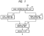
- Fig. 1 is a block diagram showing the image processing apparatus according to the first embodiment of the present invention.
- An image processing apparatus 100 includes an image information input unit 101, a total curvature calculating unit 102, a mean curvature calculating unit 103, a logical product computing unit 104, and a median filter 105.
- the total curvature calculating unit 102 calculates a total curvature K at each pixel using an image information signal supplied from the image information unit 101. The value of each pixel is set to "1" if the total curvature K is positive and set to "0" otherwise, thereby performing nonlinear binarization of each pixel represented by the image information signal.
- the mean curvature calculating unit 103 calculates a mean curvature H at each pixel using an image information signal supplied from the image information unit 101.
- the logical product computing unit 104 computes the logical product of an output signal from the total curvature calculating unit 102 and an output signal from the mean curvature calculating unit 103 in units of pixels.
- the median filter 105 removes isolated points included in an output signal from the logical product computing unit 104.
- the recording bit is regarded to have a single peak, as shown in Fig. 2C, in accordance with the method of changing the surface shape of the recording medium using the principle of the scanning tunnel microscope or the method of changing the surface state of the recording medium using the electromagnetic wave such as an electron beam or light.
- the recording bit is regarded to be constituted by elliptic points near at least the maximum value of the single peak.
- the "shape having the single peak" is a shape whose height monotonously decreases away from the position of the maximum value within a certain range.
- the total curvature K, the elliptic point, the parabolic point, and the hyperbolic point have the following relationships:
- x vv is the differential coefficient of second order of x by v
- x u is the differential coefficient of first order of x by u.
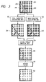
- An original image 200 represented by a contour line and input from the image information input unit 101 is constituted by a combination of an elliptic point area 201 representing a recording bit and a parabolic point area 202 representing a step or ridge.
- a plurality of parabolic point areas 202 interact with each other or spatial coordinates as an image definition area is subjected to discretization to obtain a hyperbolic point area 203.
- an image signal representing the original image 200 is input to the total curvature calculating unit 102 to obtain a total curvature calculating unit output image 210 in which the parabolic and hyperbolic point areas 202 and 203 serve as isolated points.
- the image signal representing the original image 200 is input to the mean curvature calculating unit 103 to obtain a mean curvature calculating unit output image 220 in which a concave area and a flat area serve as isolated points.
- Output signals from the total curvature calculating unit 102 and the mean curvature calculating unit 103 are input to the logical product computing unit 104 to obtain a logical product computing output image 230 representing the extracted elliptic point area 201 representing the recording bit.
- the logical product computing unit output image 230 also includes the extracted elliptic point area caused by a discretization of the spatial coordinates in addition to the elliptic point area 201 representing the recording bit.
- An output signal from the logical product computing unit 104 is input to the median filter 105 to obtain an elliptic point extraction image 240 representing only the extracted elliptic point area 201 representing the ON bit.
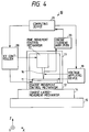
- Fig. 4 is a schematic block diagram showing a recording/reproducing apparatus according to the first embodiment of the present invention.
- a recording/reproducing apparatus 10 includes a recording medium 11, a coarse movement control mechanism 12, a housing 13, a coarse large-movement mechanism 14, an antivibration table 15, a probe electrode 16, a fine movement control mechanism 17, an XY controller 18, a voltage applying device 19, a probe current amplifier 20, and a computing device 21.
- the respective constituent components of the recording/reproducing apparatus 10 will be described in detail below.
- the recording medium 11 is obtained by stacking eight squalirium-bis-6-octylazulene layers on a graphite substrate in accordance with the LB method.
- squalirium-bis-6-octylazulene has a memory effect for the voltage and current switching characteristics.
- the recording medium In the initial state, the recording medium is set in a non-recording state (OFF state).
- the recording surface of the recording medium 11 is divided into four general recording areas (first to fourth general recording areas 301 to 304), as shown in Fig. 5. First four position reference pattern areas 311 to 314 are assured to the left of the first to fourth general recording areas 301 to 304.
- the coarse movement control mechanism 12 on which the recording medium 11 is placed has parallel springs using an elastic hinge.
- the coarse movement control mechanism 12 controls coarse movement of the recording medium in the X and Y directions in Fig. 4.
- the housing 13 consists of Invar for supporting the respective structural portions of the recording/reproducing apparatus 10.
- the coarse large-movement mechanism 14 controls coarse large-movement of the recording/reproducing apparatus 10 in the X and Y directions in Fig. 4 in a range falling outside the control range of the coarse movement control mechanism 12.
- the antivibration table 15 on the coarse large-movement mechanism 14 prevents transmission of an external vibration to the recording/reproducing apparatus 10, thereby preventing the operational error of the recording/reproducing apparatus 10 which is caused by the external vibration.
- the probe electrode 16 is used to record and reproduce information.
- the distal end of the probe electrode 16 is obtained by mechanically or electrolytically polishing the distal end of a tungsten stylus to increase the recording and reproduction resolutions.
- the material for the probe electrode 16 may be Pt-Ir or Pt.
- the method of forming the probe electrode 16 is not limited to the above method.
- the fine movement control mechanism 17 to which the probe electrode 16 is attached is constituted using a cylindrical piezoelectric element.
- the fine movement control mechanism 17 finely moves the probe electrode 16 in the Z direction in Fig. 4 to finely adjust the distance between the probe electrode 16 and the recording medium 11.
- the fine movement control mechanism 17 two-dimensionally scans the probe electrode 16 in the X and Y directions in Fig.
- the XY controller 18 drives and controls the coarse movement control mechanism 12 and the fine movement control mechanism 17 in accordance with commands from the computing device 21.
- the XY controller 18 outputs operation voltages representing the drive amounts of the coarse movement control mechanism 12 and the fine movement control mechanism 17 to the coarse movement control mechanism 12 and the fine movement control mechanism 17, respectively.
- the voltage applying device 19 applies a recording voltage, a reproduction voltage, and an erasure voltage between the probe electrode 16 and the recording medium 11 in accordance with commands from the computing device 21.
- the voltage applying device 19 can apply an arbitrary bias voltage of -10 V to +10 V between the probe electrode 16 and the recording medium 11.
- the probe current amplifier 20 detects a current flowing between the probe electrode 16 and the recording medium 11 to amplify the detected current.
- the amplified current is converted into a voltage by the probe current amplifier 20. This voltage is then output from the probe current amplifier 20 to the computing device 21.
- the computing device 21 includes an A/D converter for converting the voltage supplied from the probe current amplifier 20 into a digital signal, a microprocessor for controlling the XY controller 18 and the voltage applying device 19, a position reference memory for storing the position reference on the recording medium 11, a processor for performing pattern recognition of information to be recorded and converting the recognized information into a code, and the image processing circuit (Fig. 1) for forming image information in accordance with the digital signal output from the A/D converter and extracting only the recorded bit area from the formed image information.
- the position reference pattern is recorded in the first to fourth position reference pattern areas 311 to 314 in accordance with the following sequence prior to recording of the information in the first to fourth general recording areas 301 to 304 of the recording medium 11.
- the distal end of the probe electrode 16 on the recording medium is positioned at a position spaced apart from a home position H P of the recording medium 11 by about 200 ⁇ m in the Z direction in Fig. 4 with a precision of ⁇ 10 ⁇ m in accordance with the mechanical precision of the housing 13.
- a bias voltage of 300 mV from the voltage applying device 19 is applied across the probe electrode 16 and the recording medium 11.
- a current flowing across the probe electrode 16 and the recording medium 11 is detected and amplified by the probe current amplifier 20.
- the amplified current is converted into a voltage by the probe current amplifier 20.
- the computing device 21 detects the value of the current flowing across the probe electrode 16 and the recording medium 11 in accordance with the voltage applied from the probe current amplifier 20.
- the computing device 21 drives the coarse movement control mechanism 12 until the value of the detected current becomes 1 pA.
- the distal end of the probe electrode 16 comes close to the recording surface of the recording medium 11 until the value of the current flowing across the probe 16 and the recording medium 11 becomes 1 pA.
- the fine movement control mechanism 17 is driven in the same manner as described above by the computing device 21.
- the distal end of the probe electrode 16 comes close to the recording surface of the recording medium 11 until the value of the current flowing across the probe electrode 16 and the recording medium 11 becomes 1 nA. Thereafter, in an area of the recording medium 11 which is surrounded by a dotted line in Fig. 5, the probe electrode 16 is two-dimensionally driven by the computing device 21.
- a bias voltage of +10 V higher than the threshold voltage of the ON/OFF information of the recording medium 11 from the voltage applying device 19 is applied across the probe electrode 16 and the recording medium 11.
- This portion of the recording medium 11 is set in the recording state (ON state) to record the position reference pattern.
- the fine movement control mechanism 17 is controlled by the computing device 21 so that the average value of the current flowing between the probe electrode 16 and the recording medium 11 is set to 0.9 nA so as to reduce an influence on control of the distance between the probe electrode 16 and the recording medium 11.
- the average distance between the probe electrode 16 and the recording medium 11 is kept constant.
- the position reference patterns are sequentially recorded in the first to fourth position reference pattern areas 311 to 314.
- direction patterns and position patterns 361 to 364 are recorded in the first to fourth position reference pattern areas 311 to 314.
- Three direction patterns 3511 to 3513 recorded in the first position reference pattern 311 are recorded at positions corresponding to three direction patterns 3531 to 3533 recorded in the third position reference pattern area 313.
- Three direction patterns 3521 to 3523 recorded in the second position reference pattern area 312 are recorded at positions corresponding to direction patterns 3541 to 3543 recorded in the fourth position reference pattern area 314.
- first to fourth synchronization patterns 371 to 374 are recorded between the general recording areas 301 to 304 and the position reference patterns 311 to 314.
- Positioning of the probe electrode 16 is performed in accordance with the following sequence.
- the probe electrode 16 is two-dimensionally scanned throughout the recording surface of the recording medium 11.
- the value of a current (this current is generated due to the physical interaction between the probe electrode and the recording medium, and the physical interaction in the present invention is exemplified by a voltage, a magnetic force, light, or the like) flowing between the probe electrode 16 and the recording medium 11 is detected to detect the ON/OFF state of the recording medium, thereby detecting the position reference pattern.
- the position reference patterns are recorded in the units of recording larger than those of information recorded in the general recording areas 301 to 304. For this reason, currents detected in the position reference pattern areas 311 to 314 have frequencies lower than those of the currents detected in the general recording areas 301 to 304. Each detected current is filtered through a bandpass filter to approximately separate the position reference pattern from information.
- the probe electrode 16 is moved to one of the four position reference pattern areas 311 to 314 on the basis of the two-dimensional information of each separated position reference pattern. The probe 16 is then two-dimensionally scanned in a range slightly larger than the position reference pattern area.
- the resultant digital signal obtained by the computing device 21 is stored as two-dimensional information in a memory.
- the three direction patterns 3511 to 3513 and 3531 to 3533 are recorded at positions corresponding to the first and third position reference pattern areas 311 and 313.
- the three direction patterns 3521 to 3523 and 3541 to 3543 are recorded at positions corresponding to the second and fourth position reference pattern areas 312 and 314.
- the scanning direction of the probe electrode 16 can be known by detecting the direction patterns 3511 to 3513 3531 to 3533, 3521 to 3523, and 3541 to 3543.
- Position patterns 361 to 364 are recorded in the first to fourth position reference pattern areas 311 to 314.
- the relative position of the probe electrode 16 can be known. More specifically, each position reference pattern includes direction information and position information. Using the general image processing technique, scanning direction information and position information of the probe electrode 16 can be obtained. In addition, coarse position information of the position reference pattern in a general recording area to be scanned next can be obtained in accordance with the positional relationship between the position reference patterns.
- Information recording is performed in accordance with the following sequence.
- the probe electrode 16 is moved to a portion near, e.g., the first general recording area 301 on the basis of the resultant position information.
- the probe electrode 16 is then two-dimensionally scanned in a range wider than the first general recording area 301.
- information is recorded with the precision of a piezoelectric element at a predetermined recording position of the first general recording area 301 on the basis of the resultant position information.
- Information recorded in the first general recording area 301 is reproduced as follows.
- the probe electrode 16 is two-dimensionally scanned in an entire area next to the synchronization signal of the first synchronization pattern 371, and the resultant two-dimensional information (surface information) obtained by utilizing the physical interaction caused between the probe electrode and the recording medium is divided into units of recording (unit information area), as shown in Figs. 2A to 2C in consideration of other pieces of input information such as the hysteresis of the piezoelectric element and the temperature- and humidity-dependent expansion/contraction of the recording medium 11.
- the above image processing is performed for each unit information area, thereby reproducing information. That is, the image-processed two-dimensional information is regarded as reproduced information.
- the probe electrode 16 is moved to a portion near the second general recording area 302 on the basis of the resultant position information.
- An image processing apparatus utilizes the following two points.
- Two-dimensionally spread image information is defined as a function on a two-dimensional plane.
- the total curvature of the function at each point (each pixel of image information) on the two-dimensional plane is obtained.
- a point having a positive total curvature value is an elliptic point, and a point having a non-positive total curvature value is a parabolic or hyperbolic point.
- the mean curvature of the function at each point on the two-dimensional plane is obtained.
- An elliptic point having a negative mean curvature value is convex on the recording surface, and an elliptic point having a positive mean curvature value is concave on the recording surface.
- the following processing is performed.
- the total and mean curvatures of the function at each point on the two-dimensional plane are represented by the fractional numbers in equations (15) and (16), and the denominators always have positive values. Whether a total curvature value is positive or not can be detected by the sign of its numerator. Whether a mean curvature value is negative or not can be detected by the sign of its numerator. For this reason, the values of the numerators of the total and mean curvature values are obtained in place of obtaining the values of the total and mean curvatures.
- the value of the numerator of the total curvature is obtained by a calculating means for numerator of total curvature, and the value of the numerator of the mean curvature is calculated by a calculating means for numerator of mean curvature.
- a logical product of the outputs from the calculating means for numerators of total and mean curvatures is computed. Noise included in the image information can be eliminated, and only necessary information can be extracted.
- An output signal from a logical product computing means is input to a median filter to remove noise caused by discretization of the spatial coordinates.
- the recording/reproducing apparatus also includes an image information forming means for calculating the values of the numerators of the total and mean curvatures at each pixel of the image information reproduced from a signal obtained by the physical interaction to form image information.
- the recording bit becomes an elliptic point on the curved convex surface on the recording surface.
- the parabolic point, the hyperbolic point, and the elliptic point on the curved concave surface on the recording surface are removed to obtain new information representing only the extracted recording bit.
- the value of the numerator of the total curvature at each pixel and the value of the numerator of the mean curvature thereof can be obtained by calculating the first and second fundamental quantities at each pixel, respectively. Since the first and second fundamental quantities are locally defined, the processing form has excellent parallel processing independent of the number of pixels.
- Fig. 6 is a block diagram showing the image processing apparatus according to the second embodiment of the present invention.
- a calculating unit 402 for numerator of total curvature calculates the value of the numerator of the total curvature at each pixel using an image information signal sent from an image information input unit 101. If the value of the numerator of the total curvature is positive, the value of the corresponding pixel is set to "1"; otherwise, the value is set to "0", thereby nonlinear binarization for each pixel represented by the image information signal.
- a calculating unit 403 for numerator of mean curvature calculates the value of the numerator of the mean curvature at each pixel using the image information signal sent from the image information input unit 101.
- a logical product computing unit 404 computes, for each pixel, the logical product of output signals from the calculating unit 402 for numerator of total curvature and the calculating unit 403 for numerator of mean curvature.
- the total and mean curvatures themselves are not calculated, but only the values of the numerators of the total curvature K and the mean curvature H are calculated. In this case, the values can be obtained by the four fundamental rules of arithmetic.
- the total curvature calculating unit 102 and the mean curvature calculating unit 103 in Fig. 1 can be simplified, and hence the image processing apparatus itself can be simplified.
- the calculating unit 402 for numerator of total curvature comprises first to ninth shift registers 1111 to 1119, a first computing block for computing the variable K11 represented in equation (23), a second computing block for computing the variable K12 represented by equation (24), a third computing block for computing the variable K13 represented by equation (25), a fourth computing block for computing the variable K14 represented by equation (26), a fifth computing block for computing the variable K15 represented by equation (27), a sixth computing block for computing the numerator value K1 of the total curvature which is represented by equation (22) in accordance with output signals from the first to fifth computing blocks, and a first encoding block for encoding the numerator value K1 of the total curvature.
- the first to ninth shift registers 1111 to 1119 store the pixels f i-1,j-1 ,f i,j-1 , f i+1,j-1 , f i-1,j , f i,j , f i+1,j , f i-1,j-1 , f i,j+1 , and f i+1,j+1 , respectively.
- the first computing block for computing the variable K11 comprises a first multiplier 1121 for multiplying the pixel value of the pixel f i+1,j with the pixel value of pixel f i,j+1 , a second multiplier 1122 for multiplying the pixel value of the pixel f i+1,j with the pixel value of the pixel f i,j-1 , a third multiplier 1123 for multiplying the pixel value of the pixel f i-1,j with the pixel value of pixel f i,j+1 , a fourth multiplier 1124 for multiplying the pixel value of the pixel f i-1,j with the pixel value of the pixel f i,j-1 , a first adder 1131 for adding output signals from the first, second, third, and fourth multipliers 1121, 1122, 1123, and 1124, and a first divider 1141 for dividing the value of an output from the first adder 1131 by 1/4.
- the second computing block for computing the variable K12 comprises a fifth multiplier 1125 for multiplying the pixel value of the pixel f i+1,j with the pixel value of pixel f i,j , a sixth multiplier 1126 for multiplying the pixel value of the pixel f i-1,j with the pixel value of the pixel f i,j , a seventh multiplier 1127 for multiplying the pixel value of the pixel f i,j+1 with the pixel value of pixel f i,j , an eighth multiplier 1128 for multiplying the pixel value of the pixel f i,j-1 with the pixel value of the pixel f i,j , a second adder 1132 for adding output signals from the fifth, sixth, seventh, and eighth multipliers 1125, 1126, 1127, and 1128, a second divider 1142 for dividing the value of an output from the second adder 1132 by 1/2, and a first sign inverter 1151 for inverting the sign of
- the third computing block for computing the variable K13 comprises a ninth multiplier 1129 for computing the square of the pixel value of the pixel f i,j .
- the fourth computing block for computing the variable K14 comprises a tenth multiplier 11210 for computing the square of the pixel value of the pixel f i+1,j+1 , an eleventh multiplier 11211 for computing the square of the pixel value of the pixel f i+1,j-1 , a twelfth multiplier 11212 for computing the square of the pixel value of the pixel f i-1,j+1 , a thirteenth multiplier 11213 ⁇ 1 for computing the square of the pixel value of the pixel f i-1,j-1 , a third adder 1133 for adding output signals from the tenth, eleventh, twelfth, and thirteenth multipliers 11210, 11211, 11212, and 11213 ⁇ 1, a third divider 1143 for dividing the value of an output from the third adder 1133 by 1/16, and a second sign inverter 1152 for inverting the sign of an output signal from the third divider 1143 to obtain a negative value.
- the fifth computing block for computing the variable K15 comprises a thirteenth multiplier 11213 for multiplying the pixel value of the pixel f i+1,j+1 with the pixel value of pixel f i-1,j-1 , a fourteenth multiplier 11214 for multiplying the pixel value of the pixel f i+1,j-1 with the pixel value of the pixel f i-1,j+1 , a fifteenth multiplier 11215 for multiplying the pixel value of the pixel f i+1,j+1 with the pixel value of pixel f i+1,j-1 , a sixteenth multiplier 11216 for multiplying the pixel value of the pixel f i+1,j+1 with the pixel value of the pixel f i-1,j+1 , a seventeenth multiplier 11217 for multiplying the pixel value of the pixel f i+1,j-1 with the pixel value of pixel f i-1,j-1 , an eighteenth multiplier 11218 for multiplying
- the sixth computing block for computing the numerator value K1 of the total curvature comprises a sixth adder 1136 for adding the output signals from the first divider 1141, the first sign inverter 1151, the second sign inverter 1152, and the fourth sign inverter 1154.
- the first encoding block for encoding the numerator value K1 of the total curvature comprises a first comparator 1161 for setting the pixel value of the pixel f i,j to "1" when the value (numerator value K1 of total curvature) of an output signal from the sixth adder 1136 is positive, and for setting the pixel value of the pixel f i,j to "0" when the value (numerator value K1 of total curvature) of the output signal from the sixth adder 1136 is not positive.
- the calculating unit 403 for numerator of mean curvature comprises a seventh computing block for computing the variable H11 represented by equation (29), an eighth computing block for computing the variable H12 represented by equation (30), a ninth computing block for computing the variable H13 represented by equation (31), a tenth computing block for computing the numerator value H1 of the mean curvature which is represented by equation (28) in accordance with output signals from the seventh to ninth computing blocks, and a second encoding block for encoding the numerator value H1 of the mean curvature.
- the first to ninth shift registers 1111 to 1119 are also illustrated in Fig. 8.
- the seventh computing block for computing the variable H11 comprises a fifth sign inverter 1155 for inverting the sign of the pixel value of the pixel f i,j-1 to obtain a negative value, a seventh adder 1137 for adding the pixel value of the pixel f i,j+1 and an output signal from the fifth sign inverter 1155, a fifth divider 1145 for dividing the value of an output signal from the seventh adder 1137 by 1/2, a nineteenth multiplier 11219 for computing the square of the value of an output signal from the fifth divider 1145, an eighth adder 1138 for adding "1" to the value of an output signal from the nineteenth multiplier 11219, a sixth sign inverter 1156 for inverting the sign of the pixel value of the pixel f i,j to obtain a negative value, a twentieth multiplier 11220 ⁇ 1 for doubling the value of an output signal from the sixth sign inverter 1156, a ninth adder 1139 for adding the pixel value of the pixel f i
- the eighth computing block for computing the variable H12 comprises a seventh sign inverter 1157 for inverting the sign of the pixel value of the pixel f i-1,j to obtain a negative value, a tenth adder 11310 for adding the pixel value of the pixel f i+1,j and an output signal from the seventh sign inverter 1157, a seventh divider 1147 for dividing the value of an output signal from the tenth adder 11310 by 1/2, a twenty-first multiplier 11221 for computing the square of the value of an output signal from the seventh divider 1147, an eleventh adder 11311 for adding "1" to the value of an output signal from the twenty-first multiplier 11221, a twelfth adder 11312 for adding the pixel value of the pixel f i,j+1 , the pixel value of the pixel f i,j-1 , and the value of an output signal from the twentieth multiplier 11220, an eighth divider 1148 for dividing the value of an output
- the ninth computing block for computing the variable H13 comprises a thirteenth adder 11313 for adding the pixel value of the pixel f i+1,j-1 and the pixel value of the pixel f i-1,j+1 , an eighth sign inverter 1158 for inverting the sign of the value of an output signal from the thirteenth adder 11313, a fourteenth adder 11314 for adding the pixel value of the pixel f i+1,j+1 , the pixel value of the pixel f i-1,j-1 , and the value of an output signal from the thirteenth adder 11313, a ninth divider 1149 for dividing the value of an output signal from the fourteenth adder 11314 by 1/2, a twenty-third multiplier 11223 for multiplying the value of the output signal from the seventh divider 1147, the value of the output signal from the eighth divider 1148, and the value of an output signal from the ninth divider 1149, and a ninth sign inverter 1159 for inverting the sign of the
- the tenth computing block for computing the numerator value H1 of the mean curvature comprises a fifteenth adder 11315 for adding the value of the output signal from the twentieth multiplier 11220, the value of the output signal from the twenty-second multiplier 1222, and the value of the output signal from the ninth sign inverter 1159.
- the second encoding block for encoding the numerator value H1 of the mean curvature comprises a second comparator 1162 for setting the pixel value of the pixel f i,j to "1" when the value (numerator value H1 of mean curvature) of the output signal from the fifteenth adder 11315 is negative, and for setting the pixel value of the pixel f i,j to "0" when the value (numerator value H1 of mean curvature) of the output signal from the fifteenth adder 11315 is not negative.
- Fig. 9 is a graph showing an experimental result of a recognition map of a recording bit in the image processing apparatus 400.
- a boundary line L1 represents the recognition boundary line when the recording bit height is level "255" and the recording bit diameter corresponds to 5 bits.
- a boundary line L2 is the recognition boundary line when the recording bit height is level "255" and the recording bit diameter corresponds to 7 pixels.
- a boundary line L3 is the recognition boundary line when the recording bit height is level "255" and the recording bit diameter corresponds to 9 pixels.
- the recording bit is recognized in 100% under the conditions described to the right of the boundary lines L1, L2, and L3.
- the height and diameter of the recording bit are selected so that the logarithmic values of SNR h and SNR W respectively concerning the height and diameter of a ridge (this also applies to a step) having a given height and a given width are located to the right of the boundary lines L1, L2, and L3, thereby recognizing the recording bit in 100%.
- the image processing circuit of the second embodiment can also be applied to the recording/reproducing apparatus shown in Fig. 4.
- an image processing apparatus and a recording/reproducing apparatus are arranged as follows.
- the value of a given pixel of the image defined on the two-dimensional plane is determined and updated on the basis of an entropy value calculated from the values of pixels near the given pixel. That is, a so-called entropy filter is operated to filter the image data.
- the arrangement method and function of the entropy filter will be described below.
- Figs. 10A to 10C are charts showing a difference between the filter characteristics of the median filter and the entropy filter.
- a signal shown in Fig. 10B is obtained from the median filter
- a signal shown in Fig. 10C is obtained from the entropy filter.
- the filter characteristics of the median filter also change in response to a signal except for the impulse noise, while the entropy filter removes only the impulse noise. Therefore, the entropy filter preserves a local shape required for calculating a curvature.
- this entropy filter is applied to the image processing apparatuses of the first and second embodiments and the recording/reproducing apparatus, the recording bit area can be accurately extracted.
- the S/N ratio of a recording bit read signal can be increased to reduce the error rate.
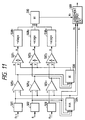
- Fig. 11 is a block diagram showing the arrangement of the entropy filter.
- a one-dimensional entropy filter is illustrated, which is easily extended to a two-dimensional form used in practice.
- Registers 501 to 503 for storing values f i-1 , f i , and f i+1 of three pixels centered on a target pixel defined as f i are arranged.
- Subtracters 5051 to 5053 are arranged at the outputs of the registers 501 to 503, respectively.
- a minimum value circuit 504 is arranged to receive the outputs from the registers 501 to 503.
- the minimum value circuit 504 outputs the minimum one of the values f i-1 , f i , and f k+1 .
- the outputs from the registers 501 to 503 are input to the + terminals of the subtracters 5051 to 5053, respectively.
- An output from the minimum value circuit 504 is commonly input to the - terminals of the subtracters 5051 to 5053.
- the outputs of the subtracters 5051 to 5053 are connected to the dividend input terminals of dividers 5071 to 5073, respectively, and commonly to an adder 506.
- the adder 506 calculates the sum of the outputs from the subtracters 5051 to 5053.
- the output of the adder 506 is commonly connected to the divider input terminals of dividers 5071 to 5073.
- the outputs from the dividers 5071 to 5073 are input to logarithmic circuits 5081 to 5083, respectively.
- Each of the logarithmic circuits 5081 to 5083 receives an input x and outputs -x ⁇ log(x).
- the outputs of the logarithmic circuits 5081 to 5083 are connected to an adder 510 for calculating the sum of the outputs from the logarithmic circuits 5081 to 5083.
- a judgement output circuit 509 is arranged in this entropy filter.
- the output of the minimum value circuit 504 is connected to the x1 terminal, the output of the register 502 is connected to the x2 terminal, and the output of the adder 510 is connected to the x3 terminal.
- an output from the adder 510 becomes an entropy value ⁇ i near the pixel f i . If this entropy value ⁇ i is zero, the output value of the minimum value circuit is output from this entropy filter. If the value ⁇ i is not zero, the output, i.e., the pixel value f i from the register 502 is output from the entropy filter. As a result, only the impulse noise is removed.
- the entropy filter 501 (more specifically, the two-dimensional entropy filter) is used to update the value of each pixel in accordance with the entropy value.
- the updated image data is then subjected to recording bit extraction in circuits from an image information input unit 101 in Fig. 12.
- the image processing circuit of the third embodiment is applicable to the recording/reproducing apparatus shown in Fig. 4.
- a total curvature calculating means 102 and a mean curvature calculating unit 103 can be replaced with the computing means for numerator of total curvature and the calculating means for numerator of mean curvature described in the second embodiment.
Landscapes
- Physics & Mathematics (AREA)
- General Physics & Mathematics (AREA)
- Engineering & Computer Science (AREA)
- Theoretical Computer Science (AREA)
- Image Processing (AREA)
- Television Signal Processing For Recording (AREA)
- Closed-Circuit Television Systems (AREA)
- Facsimile Image Signal Circuits (AREA)
- Processing Or Creating Images (AREA)
Applications Claiming Priority (9)
| Application Number | Priority Date | Filing Date | Title |
|---|---|---|---|
| JP4697893 | 1993-03-08 | ||
| JP5046978A JP2960624B2 (ja) | 1993-03-08 | 1993-03-08 | 画像処理装置および記録再生装置 |
| JP46978/93 | 1993-03-08 | ||
| JP78186/93 | 1993-04-05 | ||
| JP5078186A JP3009805B2 (ja) | 1993-04-05 | 1993-04-05 | 記録再生装置 |
| JP7818693 | 1993-04-05 | ||
| JP159487/93 | 1993-06-29 | ||
| JP05159487A JP3078151B2 (ja) | 1993-06-29 | 1993-06-29 | 画像処理装置および記録再生装置 |
| JP15948793 | 1993-06-29 |
Publications (3)
| Publication Number | Publication Date |
|---|---|
| EP0615205A2 true EP0615205A2 (de) | 1994-09-14 |
| EP0615205A3 EP0615205A3 (de) | 1994-11-30 |
| EP0615205B1 EP0615205B1 (de) | 2003-06-04 |
Family
ID=27292835
Family Applications (1)
| Application Number | Title | Priority Date | Filing Date |
|---|---|---|---|
| EP94103519A Expired - Lifetime EP0615205B1 (de) | 1993-03-08 | 1994-03-08 | Bildverarbeitungsvorrichtung und Aufzeichnungs-/Wiedergabegerät |
Country Status (4)
| Country | Link |
|---|---|
| US (1) | US5502710A (de) |
| EP (1) | EP0615205B1 (de) |
| AT (1) | ATE242519T1 (de) |
| DE (1) | DE69432772D1 (de) |
Cited By (2)
| Publication number | Priority date | Publication date | Assignee | Title |
|---|---|---|---|---|
| GB2364461A (en) * | 2000-05-24 | 2002-01-23 | Hewlett Packard Co | Correcting defective pixels in an image |
| WO2002045021A1 (fr) * | 2000-12-01 | 2002-06-06 | Japan Science And Technology Corporation | Filtre d'entropie et procede d'extraction de surface utilisant ce filtre |
Families Citing this family (5)
| Publication number | Priority date | Publication date | Assignee | Title |
|---|---|---|---|---|
| JP4042563B2 (ja) * | 2002-12-27 | 2008-02-06 | セイコーエプソン株式会社 | 画像ノイズの低減 |
| FR2854788B1 (fr) * | 2003-05-13 | 2005-08-19 | Edgard Cornier | Dispositif pour la mise en place d'une prothese de suspension uterine pour le traitement des prolapsus uterins |
| KR100552698B1 (ko) * | 2003-11-24 | 2006-02-20 | 삼성전자주식회사 | 정보 저장 장치 및 그 정보 추종 방법 |
| JP2013258537A (ja) | 2012-06-12 | 2013-12-26 | Canon Inc | 撮像装置、及びその画像表示方法 |
| US12288668B2 (en) * | 2023-05-11 | 2025-04-29 | Applied Materials Israel Ltd. | Entropy based image processing for focused ion beam delayer-edge slices detection |
Family Cites Families (5)
| Publication number | Priority date | Publication date | Assignee | Title |
|---|---|---|---|---|
| US4603430A (en) * | 1984-09-21 | 1986-07-29 | Hughes Aircraft Company | Target discrimination utilizing median filters |
| JPH0642260B2 (ja) * | 1987-11-30 | 1994-06-01 | 株式会社日立製作所 | 2値化方式 |
| JP2744339B2 (ja) * | 1990-08-03 | 1998-04-28 | キヤノン株式会社 | 情報処理装置及び情報処理方法 |
| JP2761801B2 (ja) * | 1990-10-04 | 1998-06-04 | キヤノン株式会社 | 角度的位置関係検出方法及びこれを用いたエンコーダ |
| US5323003A (en) * | 1991-09-03 | 1994-06-21 | Canon Kabushiki Kaisha | Scanning probe microscope and method of observing sample by using such a microscope |
-
1994
- 1994-03-08 EP EP94103519A patent/EP0615205B1/de not_active Expired - Lifetime
- 1994-03-08 DE DE69432772T patent/DE69432772D1/de not_active Expired - Lifetime
- 1994-03-08 AT AT94103519T patent/ATE242519T1/de not_active IP Right Cessation
- 1994-03-08 US US08/207,064 patent/US5502710A/en not_active Expired - Fee Related
Cited By (5)
| Publication number | Priority date | Publication date | Assignee | Title |
|---|---|---|---|---|
| GB2364461A (en) * | 2000-05-24 | 2002-01-23 | Hewlett Packard Co | Correcting defective pixels in an image |
| US6724945B1 (en) | 2000-05-24 | 2004-04-20 | Hewlett-Packard Development Company, L.P. | Correcting defect pixels in a digital image |
| GB2364461B (en) * | 2000-05-24 | 2004-06-23 | Hewlett Packard Co | Correcting defect pixels in a digital image |
| WO2002045021A1 (fr) * | 2000-12-01 | 2002-06-06 | Japan Science And Technology Corporation | Filtre d'entropie et procede d'extraction de surface utilisant ce filtre |
| US7460702B2 (en) | 2000-12-01 | 2008-12-02 | Japan Science And Technology Corporation | Entropy filter, and area extracting method using the filter |
Also Published As
| Publication number | Publication date |
|---|---|
| ATE242519T1 (de) | 2003-06-15 |
| EP0615205B1 (de) | 2003-06-04 |
| EP0615205A3 (de) | 1994-11-30 |
| US5502710A (en) | 1996-03-26 |
| DE69432772D1 (de) | 2003-07-10 |
Similar Documents
| Publication | Publication Date | Title |
|---|---|---|
| USRE37203E1 (en) | Feedback control for scanning tunnel microscopes | |
| US4889988A (en) | Feedback control for scanning tunnel microscopes | |
| Helava | Digital correlation in photogrammetric instruments | |
| Sim et al. | Object matching algorithms using robust Hausdorff distance measures | |
| US7085418B2 (en) | Template matching method and image processing device | |
| Ulupinar et al. | Refining edges detected by a LoG operator | |
| EP0516380B1 (de) | Mikroverschiebungselement für ein Tunnelrastermikroskop | |
| US5502710A (en) | Recording bit extraction by calculating curvature of pixels in scanning probe microscope | |
| US5432771A (en) | Information recording/reproducing apparatus for performing recording/reproduction of information by using probe | |
| EP0095332B1 (de) | Positionsbestimmungsvorrichtung | |
| Fortier et al. | GCV and ML methods of determining parameters in image restoration by regularization: Fast computation in the spatial domain and experimental comparison | |
| US5481521A (en) | Information recording and reproducing apparatus utilizing a tunneling current or interatomic forces | |
| Crowley | A multiresolution representation for shape | |
| Hase et al. | Segmentation method of document images by two‐dimensional fourier transformation | |
| Gómez et al. | Probabilistic estimation of local scale | |
| JP2960624B2 (ja) | 画像処理装置および記録再生装置 | |
| Kuijper et al. | Calculations on critical points under gaussian blurring | |
| JP3009805B2 (ja) | 記録再生装置 | |
| JP3078151B2 (ja) | 画像処理装置および記録再生装置 | |
| EP1628299A2 (de) | Fehlererkennungsverfahren einer Sondenposition und Gerät in einem sondenbasierten Datenspeichersystem | |
| Liu et al. | Recovery of spatially varying acoustical properties via automated partial differential equation identification | |
| US6674607B2 (en) | Method and apparatus for determining high order polynomials for linearization of position signals | |
| JP3064399B2 (ja) | 走査型プローブ顕微鏡画像処理装置 | |
| JPS6280768A (ja) | ステレオ画像処理方法 | |
| JPH05190431A (ja) | 電子線描画装置 |
Legal Events
| Date | Code | Title | Description |
|---|---|---|---|
| PUAI | Public reference made under article 153(3) epc to a published international application that has entered the european phase |
Free format text: ORIGINAL CODE: 0009012 |
|
| AK | Designated contracting states |
Kind code of ref document: A2 Designated state(s): AT BE CH DE DK ES FR GB GR IE IT LI LU NL PT SE |
|
| PUAL | Search report despatched |
Free format text: ORIGINAL CODE: 0009013 |
|
| AK | Designated contracting states |
Kind code of ref document: A3 Designated state(s): AT BE CH DE DK ES FR GB GR IE IT LI LU NL PT SE |
|
| 17P | Request for examination filed |
Effective date: 19950529 |
|
| GRAG | Despatch of communication of intention to grant |
Free format text: ORIGINAL CODE: EPIDOS AGRA |
|
| RIC1 | Information provided on ipc code assigned before grant |
Free format text: 7G 06T 5/00 A |
|
| 17Q | First examination report despatched |
Effective date: 20020604 |
|
| GRAG | Despatch of communication of intention to grant |
Free format text: ORIGINAL CODE: EPIDOS AGRA |
|
| GRAH | Despatch of communication of intention to grant a patent |
Free format text: ORIGINAL CODE: EPIDOS IGRA |
|
| GRAH | Despatch of communication of intention to grant a patent |
Free format text: ORIGINAL CODE: EPIDOS IGRA |
|
| GRAA | (expected) grant |
Free format text: ORIGINAL CODE: 0009210 |
|
| AK | Designated contracting states |
Designated state(s): AT BE CH DE DK ES FR GB GR IE IT LI LU NL PT SE |
|
| PG25 | Lapsed in a contracting state [announced via postgrant information from national office to epo] |
Ref country code: NL Free format text: LAPSE BECAUSE OF FAILURE TO SUBMIT A TRANSLATION OF THE DESCRIPTION OR TO PAY THE FEE WITHIN THE PRESCRIBED TIME-LIMIT Effective date: 20030604 Ref country code: LI Free format text: LAPSE BECAUSE OF FAILURE TO SUBMIT A TRANSLATION OF THE DESCRIPTION OR TO PAY THE FEE WITHIN THE PRESCRIBED TIME-LIMIT Effective date: 20030604 Ref country code: IT Free format text: LAPSE BECAUSE OF FAILURE TO SUBMIT A TRANSLATION OF THE DESCRIPTION OR TO PAY THE FEE WITHIN THE PRE;WARNING: LAPSES OF ITALIAN PATENTS WITH EFFECTIVE DATE BEFORE 2007 MAY HAVE OCCURRED AT ANY TIME BEFORE 2007. THE CORRECT EFFECTIVE DATE MAY BE DIFFERENT FROM THE ONE RECORDED.SCRIBED TIME-LIMIT Effective date: 20030604 Ref country code: FR Free format text: LAPSE BECAUSE OF FAILURE TO SUBMIT A TRANSLATION OF THE DESCRIPTION OR TO PAY THE FEE WITHIN THE PRESCRIBED TIME-LIMIT Effective date: 20030604 Ref country code: CH Free format text: LAPSE BECAUSE OF FAILURE TO SUBMIT A TRANSLATION OF THE DESCRIPTION OR TO PAY THE FEE WITHIN THE PRESCRIBED TIME-LIMIT Effective date: 20030604 Ref country code: BE Free format text: LAPSE BECAUSE OF FAILURE TO SUBMIT A TRANSLATION OF THE DESCRIPTION OR TO PAY THE FEE WITHIN THE PRESCRIBED TIME-LIMIT Effective date: 20030604 Ref country code: AT Free format text: LAPSE BECAUSE OF FAILURE TO SUBMIT A TRANSLATION OF THE DESCRIPTION OR TO PAY THE FEE WITHIN THE PRESCRIBED TIME-LIMIT Effective date: 20030604 |
|
| REG | Reference to a national code |
Ref country code: GB Ref legal event code: FG4D |
|
| REG | Reference to a national code |
Ref country code: CH Ref legal event code: EP |
|
| REG | Reference to a national code |
Ref country code: IE Ref legal event code: FG4D |
|
| REF | Corresponds to: |
Ref document number: 69432772 Country of ref document: DE Date of ref document: 20030710 Kind code of ref document: P |
|
| PG25 | Lapsed in a contracting state [announced via postgrant information from national office to epo] |
Ref country code: SE Free format text: LAPSE BECAUSE OF FAILURE TO SUBMIT A TRANSLATION OF THE DESCRIPTION OR TO PAY THE FEE WITHIN THE PRESCRIBED TIME-LIMIT Effective date: 20030904 Ref country code: PT Free format text: LAPSE BECAUSE OF FAILURE TO SUBMIT A TRANSLATION OF THE DESCRIPTION OR TO PAY THE FEE WITHIN THE PRESCRIBED TIME-LIMIT Effective date: 20030904 Ref country code: GR Free format text: LAPSE BECAUSE OF FAILURE TO SUBMIT A TRANSLATION OF THE DESCRIPTION OR TO PAY THE FEE WITHIN THE PRESCRIBED TIME-LIMIT Effective date: 20030904 Ref country code: DK Free format text: LAPSE BECAUSE OF FAILURE TO SUBMIT A TRANSLATION OF THE DESCRIPTION OR TO PAY THE FEE WITHIN THE PRESCRIBED TIME-LIMIT Effective date: 20030904 |
|
| PG25 | Lapsed in a contracting state [announced via postgrant information from national office to epo] |
Ref country code: DE Free format text: LAPSE BECAUSE OF FAILURE TO SUBMIT A TRANSLATION OF THE DESCRIPTION OR TO PAY THE FEE WITHIN THE PRESCRIBED TIME-LIMIT Effective date: 20030905 |
|
| PG25 | Lapsed in a contracting state [announced via postgrant information from national office to epo] |
Ref country code: ES Free format text: LAPSE BECAUSE OF FAILURE TO SUBMIT A TRANSLATION OF THE DESCRIPTION OR TO PAY THE FEE WITHIN THE PRESCRIBED TIME-LIMIT Effective date: 20030915 |
|
| NLV1 | Nl: lapsed or annulled due to failure to fulfill the requirements of art. 29p and 29m of the patents act | ||
| REG | Reference to a national code |
Ref country code: CH Ref legal event code: PL |
|
| PG25 | Lapsed in a contracting state [announced via postgrant information from national office to epo] |
Ref country code: LU Free format text: LAPSE BECAUSE OF NON-PAYMENT OF DUE FEES Effective date: 20040308 Ref country code: IE Free format text: LAPSE BECAUSE OF NON-PAYMENT OF DUE FEES Effective date: 20040308 |
|
| PLBE | No opposition filed within time limit |
Free format text: ORIGINAL CODE: 0009261 |
|
| STAA | Information on the status of an ep patent application or granted ep patent |
Free format text: STATUS: NO OPPOSITION FILED WITHIN TIME LIMIT |
|
| 26N | No opposition filed |
Effective date: 20040305 |
|
| EN | Fr: translation not filed | ||
| REG | Reference to a national code |
Ref country code: IE Ref legal event code: MM4A |
|
| PGFP | Annual fee paid to national office [announced via postgrant information from national office to epo] |
Ref country code: GB Payment date: 20050302 Year of fee payment: 12 |
|
| PG25 | Lapsed in a contracting state [announced via postgrant information from national office to epo] |
Ref country code: GB Free format text: LAPSE BECAUSE OF NON-PAYMENT OF DUE FEES Effective date: 20060308 |
|
| GBPC | Gb: european patent ceased through non-payment of renewal fee |
Effective date: 20060308 |