EP0615218A1 - Procédé et dispositif pour la compensation de l'humidité dans un détecteur à dispersion de lumière - Google Patents
Procédé et dispositif pour la compensation de l'humidité dans un détecteur à dispersion de lumière Download PDFInfo
- Publication number
- EP0615218A1 EP0615218A1 EP94103217A EP94103217A EP0615218A1 EP 0615218 A1 EP0615218 A1 EP 0615218A1 EP 94103217 A EP94103217 A EP 94103217A EP 94103217 A EP94103217 A EP 94103217A EP 0615218 A1 EP0615218 A1 EP 0615218A1
- Authority
- EP
- European Patent Office
- Prior art keywords
- light
- moisture
- transmitter
- receiver
- smoke density
- Prior art date
- Legal status (The legal status is an assumption and is not a legal conclusion. Google has not performed a legal analysis and makes no representation as to the accuracy of the status listed.)
- Granted
Links
Images
Classifications
-
- G—PHYSICS
- G08—SIGNALLING
- G08B—SIGNALLING SYSTEMS, e.g. PERSONAL CALLING SYSTEMS; ORDER TELEGRAPHS; ALARM SYSTEMS
- G08B29/00—Checking or monitoring of signalling or alarm systems; Prevention or correction of operating errors, e.g. preventing unauthorised operation
- G08B29/18—Prevention or correction of operating errors
- G08B29/20—Calibration, including self-calibrating arrangements
- G08B29/24—Self-calibration, e.g. compensating for environmental drift or ageing of components
-
- G—PHYSICS
- G08—SIGNALLING
- G08B—SIGNALLING SYSTEMS, e.g. PERSONAL CALLING SYSTEMS; ORDER TELEGRAPHS; ALARM SYSTEMS
- G08B17/00—Fire alarms; Alarms responsive to explosion
- G08B17/10—Actuation by presence of smoke or gases, e.g. automatic alarm devices for analysing flowing fluid materials by the use of optical means
- G08B17/103—Actuation by presence of smoke or gases, e.g. automatic alarm devices for analysing flowing fluid materials by the use of optical means using a light emitting and receiving device
- G08B17/107—Actuation by presence of smoke or gases, e.g. automatic alarm devices for analysing flowing fluid materials by the use of optical means using a light emitting and receiving device for detecting light-scattering due to smoke
-
- G—PHYSICS
- G08—SIGNALLING
- G08B—SIGNALLING SYSTEMS, e.g. PERSONAL CALLING SYSTEMS; ORDER TELEGRAPHS; ALARM SYSTEMS
- G08B17/00—Fire alarms; Alarms responsive to explosion
- G08B17/10—Actuation by presence of smoke or gases, e.g. automatic alarm devices for analysing flowing fluid materials by the use of optical means
- G08B17/11—Actuation by presence of smoke or gases, e.g. automatic alarm devices for analysing flowing fluid materials by the use of optical means using an ionisation chamber for detecting smoke or gas
- G08B17/113—Constructional details
Definitions
- the invention relates to a method for compensating the air humidity according to the preamble of claim 1 and to an apparatus for performing the method.
- the backward-scattering optical smoke detectors used today are excellent early warning devices for fires with smoke development, for example smoldering fires. When used in rooms with high air humidity, undesirable high false alarm rates often occur due to condensation in the optical detector.
- the backward scattering optical smoke detectors generally referred to as scattered light detectors, have very good smoke detection properties, they react disadvantageously to water vapor or small water droplets, because the scattered light detectors can detect the scattered light from water vapor that has penetrated into the measuring chamber, e.g. on the labyrinth, on ridges and lenses as condensation, do not differentiate from the scattered light caused by smoke.
- European patent application 0 418 410-A1 describes such a method and an apparatus therefor.
- the environmental parameter relative humidity with a in the measuring chamber Arranged moisture sensor measured and a measured moisture value determined therefrom by means of a linearizing device. Above a certain measured value for the relative air humidity, the smoke density measured value is compensated with the moisture measured value and the compensated smoke density measured value is further processed to form alarm criteria.
- the device provided for this purpose is designed such that the scattered light detector has a transmitter circuit which controls the light transmitter, a receiver circuit which converts the receiver current of the light receiver into a frequency change, an oscillator circuit which converts the measurement signals of the moisture sensor into frequency-analog signals, and has a microcomputer, which controls the transmitter circuit.
- the microcomputer measures the frequency change of the light receiver during a quartz-stable gate time and stores it as a smoke density measurement signal. Furthermore, he measures the frequency-analog signals of the moisture sensor and uses this to determine the value of the relative air humidity from a linearization table in the read-only memory and stores this as a moisture measurement value and compensates the smoke density measurement value with the moisture measurement value.
- the object of the invention is to further develop and improve the known method and the known device.
- the smoke density is measured with a scattered light detector based on the principle of optical backscattering.
- a generally pulse powered light transmitter e.g. an infrared light emitting semiconductor diode and a light receiver, e.g. a photodiode, are arranged in a labyrinth chamber so that only the light scattered by smoke particles that have penetrated into the measuring chamber falls on the light receiver.
- An electronic circuit amplifies the receiver current, which is further processed as a smoke density measurement.
- the air humidity is not determined with its own moisture sensor, but with the aid of a further light transmitter and the already existing light receiver.
- a moisture deposit on the receiving optics is detected by periodically measuring the smoke density with the first light sensor and, with a time offset, the moisture with the second light sensor and processing the two measured values in a downstream microcomputer.
- the moisture coating on the receiver lens reflects the light from the second light transmitter, which is arranged in the immediate vicinity of the light receiver in such a way that the emitted light touches the receiving optics approximately tangentially on its surface.
- the output signal of the light receiver for moisture detection depends on the thickness of the moisture film and is weakened accordingly if there is more moisture in the detector. This is evaluated in a manner known per se in the downstream microprocessor. It is expedient to set the received signal in the case of a dry scattered light detector via the control power of the second light transmitter so that an amplifier connected downstream of the light receiver operates in the upper modulation range.
- Every light transmitter is one Assigned transmission circuit, which is controlled by the microcomputer, the light receiver is followed by a receiving circuit in which the output signals of the light transmitter are amplified and then fed to the microcomputer, which digitizes the received signal and then processes it.
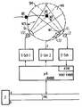
- a scattered light detector SM is indicated, which has an optical measuring chamber MK, a so-called labyrinth.
- the light emitted by the first light transmitter LS1 through the transmitter lens SL radiates in this measuring chamber MK. If smoke particles RP or water droplets WT enter the measuring chamber MK, the light from the light transmitter LS1 is scattered backwards and the light receiver LE with its receiving optics EL receives the scattered light.
- a second light transmitter LS2 is arranged in the immediate vicinity of the light receiver LE or the receiving optics EL so that the emitted radiation touches the lens surface approximately tangentially.
- the output signals of the light receiver LE are amplified via a receiver switch S-Sch, which is fed to the microcomputer ⁇ R, in which they are digitized using an analog-digital converter ADW.
- the microcomputer controls the two transmission circuits S-Sch1 and S-Sch2, which control the light transmitters LS1 and LS2 at different times.
- the microcomputer ⁇ R is connected to the primary signal line ML, which in turn is connected to a central Z via the a and b wires.
- the light receiver LE is generally a photodiode, which is once the light scattered by the smoke receives the first light-emitting diode LS and the other time receives the light from the second light-emitting diode (infrared semiconductor diode) LS2.
- the second infrared light-emitting semiconductor diode is arranged in the immediate vicinity of the receiving lens EL in such a way that the emitted radiation touches the lens surface approximately tangentially.
- the output voltage of the receiver circuit E-Sch is set via the drive power of the second infrared light-emitting diode LS2 with a dry surface of the receiving lens EL so that it comes into the upper modulation range of the receiving amplifier (E-Sch).
- Condensation ie a moisture coating on the surface of the receiving lens leads to a reflection of the infrared radiation of the second light-emitting diode LS2 on the surface of the water droplets WT sitting on the receiving lens EL, which leads to a reduction in the receiver output signal.
- the receiving lens can also be a lens-shaped surface of a light guide that directs the incident infrared radiation to the photodiode.
- the diode current of the second light-emitting diode is only a few percent of the diode current of the first light-emitting diode.
- the two light transmitters are operated at different times. Because of the low drive power and the special beam alignment of the second light transmitter, the resulting received signal is only dependent on the thickness of the moisture film on the surface of the receiving lens, but not on any smoke particles that may be present in the measuring chamber. In this case, the output signal of the light receiver is therefore a measured value for the air humidity.
- the microcomputer ⁇ R uses this to determine amplified and and digitized output signal the light receiver the degree of condensation via a linearization table in the read-only memory and stores it as the condensation value or the moisture value.
- the smoke density measurement value and the moisture measurement value can either be sent periodically to the fire control center Z via the connected primary signal line ML, so that the humidity compensation of the smoke density measurement value is carried out in the control center.
- the moisture compensation of the smoke density measured value can also take place in the scattered light detector itself, ie in the microcomputer of the scattered light detector.
- the microcomputer then sends the compensated smoke density measured value from the detector via the connected primary signal line to the fire alarm control panel.
- the regulation for humidity compensation takes into account the relationship between the humidity and the condensation described above and the uncompensated smoke detector measured value in such a way that the formation of water droplets is recognized and the resulting light reflection does not lead to an increase in the smoke detector measured value.
- the smoke density measured value is compensated and the compensated smoke density measured value is further processed for alarm generation. This ensures that the scattered light detector detects smoke particles that have penetrated even at high relative atmospheric humidity with an almost constant sensitivity and does not deliver any false alarms when condensation occurs.
Landscapes
- Physics & Mathematics (AREA)
- General Physics & Mathematics (AREA)
- Chemical & Material Sciences (AREA)
- Analytical Chemistry (AREA)
- Business, Economics & Management (AREA)
- Emergency Management (AREA)
- Engineering & Computer Science (AREA)
- Computer Security & Cryptography (AREA)
- Investigating Or Analysing Materials By Optical Means (AREA)
- Fire-Detection Mechanisms (AREA)
Applications Claiming Priority (2)
| Application Number | Priority Date | Filing Date | Title |
|---|---|---|---|
| DE4307585 | 1993-03-10 | ||
| DE4307585A DE4307585C1 (de) | 1993-03-10 | 1993-03-10 | Verfahren und Vorrichtung zur Kompensation der Feuchtigkeit in einem Streulichtmelder |
Publications (2)
| Publication Number | Publication Date |
|---|---|
| EP0615218A1 true EP0615218A1 (fr) | 1994-09-14 |
| EP0615218B1 EP0615218B1 (fr) | 1996-09-11 |
Family
ID=6482440
Family Applications (1)
| Application Number | Title | Priority Date | Filing Date |
|---|---|---|---|
| EP94103217A Expired - Lifetime EP0615218B1 (fr) | 1993-03-10 | 1994-03-03 | Procédé et dispositif pour la compensation de l'humidité dans un détecteur à dispersion de lumière |
Country Status (6)
| Country | Link |
|---|---|
| EP (1) | EP0615218B1 (fr) |
| AT (1) | ATE142807T1 (fr) |
| DE (2) | DE4307585C1 (fr) |
| DK (1) | DK0615218T3 (fr) |
| ES (1) | ES2091645T3 (fr) |
| GR (1) | GR3021486T3 (fr) |
Cited By (2)
| Publication number | Priority date | Publication date | Assignee | Title |
|---|---|---|---|---|
| EP1596349A1 (fr) * | 2004-05-13 | 2005-11-16 | Job Lizenz GmbH & Co. KG | Méthode pour la détection et l'annoncer de la condensation dans des détecteurs de fumée |
| WO2021155920A1 (fr) | 2020-02-05 | 2021-08-12 | Durag Gmbh | Dispositif de mesure de la lumière diffusée de particules dans un gaz |
Families Citing this family (5)
| Publication number | Priority date | Publication date | Assignee | Title |
|---|---|---|---|---|
| US5781291A (en) * | 1996-10-22 | 1998-07-14 | Pittway Corporation | Smoke detectors utilizing a hydrophilic substance |
| DE19912911C2 (de) * | 1999-03-22 | 2001-07-19 | Schako Metallwarenfabrik | Vorrichtung zur Erkennung von Rauch |
| DE102004020489B4 (de) * | 2004-04-26 | 2007-06-28 | Minimax Gmbh & Co. Kg | Brandmelder für Einsatz in Außenatmosphäre |
| DE102004032294B4 (de) * | 2004-07-03 | 2012-02-09 | Minimax Gmbh & Co. Kg | Beheizter Brandmelder |
| EP4280189A1 (fr) | 2022-05-18 | 2023-11-22 | Carrier Corporation | Surveillance de la condensation dans un système de détection de fumée aspirée |
Citations (2)
| Publication number | Priority date | Publication date | Assignee | Title |
|---|---|---|---|---|
| CH571750A5 (en) * | 1974-09-10 | 1976-01-15 | Nohmi Bosai Kogyo Co Ltd | Photoelectricccc aerosol or smoke detector - second photo cell receives reflected light from prism surface to compensate for contamination |
| EP0418410A1 (fr) * | 1989-09-19 | 1991-03-27 | Siemens Aktiengesellschaft | Méthode et appareil pour compenser l'humidité de l'air dans un détecteur de fumée |
-
1993
- 1993-03-10 DE DE4307585A patent/DE4307585C1/de not_active Expired - Fee Related
-
1994
- 1994-03-03 ES ES94103217T patent/ES2091645T3/es not_active Expired - Lifetime
- 1994-03-03 EP EP94103217A patent/EP0615218B1/fr not_active Expired - Lifetime
- 1994-03-03 DK DK94103217.9T patent/DK0615218T3/da active
- 1994-03-03 DE DE59400613T patent/DE59400613D1/de not_active Expired - Fee Related
- 1994-03-03 AT AT94103217T patent/ATE142807T1/de not_active IP Right Cessation
-
1996
- 1996-10-25 GR GR960402845T patent/GR3021486T3/el unknown
Patent Citations (2)
| Publication number | Priority date | Publication date | Assignee | Title |
|---|---|---|---|---|
| CH571750A5 (en) * | 1974-09-10 | 1976-01-15 | Nohmi Bosai Kogyo Co Ltd | Photoelectricccc aerosol or smoke detector - second photo cell receives reflected light from prism surface to compensate for contamination |
| EP0418410A1 (fr) * | 1989-09-19 | 1991-03-27 | Siemens Aktiengesellschaft | Méthode et appareil pour compenser l'humidité de l'air dans un détecteur de fumée |
Cited By (2)
| Publication number | Priority date | Publication date | Assignee | Title |
|---|---|---|---|---|
| EP1596349A1 (fr) * | 2004-05-13 | 2005-11-16 | Job Lizenz GmbH & Co. KG | Méthode pour la détection et l'annoncer de la condensation dans des détecteurs de fumée |
| WO2021155920A1 (fr) | 2020-02-05 | 2021-08-12 | Durag Gmbh | Dispositif de mesure de la lumière diffusée de particules dans un gaz |
Also Published As
| Publication number | Publication date |
|---|---|
| DK0615218T3 (da) | 1996-11-04 |
| ATE142807T1 (de) | 1996-09-15 |
| DE59400613D1 (de) | 1996-10-17 |
| DE4307585C1 (de) | 1994-03-10 |
| ES2091645T3 (es) | 1996-11-01 |
| EP0615218B1 (fr) | 1996-09-11 |
| GR3021486T3 (en) | 1997-01-31 |
Similar Documents
| Publication | Publication Date | Title |
|---|---|---|
| EP0360126B1 (fr) | Méthode d'opération d'un détecteur optique de fumée et détecteur de fumée pour la mise en oeuvre de la méthode | |
| EP2093734B1 (fr) | Détecteur de fumée doté d'une évaluation temporelle d'un signal de rétrodiffusion, procédé de test pour la capacité fonctionnelle d'un détecteur de fumée | |
| EP0418410B1 (fr) | Méthode et appareil pour compenser l'humidité de l'air dans un détecteur de fumée | |
| EP0530723A1 (fr) | Détecteur optique de fumée avec surveillance active | |
| DE4400363A1 (de) | Rauchmelder mit der Fähigkeit, sowohl Rauch als auch feine Partikel zu erkennen | |
| EP2541273A1 (fr) | Détection et détermination de distance d'objets | |
| WO2007085382A1 (fr) | Procédé de mesure du temps de propagation de la lumière | |
| EP0615218B1 (fr) | Procédé et dispositif pour la compensation de l'humidité dans un détecteur à dispersion de lumière | |
| EP1224641B2 (fr) | Dispositif de detection de fumee | |
| EP1783712B1 (fr) | Détecteur de feu optique fonctionnant par principe d'absorbance et diffusion combinée | |
| EP0418409B1 (fr) | Procédé et dispositif pour éviter les influences climatiques de l'environnement sur les indicateurs automatiques d'incendie | |
| DE19951557A1 (de) | Optoelektronische Vorrichtung | |
| DE3045217A1 (de) | Verfahren und vorrichtung zur optischen ueberwachung und sicherung von raeumen gegen eindringlinge | |
| DE3231025C2 (de) | Einrichtung zur Identifizierung von gepulster Laserstrahlung | |
| DE102017217280A1 (de) | Messeinrichtung zur Partikelmessung | |
| EP1596349B1 (fr) | Méthode pour la détection et l'annoncer de la condensation dans des détecteurs de fumée | |
| EP0596231B1 (fr) | Méthode et appareil pour mesurer la turbidité en milieu aqueux | |
| DE102010025929B4 (de) | Verfahren zum gepulsten Betreiben einer Lichtschranke und Lichtschranke | |
| DE29923142U1 (de) | Empfindlichkeitsregelung für Lichttaster | |
| DE19620642C2 (de) | Kantensensor | |
| DE202022103929U1 (de) | Optischer Sensor | |
| DE102006023971B4 (de) | Optischer Sensor und Verfahren zum Nachweis von Personen, Tieren oder Gegenständen | |
| EP0441771B1 (fr) | Procédé pour la détection de la présence de vapeur ou de fumée dans l'air d'échappement d'un appareil pour le chauffage de matériaux et dispositif pour exécuter ce procédé | |
| DE102021130058B4 (de) | Triangulationssensor und verfahren zum auswerten von mess-daten eines triangulationssensors | |
| EP1369836B1 (fr) | Détecteur d'incendie, et méthode d'opération |
Legal Events
| Date | Code | Title | Description |
|---|---|---|---|
| PUAI | Public reference made under article 153(3) epc to a published international application that has entered the european phase |
Free format text: ORIGINAL CODE: 0009012 |
|
| AK | Designated contracting states |
Kind code of ref document: A1 Designated state(s): AT BE CH DE DK ES FR GB GR IE IT LI LU NL PT |
|
| 17P | Request for examination filed |
Effective date: 19950207 |
|
| GRAG | Despatch of communication of intention to grant |
Free format text: ORIGINAL CODE: EPIDOS AGRA |
|
| GRAH | Despatch of communication of intention to grant a patent |
Free format text: ORIGINAL CODE: EPIDOS IGRA |
|
| 17Q | First examination report despatched |
Effective date: 19960214 |
|
| GRAH | Despatch of communication of intention to grant a patent |
Free format text: ORIGINAL CODE: EPIDOS IGRA |
|
| GRAA | (expected) grant |
Free format text: ORIGINAL CODE: 0009210 |
|
| AK | Designated contracting states |
Kind code of ref document: B1 Designated state(s): AT BE CH DE DK ES FR GB GR IE IT LI LU NL PT |
|
| REF | Corresponds to: |
Ref document number: 142807 Country of ref document: AT Date of ref document: 19960915 Kind code of ref document: T |
|
| REG | Reference to a national code |
Ref country code: CH Ref legal event code: NV Representative=s name: SIEMENS SCHWEIZ AG |
|
| REF | Corresponds to: |
Ref document number: 59400613 Country of ref document: DE Date of ref document: 19961017 |
|
| REG | Reference to a national code |
Ref country code: IE Ref legal event code: FG4D Free format text: 69809 |
|
| REG | Reference to a national code |
Ref country code: ES Ref legal event code: FG2A Ref document number: 2091645 Country of ref document: ES Kind code of ref document: T3 |
|
| REG | Reference to a national code |
Ref country code: DK Ref legal event code: T3 |
|
| ET | Fr: translation filed | ||
| ITF | It: translation for a ep patent filed | ||
| GBT | Gb: translation of ep patent filed (gb section 77(6)(a)/1977) |
Effective date: 19961114 |
|
| REG | Reference to a national code |
Ref country code: GR Ref legal event code: FG4A Free format text: 3021486 |
|
| SC4A | Pt: translation is available |
Free format text: 960923 AVAILABILITY OF NATIONAL TRANSLATION |
|
| PLBE | No opposition filed within time limit |
Free format text: ORIGINAL CODE: 0009261 |
|
| STAA | Information on the status of an ep patent application or granted ep patent |
Free format text: STATUS: NO OPPOSITION FILED WITHIN TIME LIMIT |
|
| 26N | No opposition filed | ||
| PGFP | Annual fee paid to national office [announced via postgrant information from national office to epo] |
Ref country code: IE Payment date: 19980212 Year of fee payment: 5 |
|
| PGFP | Annual fee paid to national office [announced via postgrant information from national office to epo] |
Ref country code: PT Payment date: 19980218 Year of fee payment: 5 |
|
| PGFP | Annual fee paid to national office [announced via postgrant information from national office to epo] |
Ref country code: GR Payment date: 19980227 Year of fee payment: 5 |
|
| PGFP | Annual fee paid to national office [announced via postgrant information from national office to epo] |
Ref country code: LU Payment date: 19980312 Year of fee payment: 5 |
|
| PGFP | Annual fee paid to national office [announced via postgrant information from national office to epo] |
Ref country code: DK Payment date: 19980330 Year of fee payment: 5 |
|
| PG25 | Lapsed in a contracting state [announced via postgrant information from national office to epo] |
Ref country code: LU Free format text: LAPSE BECAUSE OF NON-PAYMENT OF DUE FEES Effective date: 19990303 Ref country code: IE Free format text: LAPSE BECAUSE OF NON-PAYMENT OF DUE FEES Effective date: 19990303 |
|
| PG25 | Lapsed in a contracting state [announced via postgrant information from national office to epo] |
Ref country code: GR Free format text: LAPSE BECAUSE OF NON-PAYMENT OF DUE FEES Effective date: 19990331 Ref country code: DK Free format text: LAPSE BECAUSE OF NON-PAYMENT OF DUE FEES Effective date: 19990331 |
|
| PG25 | Lapsed in a contracting state [announced via postgrant information from national office to epo] |
Ref country code: PT Free format text: LAPSE BECAUSE OF NON-PAYMENT OF DUE FEES Effective date: 19990930 |
|
| REG | Reference to a national code |
Ref country code: PT Ref legal event code: MM4A Free format text: LAPSE DUE TO NON-PAYMENT OF FEES Effective date: 19990930 |
|
| REG | Reference to a national code |
Ref country code: DK Ref legal event code: EBP |
|
| PGFP | Annual fee paid to national office [announced via postgrant information from national office to epo] |
Ref country code: AT Payment date: 20010221 Year of fee payment: 8 |
|
| PGFP | Annual fee paid to national office [announced via postgrant information from national office to epo] |
Ref country code: GB Payment date: 20010309 Year of fee payment: 8 |
|
| PGFP | Annual fee paid to national office [announced via postgrant information from national office to epo] |
Ref country code: ES Payment date: 20010319 Year of fee payment: 8 |
|
| PGFP | Annual fee paid to national office [announced via postgrant information from national office to epo] |
Ref country code: BE Payment date: 20010320 Year of fee payment: 8 |
|
| PGFP | Annual fee paid to national office [announced via postgrant information from national office to epo] |
Ref country code: NL Payment date: 20010326 Year of fee payment: 8 |
|
| PGFP | Annual fee paid to national office [announced via postgrant information from national office to epo] |
Ref country code: FR Payment date: 20010327 Year of fee payment: 8 |
|
| PGFP | Annual fee paid to national office [announced via postgrant information from national office to epo] |
Ref country code: DE Payment date: 20010530 Year of fee payment: 8 |
|
| PGFP | Annual fee paid to national office [announced via postgrant information from national office to epo] |
Ref country code: CH Payment date: 20010614 Year of fee payment: 8 |
|
| REG | Reference to a national code |
Ref country code: GB Ref legal event code: IF02 |
|
| PG25 | Lapsed in a contracting state [announced via postgrant information from national office to epo] |
Ref country code: GB Free format text: LAPSE BECAUSE OF NON-PAYMENT OF DUE FEES Effective date: 20020303 Ref country code: AT Free format text: LAPSE BECAUSE OF NON-PAYMENT OF DUE FEES Effective date: 20020303 |
|
| PG25 | Lapsed in a contracting state [announced via postgrant information from national office to epo] |
Ref country code: ES Free format text: LAPSE BECAUSE OF NON-PAYMENT OF DUE FEES Effective date: 20020304 |
|
| PG25 | Lapsed in a contracting state [announced via postgrant information from national office to epo] |
Ref country code: LI Free format text: LAPSE BECAUSE OF NON-PAYMENT OF DUE FEES Effective date: 20020331 Ref country code: CH Free format text: LAPSE BECAUSE OF NON-PAYMENT OF DUE FEES Effective date: 20020331 Ref country code: BE Free format text: LAPSE BECAUSE OF NON-PAYMENT OF DUE FEES Effective date: 20020331 |
|
| BERE | Be: lapsed |
Owner name: *SIEMENS A.G. Effective date: 20020331 |
|
| PG25 | Lapsed in a contracting state [announced via postgrant information from national office to epo] |
Ref country code: NL Free format text: LAPSE BECAUSE OF NON-PAYMENT OF DUE FEES Effective date: 20021001 Ref country code: DE Free format text: LAPSE BECAUSE OF NON-PAYMENT OF DUE FEES Effective date: 20021001 |
|
| GBPC | Gb: european patent ceased through non-payment of renewal fee |
Effective date: 20020303 |
|
| REG | Reference to a national code |
Ref country code: CH Ref legal event code: PL |
|
| PG25 | Lapsed in a contracting state [announced via postgrant information from national office to epo] |
Ref country code: FR Free format text: LAPSE BECAUSE OF NON-PAYMENT OF DUE FEES Effective date: 20021129 |
|
| NLV4 | Nl: lapsed or anulled due to non-payment of the annual fee |
Effective date: 20021001 |
|
| REG | Reference to a national code |
Ref country code: FR Ref legal event code: ST |
|
| REG | Reference to a national code |
Ref country code: ES Ref legal event code: FD2A Effective date: 20030410 |
|
| PG25 | Lapsed in a contracting state [announced via postgrant information from national office to epo] |
Ref country code: IT Free format text: LAPSE BECAUSE OF NON-PAYMENT OF DUE FEES Effective date: 20050303 |