EP0615230A2 - Magnetbandgerät und Magnetkopfeinheit zum Gebrauch darin - Google Patents
Magnetbandgerät und Magnetkopfeinheit zum Gebrauch darin Download PDFInfo
- Publication number
- EP0615230A2 EP0615230A2 EP94200573A EP94200573A EP0615230A2 EP 0615230 A2 EP0615230 A2 EP 0615230A2 EP 94200573 A EP94200573 A EP 94200573A EP 94200573 A EP94200573 A EP 94200573A EP 0615230 A2 EP0615230 A2 EP 0615230A2
- Authority
- EP
- European Patent Office
- Prior art keywords
- magnetic
- spindle
- foil
- tape apparatus
- magnetic head
- Prior art date
- Legal status (The legal status is an assumption and is not a legal conclusion. Google has not performed a legal analysis and makes no representation as to the accuracy of the status listed.)
- Withdrawn
Links
Images

Classifications
-
- G—PHYSICS
- G11—INFORMATION STORAGE
- G11B—INFORMATION STORAGE BASED ON RELATIVE MOVEMENT BETWEEN RECORD CARRIER AND TRANSDUCER
- G11B5/00—Recording by magnetisation or demagnetisation of a record carrier; Reproducing by magnetic means; Record carriers therefor
- G11B5/48—Disposition or mounting of heads or head supports relative to record carriers ; arrangements of heads, e.g. for scanning the record carrier to increase the relative speed
- G11B5/54—Disposition or mounting of heads or head supports relative to record carriers ; arrangements of heads, e.g. for scanning the record carrier to increase the relative speed with provision for moving the head into or out of its operative position or across tracks
- G11B5/55—Track change, selection or acquisition by displacement of the head
- G11B5/5513—Specially adapted for transducing in both travelling directions of tape
- G11B5/5517—Controlled by automatic tape drive reversing arrangement
-
- G—PHYSICS
- G11—INFORMATION STORAGE
- G11B—INFORMATION STORAGE BASED ON RELATIVE MOVEMENT BETWEEN RECORD CARRIER AND TRANSDUCER
- G11B5/00—Recording by magnetisation or demagnetisation of a record carrier; Reproducing by magnetic means; Record carriers therefor
- G11B5/48—Disposition or mounting of heads or head supports relative to record carriers ; arrangements of heads, e.g. for scanning the record carrier to increase the relative speed
Definitions
- the invention relates to a magnetic-tape apparatus including a magnetic-head unit comprising a magnetic head rotatable between two positions, and a elongate foil wrapped partly around a spindle and provided with electrical conductor trace for the signal transmission between the magnetic head and a component of the magnetic-tape apparatus, which foil has a first end connected to the magnetic head and a second end to the component.
- a magnetic-tape apparatus of the type defined in the opening paragraph is commercially available as a Digital Compact Cassette (DCC) magnetic-tape apparatus.
- the known magnetic-tape apparatus has a magnetic head provided with transducing gaps for reading and writing information from/on a magnetic tape. Each of these transducing gaps is situated in a magnetic circuit with a transducing element. In operation the transducing elements are driven individually. In order to avoid a tangle of connection wires required for this purpose the connection wires take the form of electrical conductor tracks arranged on a foil.
- magnetic tape transport is possible in two opposite directions.
- the magnetic head may be rotatable through 180° between two extreme positions.
- the foil In order to allow a rotation through a angle of 180° the foil is coiled into a number of turns, the foil being wound up or unwound during rotation of the magnetic head.
- a disadvantage of the gown magnetic-tape apparatus is that in one of the extreme positions of the magnetic head, in which the foil has been unwound partly, the remaining coil of foil has a comparatively large diameter and consequently requires a substantial mounting space.
- the magnetic-tape apparatus in accordance with the invention is characterized in that a part of the foil between the two ends forms a loop situated at least for the greater part in a recess formed in the spindle, which recess extends over a part of the circumference of the spindle. Since the foil is not coiled but formed into a loop which extends in a recess in the spindle and is slackened in this recess when the magnetic head is rotated the foil occupies hardly any more space than the spindle itself, so that only a limited mounting space is needed.
- An embodiment of the magnetic-tape apparatus in accordance with the invention is characterized in that in the tangential direction the recess is bounded by two walls having such arcuate shapes viewed in a radial direction of the spindle that the loop lies against one of the arcuate walls in the extreme positions of the magnetic head.
- the loop is supported in the extreme positions of the magnetic head and is constrained to assume a such a shape that the foil remains substantially within the circumference of the spindle.
- An embodiment of the magnetic-tape apparatus in accordance with the invention is characterized in that the first end of the foil engages a slot formed in the spindle and extending through the central axis of the spindle. The first end by which the foil is fastened to the magnetic head is thus held in position and enclosed, so that the fastening is hardly loaded during rotation of the magnetic head.
- the invention also relates to a magnetic-head unit for use in the magnetic-tape apparatus in accordance with the invention and provided with a recess extending over a part of the circumference of the spindle to accommodate a foil with conductor tracks.
- An embodiment of the magnetic-head unit in accordance with the invention is characterized in that a part of the foil forms a loop situated in the recess formed in the spindle.
- FIG. 1 shows a magnetic-tape apparatus 1 in accordance with the invention.
- This magnetic-tape apparatus 1 is adapted to cooperate with a Digital Compact Cassette 3 (DCC) provided with magnetic tape.
- the magnetic-tape apparatus 1 has tape-transport means 5, 7 for the transport of magnetic tape in a longitudinal direction. These tape-transport means include capstans 9, 11 and pressure rollers 13, 15 which cooperate with one another.
- the magnetic-tape apparatus 1 comprises a magnetic-head unit 17.
- the magnetic-head unit 17 comprises a magnetic head 19 which is rotatable through 180° between two extreme positions.
- This magnetic-head unit further comprises a elongate foil 21 provided with electrical conductor tracks for the signal transmission between the rotatable magnetic head 19 and a component 23 situated in the magnetic-tape apparatus 1.
- This component 23 includes a amplifier for amplifying signals from and to the magnetic head 19.
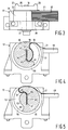
- Figures 2 and 3 show the magnetic-head unit 17 in a front view and a plan view, respectively.
- the magnetic head 19 is situated in a housing 25 having tape guides 27, 29, which guide the magnetic tape in a correct position relative to the magnetic head 19.
- the magnetic head 19 has, for example, nine write gaps and nine read gaps for, respectively, writing and reading information in digital form.
- the housing 25 with the magnetic head 19 is secured to a flange 35, said flange 33 being fixed to a spindle 35 in order to secure the magnetic head 19 to the spindle 35.
- the spindle 35 has a portion 37 of smaller diameter with which it is journalled in a bearing house 39 of the magnetic-head unit 17.
- the magnetic-head unit 17 has fixing means 41, 43 for securing the magnetic-head unit in the magnetic-tape apparatus.
- the foil 21, to which the magnetic head 19 is connected, carries electrical conductor tracks 45 for connection of the magnetic head 19 to the component 23 in the magnetic-tape apparatus.
- Figures 4 and 5 are sectional views of the magnetic-head unit 17, showing the magnetic head respectively in a first extreme position and in a second extreme position, rotated through 180° relative to this first extreme position.
- the foil 21 is wrapped partly around the spindle 35 and has a first end 47 connected to the magnetic head and has a second end 49 by which it can be connected to the component in the magnetic-tape apparatus.
- a part of the foil 21 between the two ends 47, 49 forms a loop 51, which is situated partly in a recess 53 formed in the spindle 35. This recess 53 extends over a part of the circumference 55 of the spindle 35.
- the recess is bounded by a bottom 57, which is substantially concentric with the circumference 55 of the spindle 35 and in the tangential direction it is bounded by two walls 59, 61 having a arcuate shape viewed in a radial direction of the spindle 35, the wall 59 being concave and the wall 61 being convex.
- the loop 51 lies against one of the arcuate walls 59 or 61.
- the first end 47 of the foil 21 engages in a slot 63 formed in the spindle 35 and extending through the central axis 65 of the spindle 35.
Landscapes
- Adjustment Of The Magnetic Head Position Track Following On Tapes (AREA)
Priority Applications (1)
| Application Number | Priority Date | Filing Date | Title |
|---|---|---|---|
| EP94200573A EP0615230A3 (de) | 1993-03-12 | 1994-03-07 | Magnetbandgerät und Magnetkopfeinheit zum Gebrauch darin. |
Applications Claiming Priority (3)
| Application Number | Priority Date | Filing Date | Title |
|---|---|---|---|
| EP93200728 | 1993-03-12 | ||
| EP93200728 | 1993-03-12 | ||
| EP94200573A EP0615230A3 (de) | 1993-03-12 | 1994-03-07 | Magnetbandgerät und Magnetkopfeinheit zum Gebrauch darin. |
Publications (2)
| Publication Number | Publication Date |
|---|---|
| EP0615230A2 true EP0615230A2 (de) | 1994-09-14 |
| EP0615230A3 EP0615230A3 (de) | 1995-04-05 |
Family
ID=26133698
Family Applications (1)
| Application Number | Title | Priority Date | Filing Date |
|---|---|---|---|
| EP94200573A Withdrawn EP0615230A3 (de) | 1993-03-12 | 1994-03-07 | Magnetbandgerät und Magnetkopfeinheit zum Gebrauch darin. |
Country Status (1)
| Country | Link |
|---|---|
| EP (1) | EP0615230A3 (de) |
Cited By (1)
| Publication number | Priority date | Publication date | Assignee | Title |
|---|---|---|---|---|
| US6394348B1 (en) * | 1999-12-13 | 2002-05-28 | Unisys Corporation | Apparatus for positioning magnetically coded substrate relative to a magnetic read head |
Family Cites Families (4)
| Publication number | Priority date | Publication date | Assignee | Title |
|---|---|---|---|---|
| US4945437A (en) * | 1987-09-11 | 1990-07-31 | Kabushiki Kaisha Sankyo Seiko Seisakusho | Magnetic head mechanism for reversing head orientation and moving head in tape width direction |
| JPH0542574Y2 (de) * | 1987-12-02 | 1993-10-27 | ||
| JP2876618B2 (ja) * | 1989-04-20 | 1999-03-31 | 松下電器産業株式会社 | テープレコーダの磁気ヘッド装置 |
| DE4122424A1 (de) * | 1991-07-06 | 1993-01-07 | Pierburg Gmbh | Gehaeuse mit drehbar angeordnetem elektrischen bauteil |
-
1994
- 1994-03-07 EP EP94200573A patent/EP0615230A3/de not_active Withdrawn
Cited By (1)
| Publication number | Priority date | Publication date | Assignee | Title |
|---|---|---|---|---|
| US6394348B1 (en) * | 1999-12-13 | 2002-05-28 | Unisys Corporation | Apparatus for positioning magnetically coded substrate relative to a magnetic read head |
Also Published As
| Publication number | Publication date |
|---|---|
| EP0615230A3 (de) | 1995-04-05 |
Similar Documents
| Publication | Publication Date | Title |
|---|---|---|
| US6188535B1 (en) | Arcuate scanning tape drive with a servo mechanism responsive to servo patterns in arcuate tracks on a moving tape | |
| KR0128209B1 (ko) | 회전자기헤드장치 | |
| US20010052543A1 (en) | Magnetic data cardreader system | |
| KR920020440A (ko) | 기록 테이프 경로 및 테이프 구동장치 | |
| EP0003444B1 (de) | Verfahren und Apparat zur Aufzeichnung von Videosignalen | |
| EP0615230A2 (de) | Magnetbandgerät und Magnetkopfeinheit zum Gebrauch darin | |
| US4599666A (en) | Disk drive system apparatus band actuator | |
| EP0597707A2 (de) | Magnetbandaufnahme-/Wiedergabegerät | |
| JPH0334177A (ja) | 磁気テープカセット | |
| US4564157A (en) | Magnetic recording tape cassette | |
| KR960005117B1 (ko) | 회전 자기헤드 장치 | |
| US3289963A (en) | Tape cartridge | |
| JPH06301946A (ja) | 磁気テープ装置及び磁気ヘッドユニット | |
| US5724215A (en) | Rotary transformer arrangement for a magnetic tape system drum assembly | |
| JPS609970Y2 (ja) | ヘツド内蔵磁気記録用カセツト | |
| KR19980081735A (ko) | 회전 자기 헤드 장치 | |
| JP4222269B2 (ja) | ヘッドシールド及び回転ヘッド装置 | |
| KR100513862B1 (ko) | 자기 기록/재생장치의 릴커버 | |
| US6724557B2 (en) | Magnetic recording apparatus and magnetic recording method | |
| JP3726354B2 (ja) | 磁気ディスク装置 | |
| JPH03286452A (ja) | ドラム装置 | |
| EP0350107A1 (de) | Schrägspurmagnetbandgerät mit einem Bandlauf mit Torsionsstrecken zur Korrektur dieses Bandlaufes | |
| JPS6267702A (ja) | 磁気記録再生装置のテ−プガイドドラム | |
| JPH04181503A (ja) | 回転ヘッドドラムテープ案内装置 | |
| JPH0214456A (ja) | 磁気記録再生装置 |
Legal Events
| Date | Code | Title | Description |
|---|---|---|---|
| PUAI | Public reference made under article 153(3) epc to a published international application that has entered the european phase |
Free format text: ORIGINAL CODE: 0009012 |
|
| AK | Designated contracting states |
Kind code of ref document: A2 Designated state(s): DE FR GB IT |
|
| PUAL | Search report despatched |
Free format text: ORIGINAL CODE: 0009013 |
|
| AK | Designated contracting states |
Kind code of ref document: A3 Designated state(s): DE FR GB IT |
|
| 17P | Request for examination filed |
Effective date: 19951005 |
|
| 17Q | First examination report despatched |
Effective date: 19970618 |
|
| RAP3 | Party data changed (applicant data changed or rights of an application transferred) |
Owner name: KONINKLIJKE PHILIPS ELECTRONICS N.V. |
|
| STAA | Information on the status of an ep patent application or granted ep patent |
Free format text: STATUS: THE APPLICATION IS DEEMED TO BE WITHDRAWN |
|
| 18D | Application deemed to be withdrawn |
Effective date: 19981001 |