EP0615312A2 - Elektrischer Steckverbinder - Google Patents
Elektrischer Steckverbinder Download PDFInfo
- Publication number
- EP0615312A2 EP0615312A2 EP94301638A EP94301638A EP0615312A2 EP 0615312 A2 EP0615312 A2 EP 0615312A2 EP 94301638 A EP94301638 A EP 94301638A EP 94301638 A EP94301638 A EP 94301638A EP 0615312 A2 EP0615312 A2 EP 0615312A2
- Authority
- EP
- European Patent Office
- Prior art keywords
- lid plate
- hood
- connector
- terminal
- connector according
- Prior art date
- Legal status (The legal status is an assumption and is not a legal conclusion. Google has not performed a legal analysis and makes no representation as to the accuracy of the status listed.)
- Granted
Links
- 230000006835 compression Effects 0.000 claims abstract description 17
- 238000007906 compression Methods 0.000 claims abstract description 17
- 230000002093 peripheral effect Effects 0.000 claims description 12
- 239000002657 fibrous material Substances 0.000 claims description 11
- 230000008878 coupling Effects 0.000 abstract description 13
- 238000010168 coupling process Methods 0.000 abstract description 13
- 238000005859 coupling reaction Methods 0.000 abstract description 13
- 239000000126 substance Substances 0.000 abstract description 10
- 230000000694 effects Effects 0.000 abstract description 4
- 239000000428 dust Substances 0.000 abstract description 2
- 238000011109 contamination Methods 0.000 abstract 1
- XLYOFNOQVPJJNP-UHFFFAOYSA-N water Substances O XLYOFNOQVPJJNP-UHFFFAOYSA-N 0.000 abstract 1
- 238000009413 insulation Methods 0.000 description 17
- 230000013011 mating Effects 0.000 description 12
- 238000010276 construction Methods 0.000 description 7
- 239000000835 fiber Substances 0.000 description 4
- 230000002708 enhancing effect Effects 0.000 description 2
- 238000000034 method Methods 0.000 description 2
- 239000000853 adhesive Substances 0.000 description 1
- 230000001070 adhesive effect Effects 0.000 description 1
- 230000006866 deterioration Effects 0.000 description 1
- 238000004134 energy conservation Methods 0.000 description 1
Images


Classifications
-
- H—ELECTRICITY
- H01—ELECTRIC ELEMENTS
- H01R—ELECTRICALLY-CONDUCTIVE CONNECTIONS; STRUCTURAL ASSOCIATIONS OF A PLURALITY OF MUTUALLY-INSULATED ELECTRICAL CONNECTING ELEMENTS; COUPLING DEVICES; CURRENT COLLECTORS
- H01R13/00—Details of coupling devices of the kinds covered by groups H01R12/70 or H01R24/00 - H01R33/00
- H01R13/44—Means for preventing access to live contacts
- H01R13/447—Shutter or cover plate
- H01R13/453—Shutter or cover plate opened by engagement of counterpart
- H01R13/4538—Covers sliding or withdrawing in the direction of engagement
-
- H—ELECTRICITY
- H01—ELECTRIC ELEMENTS
- H01R—ELECTRICALLY-CONDUCTIVE CONNECTIONS; STRUCTURAL ASSOCIATIONS OF A PLURALITY OF MUTUALLY-INSULATED ELECTRICAL CONNECTING ELEMENTS; COUPLING DEVICES; CURRENT COLLECTORS
- H01R13/00—Details of coupling devices of the kinds covered by groups H01R12/70 or H01R24/00 - H01R33/00
- H01R13/46—Bases; Cases
- H01R13/52—Dustproof, splashproof, drip-proof, waterproof, or flameproof cases
- H01R13/5213—Covers
Definitions
- This invention relates to a connector in which electrical safety is enhanced and more particularly to a connector suitable for charging a storage battery in an electric automobile.
- a car side connector connected to a battery is secured to a car body while a charger side connector is connected to an end of a flexible cable drawn out of a charger.
- the car side connector has a plurality of male terminals exposed in its hood while the charger side connector has a plurality of female terminals disposed in its housing to receive the male terminals.
- the charger side connector is formed into a shape adapted to be received in the hood of the car side connector. When the charger side connector is inserted into the hood, the terminals are electrically coupled with each other.
- the male terminals are exposed in the hood, they may be accidentally touched thus causing electric shock or be contaminated with extraneous substances resulting in electrical failure.
- Japanese Utility Model Public Disclosure No. 4-124774 (1992) discloses a connector in which a lid is attached through a hinge to the hood of the connector so that the lid can close and release an opening in the hood.
- Japanese Patent Public Disclosure No. 4-209479 (1992) discloses a connector wherein an insulation plate is movably mounted in a hood, the insulation plate is provided with through holes through which male terminals pass, a female connector is coupled to a male connector while pushing the insulation plate, the female connector and the insulation plate are detached from the male connector with the female connector accompanying the insulation plate, the female connector is disengaged from the insulation plate and the insulation plate is maintained in its position when the insulation plate moves to the distal ends of the male terminals.
- the insulation plate In order to enhance electrical safety, the insulation plate must be disengaged from the male terminals and move to a position covering the male terminals. However, even if the insulation plate merely moves over the distal ends of the male terminals, the through holes shift from the male terminals when the insulation plate is detached from the male terminals. Under this condition, when a female connector is inserted into the male connector, the insulation plate abuts on the distal ends of the male terminals, thereby causing the female connector to be hardly inserted into the male connector.
- a first object of the present invention is to provide a connector to which a mating connector can be readily connected and by which electrical safety can be enhanced.
- a second object of the present invention is to provide a connector which can positively prevent any accidental touching of the terminals or entering of extraneous substances.
- a plurality of male terminals are provided on the interior of a hood adapted to receive a female connector having a plurality of female terminals.
- the connector comprises: a lid plate provided with a plurality of terminal-through holes through each of which said male terminal can pass and received in said hood movably in the inserting and detaching directions; means for biasing said lid plate to a protection position in which said lid plate covers an opening in said hood; means for constraining said lid from falling off said hood; and means for positioning said lid plate when it is disposed at the protection position in the hood so that said terminal-through holes confront male terminals.
- the lid plate When the mating connector is not inserted into the hood of the connector, the lid plate is maintained at the protection position by the biasing means and constraining means so that the lid plate covers the male terminals at the open end of the hood, thereby preventing the fingers or extraneous substances from contacting with the male terminals. Even if an external force is temporarily applied to the lid plate so that the lid plate is pushed into an inner part of the hood, the lid plate can be returned to the protection position by the biasing means to cover the male terminal.
- the mating connector when the mating connector is inserted into the hood, the mating connector pushes the lid plate into the inner part of the hood, the male terminals pass through the terminal-through holes in the lid plate, and the male terminals are connected to the mating terminals.
- the lid plate at the protection position is constrained from falling off and rotating in the hood by the positioning means, the male terminals are positively inserted into the terminal-through holes and the lid plate can be smoothly pushed into the inner part of the hood.
- the lid plate When the female connector is drawn out of the hood, the lid plate is automatically advanced to the protection position by the biasing means in connection with the movement of the female connector.
- the connector of the present invention further comprises a flexible member attached to the rear side of said lid plate for deformably covering said terminal-through hole.
- the lid plate When the mating connector is not inserted into the hood of the connector, the lid plate is maintained at the protection position by the biasing means and constraining means so that the lid plate covers the male terminals at the open end of the hood, thereby preventing the fingers or extraneous substances from contacting with the male terminals. Under this position, the male terminals pass through the terminal-through holes. However, since the terminal-through holes are closed by the resilient or deformable tongue pieces or members having many fibers, fine substances such as dusts can not enter into the interior of the hood through the holes.
- the mating connector when the mating connector is inserted into the hood, the mating connector pushes the lid plate into the inner part of the hood, the male terminals pass through the terminal-through holes in the lid plate, and the male terminals are connected to the mating terminals. At this time, since the terminal-through holes are closed by the resilient tongue pieces or deformable fibers, the male terminals can pass readily through the holes.
- the connector of the present invention since when the mating connector is not inserted into the hood, the male terminals are covered by the lid plate at the open end of the hood, it is possible to prevent the fingers or extraneous substances from entering into the interior of the hood through the holes and since the holes are closed by the tongue pieces or the fibers, fine substances such as dusts can not enter into the interior of the hood through the holes.
- FIGS. 1 through 21 First through five embodiments of a connector of the present invention will be explained below by referring to FIGS. 1 through 21.
- a first embodiment of a connector of the present invention will be described below.
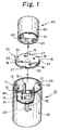
- a connector 10 comprises: a connector body 11 having a plurality of male terminals 12 which stand parallelly on a circular end face thereof; a cylindrical hood 13 surrounding the male terminals 12; a circular lid plate 15 disposed in the interior of the hood 13 so that the plate 15 can move in parallel with the male terminals 12; means 20 for biasing the lid plate 15 to an open end of the hood 13; means 25 for constraining the lid plate 15 from falling off the hood 13; and means 30 for positioning the lid plate 15 at a given position in a circumferential direction in the hood 13.
- the lid plate 15 has an outer diameter suitable for inserting into the hood 13 with a little clearance therebetween.
- the lid plate 15 is provided with terminal-through holes 16 through which the male terminal 12 passes freely.
- the biasing means 20 includes a compression coil spring 22 which is accommodated in a hole 21 in the center of an end face of the connector body 11 and a spring pusher 23 projected from an inner face of the lid plate 15.
- the spring pusher 23 is inserted into the hole 21 to compress the spring 22.
- the lid plate 15 is biased to an open end of the hood 13 by an elastic force exerted in the spring 22.
- the hood 13 is provided on the inner periphery adjacent to the open end with two limit projections 26.
- the lid plate 15 is provide on a peripheral edge with two recesses 27 corresponding to the limit projections 26. The lid plate 15 can enter into an inner part of the hood 13 when the recesses 27 are fitted to the projections 26 and the lid plate 15 is turned relatively to the hood 13 so that the recesses are shifted from the projections 26.
- the lid plate 15 received in the hood 13 is constrained from coming out of the hood 13 by engaging the outer peripheral edge with the limit projections 26 at a protection position near the open end of the hood 13 with the male terminals 12 passing through the terminal-through holes 16.
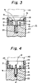
- the hood 13 is provided on the inner periphery with an elongated stop projection 31 extending in parallel to the male terminals 12 and shifted from the limit projections 26.
- the stop projection 31 is disposed at a position lower than the limit projections in the hood 13.
- a length of the stop projection 31 is longer than that of the male terminal 12 and there is a space with a distance equal to a thickness of the lid plate 15 between the limit projections 26 and a top end of the projection 31.
- the lid plate 15 is provided on a peripheral edge with a recess 32 corresponding to the stop projection 31 of the hood 13.
- the recess 32 is arranged in the lid plate 15 so that the recess 32 is shifted from the stop projection 31 when the recesses 27 in the lid plate 15 are fitted to the limit projections 26 of the hood 13.
- the lid plate 15 is also provided on the peripheral edge with an inner side stop projection 33 projecting downwardly adjacent to the recess 32 and with an outer side stop projection 34 projecting outwardly and shifted circumferentially from the projection 33.
- the lid plate 15 When the lid plate 15 is disposed at a protection position between the limit projections 26 and the stop projection 31 in a longitudinal direction of the male terminal 12 and the recess 32 is fitted to the stop projection 31, the inner and outer side stop projections 33 and 34 engage with the stop projection 31 and one of the limit projection 26, thereby constraining the lid plate 15 from rotating circumferentially with respect to the hood 13.
- the female connector 40 is electrically coupled to the connector 10 constructed above.
- the female connector 40 includes a circular female connector body 41 having an outer diameter enough to be closely fitted in the hood 13 and a female connector hood 42 adapted to be enclosed by the hood 13.
- the connector body 41 is provided with female terminals to be connected to the male terminals 12.
- the connector body 41 is also provided on its outer periphery with two escape grooves 43 to be fitted to the two limit projections 26 and with a stop groove 45 to be fitted to the stop projection 31.
- the connector body 41 is provided on the top end with an escape recess (not shown) to be fitted to the outer side stop projection on the lid plate 15.
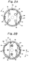
- the compression col spring 22 is accommodated in the spring-accommodating hole 21 of the connector body 11, the lid plate 15 is pushed into the hood 13 while elastically compressing the coil spring 22 by the spring pusher 23, as shown in FIG. 2A, with the opposite notches 27 being aligned with the stop projection 26 of the hood 13, and the inner edge of the lid plate 15 abuts on the limit projection 31.
- the recess 32 is aligned with the limit projection 31 of the hood 13 by rotating the lid plate 15 in the anticlockwise direction as shown by an arrow in FIG. 2B.
- the inner stop projection 33 of the lid plate 15 abuts on the side face of the limit projection 33.
- the outer stop projection 34 passes over one of the stop projections 26 and abuts on the side face of the stop projection 26, as shown in FIG. 2B.
- the lid plate 15 is constrained from being displaced out of the hood 13 in the protection position covering the male terminals 12 from the open end of the hood 13. If a force is applied to the lid plate 15 in a direction shown by an arrow a in FIG. 2B, the inner stop projection 33 of the lid plate 15 abuts on the limit projection 31 of the hood 13 to be constrained from rotating. Reversely, if a force is applied to the lid plate 15 in a direction shown by an arrow b in FIG. 2B, the outer stop projection 34 abuts on the stop projection 26 to be constrained from rotating. Accordingly, the lid plate 15 is prevented from rotating with the terminal-through hole 16 being aligned with the male terminal 12.
- lid plate 15 covers the male terminal 12 so as not to expose them in the connector 10, there is danger of the male terminals 12 being accidentally touched or of extraneous substances becoming attached to the male terminals 12.
- the female connector 40 may be merely inserted into the hood 13 with the grooves 43 and 45 being positioned opposite to the projections 34 and 26. Then, the female connector 40 advances in the hood 13 while the connector 40 compresses the compression coil spring 22 and pushes the lid plate 15 into the inner part of the hood 13. Finally, the female connector 40 reaches the coupling position shown in FIG. 4 to electrically interconnect the connectors.
- the lid plate 15 in the protection position is constrained from rotating and falling off by the stop projections 33 and 34 and the limit projections 31 and 26. Accordingly, even if the male terminals 12 extend completely through the terminal-through holes 16 in the lid plate 15 and then reenter them, the male terminals 12 can completely pass through them and the lid plate 15 is pushed into the inner part of the hood 13.
- the connector 40 Upon removing the connector 40 from the hood 13, the connector 40 is pulled out of the hood 13.
- the male terminals 12 are drawn out of the female terminals and the lid plate 15 moves to the open end of the hood 13 by the spring 22 while contacting with the end of the female connector 40.
- the lid plate 15 abuts on the limit projections 26 and maintains the protection position.
- a positioning means in the second embodiment of a connector 50 of the present invention includes a stop projection 53 provided on an inner periphery of a hood 52 and a recess 55 formed on a peripheral edge of a lid plate 54.
- the stop projection 53 extends from a bottom of the interior of the hood 52 to an open end of the hood 52.
- the recess 55 engages with the stop projection 53 to constrain the lid plate 54 from rotating in the hood 52 when the lid plate 54 is disposed at the protection position on the open end side above distal ends of male terminals 56 and at a lower position below the protection position.
- a constraining means includes two limit projections 58 provided on the inner periphery of the hood 52 and two resilient locking fingers 59 formed on the peripheral edge of the lid plate 54.
- the resilient locking fingers 59 are aligned with the limit projections 58 when the recess 55 engages with said stop projections 53.
- the lid plate 54 Upon assembling the connector 50 in the second embodiment, as shown in FIG. 6, the lid plate 54 is pushed into the hood 52 against the elastic force exerted in the spring 60 (biasing means) while the spring pusher 23 is compressing the spring 60, with the recess 54 being fitted to the stop projection 53. At this time, the slanted face of the resilient locking finger 59 rides and slides on the slanted face of the limit projection 58 so that the finger 59 is elastically deflected inwardly and moves to an inner part of the hood 52 more than the limit projections 58.
- FIG. 7 shows a coupling position of the connectors 40 and 50.
- FIGS. 8 to 10 A third embodiment of the connector will be explained below by referring to FIGS. 8 to 10.
- a lid plate 71 of a third embodiment of a connector 70 is provided on a peripheral edge with two resilient locking fingers 72 having an arcuate cross section and extending inwardly.
- the resilient locking finger 72 is provided on the outer face with a groove 74 extending in parallel with male terminals 73.
- the groove 74 has a stop shoulder 75 at its end.
- a connector body 76 of the connector 70 is provided with an arcuated groove 77 for receiving the resilient locking fingers 72 of the lid plate 71.
- a compression coil spring 73 constituting the biasing means is accommodated in the arcuated groove 77 in the connector body 76.
- the compression coil spring 78 pushes up the distal end of the resilient locking fingers 72 so that the lid plate 71 is biased to the protection position in the hood 79.
- a limit projection 80 is provided on the inner periphery of the arcuated groove 74.
- the limit projection 80 engages with the groove 74 in the resilient locking finger 72 to permit the lid plate 71 not to rotate circumferentially in the hood 79 but to move in the direction parallel to the male terminals 73.
- the limit projection 80 constrains the lid plate 71 from falling off the hood 79 when the stop shoulder 75 on the groove 74 in the resilient locking finger 72 abuts on the limit projection 80 (FIG. 9). That is, the resilient locking fingers 72 and limit projections 80 constitute the positioning means and constraining means.
- FIG. 10 shows a coupling position of the connectors 40 and 70.
- FIGS. 11 to 13 A fourth embodiment of the connector of the present invention will be explained below by referring to FIGS. 11 to 13.
- a lid plate 91 is provided with a cylindrical wall 93 extending downwardly.
- a resilient locking finger 92 is formed in the cylindrical wall 93.
- a connector body 94 of the connector 90 is provided on the entire periphery with an annular groove 95.
- a plurality of compression coil springs 96 constituting the biasing means are accommodated in the annular groove 95.
- the compression coil spring 96 pushes up the distal end of the cylindrical wall 93 to bias the lid plate 91 to the protection position (FIG. 12).
- the positioning means and constraining means comprise a groove 92 in a resilient locking finger 92, a stop shoulder 100, and a limit projection in an annular groove 95 in the same manner as those of the third embodiment (FIG. 12). Since the other constructions are the same as those of the first embodiment, a detailed explanation of them is omitted by giving the same signs to the elements and parts.
- FIG. 13 shows the connectors 40 and 90 connected with each other.
- the female connector 40 can be easily coupled to and detached from the connector in a single-handed operation.
- the male terminals 12 are covered by the lid plate 91, thereby enhancing electrical safety.
- FIGS. 14 to 21 A fifth embodiment of a connector of the present invention will be explained below by referring to FIGS. 14 to 21.
- This embodiment has the same basic construction as that of the first embodiment. Accordingly, different construction and operation between them are explained below. A detail explanation is omitted by giving the same signs to the same elements and parts.
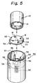
- a connector of the fifth embodiment further comprises a flexible member such as a dust-proofing rubber plate 150 attached to the rear side of the lid plate 15 for deformably covering the terminal-through hole 16.
- the dust-proofing rubber plate 150 made of a thin rubber sheet is attached to a rear side (lower side in the drawing) of the lid plate 15 by, for example, an adhesive.
- the dust-proofing rubber plate 150 has the same outer peripheral shape of the lid plate 15 and is provided at the center with an escape hole 151 for permitting the spring pusher 23 of the lid plate 15 to be passed through it.
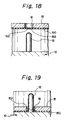
- the rubber plate 150 is provided with a plurality of tongue pieces 152 at the positions corresponding to the terminal-through holes 16.
- the tongue pieces 152 have many triangular pieces formed by slits extending radially from the center of the hole 16 to the peripheral edge.
- the tongue pieces 152 normally extend in a straight manner to close the holes 16, as shown in FIG. 18.
- the compression coil spring 22 is accommodated in the spring-accommodating hole 21 of the connector body 11, the lid plate 15 having the dust-proofing rubber plate 150 is pushed into the hood 13 while elastically compressing the coil spring 22 by the spring-pressing portion 23, as shown in FIG. 15A, with the opposite notches 27 being aligned with the stop projection 26 of the hood 13, and the inner edge of the lid plate 15 abuts on the limit projection 31.
- the recess 32 is fitted to the limit projection 31 of the hood 13 by rotating the lid plate 15 in the anticlockwise direction as shown by an arrow in FIG. 15B.
- the inner stop projection 33 of the lid plate 15 abuts on the side face of the limit projection 33.
- the outer stop projection 34 passes over one of the stop projections 26 and abuts on the side face of the stop projection 26, as shown in FIG. 2B.
- the lid plate 15 is constrained from displacing out of the hood 13 in the projection position covering the male terminals 12 from the open end of the hood 13. If a force is applied to the lid plate 15 in a direction shown by an arrow a in FIG. 15B, the inner stop projection 33 of the lid plate 15 abuts on the limit projection 31 of the hood 13 to be constrained from rotating. Reversely, if a force is applied to the lid plate 15 in a direction shown by an arrow b in FIG. 15B, the outer stop projection 34 abuts on the stop projection 26 to be constrained from rotating. Accordingly, the lid plate 15 is prevented from rotating with the terminal-through hole 16 being fitted to the male terminal 12.
- the lid plate 15 covers the male terminal 12 so as not to expose them in the connector 10, as shown in FIGS. 16 and 17, there is no danger of the male terminals 12 being accidentally touched or no problem of extraneous substances attached to the male terminals 12. Furthermore, since the terminal-through holes 16 are closed by the deformable tongue pieces 152 of the dust-proofing rubber plate 150, fine dusts or rain drops do not pass through the holes 16, thereby preventing electrical failure such as deterioration of an insulation function.
- the female connector 40 may be merely inserted into the hood 13 in the manner described above. Then, the female connector 40 advances in the hood 13 while the connector 40 compresses the compression coil spring 22 and pushes the lid plate 15 into the inner part of the hood 13. Finally, the female connector 40 reaches the coupling position shown in FIG. 17 to electrically interconnect the connectors.
- the lid plate 15 in the protection position is constrained from rotating and falling off by the stop projections 33 and 34 and the limit projections 31 and 26.
- the male terminals 12 can completely pass through them and the lid plate 15 is pushed into the inner part of the hood 13.
- the tongue pieces 152 of the dust-proofing rubber plate 150 which close the terminal-through holes 16 are elastically deformed to open the holes as shown in FIG. 19, thereby readily passing the male terminals 12 through the pieces 152.
- the connector 40 Upon removing the connector 40 from the hood 13, the connector 40 is pulled out of the hood 13.
- the male terminals 12 are drawn out of the female terminals and the lid plate 15 moves to the open end of the hood 13 by the spring 22 while contacting with the end of the female connector 40.
- the tongue pieces 152 of the dust-proofing rubber plate 150 return to the original position by their elasticity to close the terminal-through holes 16 as shown in FIG. 18 and the lid plate 15 abuts on the limit projections 26 and maintains the protection position.
- the female connector 40 it is possible to connect and detach the female connector 40 to and from the hood 13 by a simple operation in which the female connector 40 is held and inserted into and drawn out of the hood 13 by one hand.
- the male terminals are not exposed in the hood, electrical safety can be enhanced. Since the terminal-through holes 16 are always closed by the tongue pieces 152 of the dust-proofing rubber plate 150, it is possible to positively prevent dust, rain, or the like from entering through the terminal-through holes 16 into the hood 13.
Landscapes
- Connector Housings Or Holding Contact Members (AREA)
Applications Claiming Priority (4)
| Application Number | Priority Date | Filing Date | Title |
|---|---|---|---|
| JP7613493A JPH06267607A (ja) | 1993-03-09 | 1993-03-09 | コネクタ |
| JP76134/93 | 1993-03-09 | ||
| JP98556/93 | 1993-03-31 | ||
| JP9855693A JP2842143B2 (ja) | 1993-03-31 | 1993-03-31 | コネクタ |
Publications (3)
| Publication Number | Publication Date |
|---|---|
| EP0615312A2 true EP0615312A2 (de) | 1994-09-14 |
| EP0615312A3 EP0615312A3 (en) | 1996-01-24 |
| EP0615312B1 EP0615312B1 (de) | 1998-07-08 |
Family
ID=26417287
Family Applications (1)
| Application Number | Title | Priority Date | Filing Date |
|---|---|---|---|
| EP94301638A Expired - Lifetime EP0615312B1 (de) | 1993-03-09 | 1994-03-08 | Elektrischer Steckverbinder |
Country Status (3)
| Country | Link |
|---|---|
| US (1) | US5466164A (de) |
| EP (1) | EP0615312B1 (de) |
| DE (1) | DE69411420T2 (de) |
Cited By (16)
| Publication number | Priority date | Publication date | Assignee | Title |
|---|---|---|---|---|
| FR2786032A1 (fr) * | 1998-11-16 | 2000-05-19 | Delta Electronics Inc | Connecteur de surete |
| GB2362767B (en) * | 1999-02-03 | 2003-06-25 | Modular Connections Australia | Electrical coupler |
| EP1289074A3 (de) * | 2001-08-29 | 2004-04-14 | Harting Automotive GmbH & Co. KG | Buchse für eine schmutzgeschützte Steckverbindung sowie Steckverbindung |
| AT501257A1 (de) * | 2004-11-30 | 2006-07-15 | Damir Knezevic | Absenkbare abdeckung für steckdosen |
| DE19737157B4 (de) * | 1997-08-26 | 2006-10-05 | Jia-Sheng Lin | Multifunktioneller Mikrophonverbinder |
| WO2010015890A1 (en) * | 2008-08-04 | 2010-02-11 | Fci | Electrical connector assembly |
| EP2360794A1 (de) * | 2010-02-12 | 2011-08-24 | Ensto Finland Oy | Steckverbinder |
| US8192212B2 (en) | 2008-08-04 | 2012-06-05 | Fci Automotive Holding | Electrical connector system with temporarily blocking during unmating of two connectors |
| US8202112B2 (en) | 2008-07-28 | 2012-06-19 | Fci | Connector system and shorting member |
| DE102011100883A1 (de) * | 2011-05-07 | 2012-11-08 | Amphenol-Tuchel Electronics Gmbh | Elektrische Steckverbindung |
| WO2013046671A1 (en) * | 2011-09-27 | 2013-04-04 | Yazaki Corporation | Shielded connector |
| DE102014216711A1 (de) * | 2014-08-22 | 2016-03-10 | Bayerische Motoren Werke Aktiengesellschaft | Elektrisches Verbindersystem mit verbessertem Hochspannungsschutz |
| WO2018041660A1 (de) * | 2016-08-30 | 2018-03-08 | Dehn + Söhne Gmbh + Co. Kg | Elektrischer anschlussverbinder mit berührungsschutz |
| CN111326906A (zh) * | 2018-12-13 | 2020-06-23 | 大陆汽车有限公司 | 用于封闭壳体的前壁中的插入开口的封闭布置 |
| FR3095722A1 (fr) * | 2019-05-03 | 2020-11-06 | Psa Automobiles Sa | Dispositif de capotage de connecteur électrique pour habitacle de véhicule |
| CN115663516A (zh) * | 2021-07-07 | 2023-01-31 | 矢崎总业株式会社 | 连接器 |
Families Citing this family (52)
| Publication number | Priority date | Publication date | Assignee | Title |
|---|---|---|---|---|
| JPH0878096A (ja) * | 1994-08-31 | 1996-03-22 | Hosiden Corp | 多極コネクタ |
| US6072161A (en) * | 1996-08-06 | 2000-06-06 | Stein; Todd Anthony | Beverage container |
| US5733152A (en) * | 1996-10-09 | 1998-03-31 | Royal Die & Stamping Co., Inc. | Battery terminal adaptor and connector |
| US6102715A (en) | 1998-02-10 | 2000-08-15 | The Great American Gumball Corporation | Personal computer peripheral device adapter |
| US6139349A (en) * | 1998-07-24 | 2000-10-31 | Osram Sylvania Inc. | Electrical connector with tactile feedback |
| US6203356B1 (en) * | 1999-03-02 | 2001-03-20 | International Business Machines Corporation | Device and method for protecting pins of an electrical component |
| US7367121B1 (en) | 2000-01-05 | 2008-05-06 | Protectconnect | Electrical wiring method |
| US6979212B1 (en) * | 2000-01-14 | 2005-12-27 | Protect Connect | Safety electrical plug |
| US6224401B1 (en) * | 2000-01-27 | 2001-05-01 | Tsung-I Yu | Socket with safety device |
| US6315584B1 (en) | 2000-03-30 | 2001-11-13 | Hewlett-Packard Company | Protective cover for a printed circuit board electrical connector |
| US6604954B2 (en) * | 2001-10-23 | 2003-08-12 | Primax Electronics Ltd. | Power plug with safety feature |
| US6884111B2 (en) | 2002-05-23 | 2005-04-26 | Protectconnect | Safety module electrical distribution system |
| US6855008B1 (en) | 2003-10-06 | 2005-02-15 | Royal Die & Stamping Co., Inc. | Fuse holder with adjustable terminals |
| US7312396B1 (en) | 2004-03-13 | 2007-12-25 | Protectconnect, Inc. | Universal electrical wiring component |
| US6932650B1 (en) | 2004-03-25 | 2005-08-23 | Royal Die & Stamping Co., Inc. | Fused battery terminal connector |
| US20060003627A1 (en) * | 2004-07-01 | 2006-01-05 | Erik Freitag | Fused battery terminal connector |
| US20080053698A1 (en) | 2006-07-29 | 2008-03-06 | Steve Purves | Pre-wired power distribution system |
| CN101630788B (zh) * | 2008-07-18 | 2012-10-17 | 深圳富泰宏精密工业有限公司 | 插头 |
| JP5401972B2 (ja) * | 2008-12-18 | 2014-01-29 | ソニー株式会社 | プラグ、プラグ受け、および電力供給システム |
| TWI382604B (zh) * | 2009-02-18 | 2013-01-11 | Asustek Comp Inc | 連接器以及具有其之電子裝置 |
| JP4850266B2 (ja) * | 2009-03-19 | 2012-01-11 | 富士通株式会社 | コネクタ及びコネクタを有する装置 |
| FR2965119B1 (fr) * | 2010-09-22 | 2013-03-29 | Marechal Sepm | Connecteur electrique unipolaire a contacts en bout |
| EP2477281A1 (de) * | 2011-01-17 | 2012-07-18 | Jonas Brunvoll | Fassung |
| TWI514692B (zh) * | 2013-03-14 | 2015-12-21 | Hon Hai Prec Ind Co Ltd | 電源插座 |
| FR3017341B1 (fr) * | 2014-02-07 | 2016-02-26 | Peugeot Citroen Automobiles Sa | Dispositif de connexion a double usage pour le raccordement electrique d'un vehicule a un cordon de charge |
| JP6408780B2 (ja) * | 2014-04-08 | 2018-10-17 | 矢崎総業株式会社 | コネクタ嵌合構造 |
| US9647376B2 (en) * | 2014-06-20 | 2017-05-09 | Hubbell Incorporated | Tamper resistant receptacle |
| CN106159543A (zh) * | 2015-03-23 | 2016-11-23 | 联想(北京)有限公司 | 电子设备和电子充电系统 |
| US10285251B2 (en) * | 2015-07-29 | 2019-05-07 | Equivolt M Pte Ltd | Grounding device |
| JP6213583B2 (ja) * | 2016-01-27 | 2017-10-18 | 住友電装株式会社 | コネクタ |
| JP6210391B2 (ja) * | 2016-01-27 | 2017-10-11 | 住友電装株式会社 | コネクタ |
| US11256302B2 (en) * | 2016-02-03 | 2022-02-22 | Lenovo (Singapore) Pte. Ltd. | Magnetic hinge assemblies |
| EP3352308B1 (de) * | 2017-01-23 | 2020-11-04 | Berker GmbH & Co. KG | Vordere abdeckungsvorrichtung für steckdose und steckdose mit einem solchen vorderabdeckungsgerät ausgestattet |
| CN108365484A (zh) * | 2017-01-26 | 2018-08-03 | 廖生兴 | 自动式万用插座 |
| DE102017002705A1 (de) * | 2017-03-21 | 2018-09-27 | Abb Schweiz Ag | Schaltanlagenkontakteinrichtung |
| USD913955S1 (en) * | 2017-06-26 | 2021-03-23 | Marechal Electric | Connector |
| GB2564967B (en) * | 2017-06-28 | 2019-07-31 | Trojan Energy Ltd | Apparatus and system for connecting electric vehicles to an electrical network and method of use |
| US10008789B1 (en) | 2017-07-10 | 2018-06-26 | Royal Die & Stamping, Llc | Angled bolt T-bar battery terminal clamp |
| JP6990557B2 (ja) * | 2017-10-11 | 2022-01-12 | 株式会社オーディオテクニカ | マイクロホン用充電器 |
| CN108398119B (zh) * | 2018-01-26 | 2019-02-19 | 江苏中兴测绘信息有限公司 | 快速精准的测斜仪 |
| JP6897608B2 (ja) | 2018-03-07 | 2021-06-30 | 株式会社オートネットワーク技術研究所 | コネクタ及び電気接続装置 |
| CN108988002A (zh) * | 2018-07-10 | 2018-12-11 | 顺科新能源技术股份有限公司 | 一种充电插座用的机械自锁保护装置 |
| US11569607B2 (en) * | 2018-09-28 | 2023-01-31 | Foshan Shunde Midea Electrical Heating Appliances Manufacturing Co., Ltd. | Power coupler, ultrasonic oscillator device, ultrasonic oscillator, mounting assembly, cover body assembly, cooking utensil and heating apparatus |
| EP3873765A1 (de) * | 2018-10-31 | 2021-09-08 | Hirschmann Automotive GmbH | Vorrichtung und verfahren zum konduktiven laden |
| DE102019203193B4 (de) * | 2019-03-08 | 2022-10-06 | Volkswagen Aktiengesellschaft | Steckverbinderanordnung zum Verbinden und Trennen elektrischer Leitungen |
| US11203310B2 (en) * | 2019-12-20 | 2021-12-21 | Aptiv Technologies Limited | Electrical terminal stabilizer |
| CN111446578A (zh) * | 2020-05-14 | 2020-07-24 | 成都肯保捷旭阳新能源电器有限公司 | 一种具有高防护等级的充电枪模组结构 |
| CN212257767U (zh) * | 2020-05-19 | 2020-12-29 | 安徽大汉机器人集团有限公司 | 一种清洁工具的充电机构 |
| DE102022125817B3 (de) | 2022-10-06 | 2024-02-01 | Stark Spannsysteme Gmbh | Kupplung mit einem Kupplungsstück und einem Gegenkupplungsstück zur Herstellung einer lösbaren elektrischen Verbindung sowie Werkzeugmaschine mit einer solchen Kupplung |
| DE102023117202A1 (de) * | 2023-06-29 | 2025-01-02 | Kiekert Aktiengesellschaft | Ladesteckverbinder für Elektro- und Hybridfahrzeuge |
| US20250253556A1 (en) * | 2024-02-02 | 2025-08-07 | International Business Machines Corporation | Connector with integrated pin protection mechanism |
| CN120320105B (zh) * | 2025-06-18 | 2025-08-29 | 深圳市长江连接器有限公司 | 一种具有防护机构的电连接器 |
Family Cites Families (9)
| Publication number | Priority date | Publication date | Assignee | Title |
|---|---|---|---|---|
| US3519975A (en) * | 1968-03-25 | 1970-07-07 | Itt | Electrical connector |
| US3747047A (en) * | 1971-12-01 | 1973-07-17 | Hughes Aircraft Co | Latchable integrally molded electrical connector |
| US4109989A (en) * | 1975-06-10 | 1978-08-29 | Amp Incorporated | Environmentally sealed electrical connector |
| US4775327A (en) * | 1987-02-17 | 1988-10-04 | Amphenol Corporation | Connector with automatic protection cap |
| US5030119A (en) * | 1989-09-27 | 1991-07-09 | Safe Care Products, Inc. | Safety plug |
| JPH04124774A (ja) * | 1990-09-14 | 1992-04-24 | N T T Data Tsushin Kk | 関係データベースにおける階層構造のデータ蓄積方法 |
| JPH04136882A (ja) * | 1990-09-28 | 1992-05-11 | Canon Inc | シート幅検知機構及びこれを備えた画像形成装置 |
| JP2946000B2 (ja) * | 1990-12-06 | 1999-09-06 | 日本エー・エム・ピー株式会社 | 電気コネクタ |
| US5167516A (en) * | 1991-08-21 | 1992-12-01 | Foxconn International, Inc. | Connection with floating shield |
-
1994
- 1994-03-07 US US08/207,360 patent/US5466164A/en not_active Expired - Fee Related
- 1994-03-08 EP EP94301638A patent/EP0615312B1/de not_active Expired - Lifetime
- 1994-03-08 DE DE69411420T patent/DE69411420T2/de not_active Expired - Fee Related
Cited By (20)
| Publication number | Priority date | Publication date | Assignee | Title |
|---|---|---|---|---|
| DE19737157B4 (de) * | 1997-08-26 | 2006-10-05 | Jia-Sheng Lin | Multifunktioneller Mikrophonverbinder |
| FR2786032A1 (fr) * | 1998-11-16 | 2000-05-19 | Delta Electronics Inc | Connecteur de surete |
| GB2362767B (en) * | 1999-02-03 | 2003-06-25 | Modular Connections Australia | Electrical coupler |
| EP1289074A3 (de) * | 2001-08-29 | 2004-04-14 | Harting Automotive GmbH & Co. KG | Buchse für eine schmutzgeschützte Steckverbindung sowie Steckverbindung |
| AT501257A1 (de) * | 2004-11-30 | 2006-07-15 | Damir Knezevic | Absenkbare abdeckung für steckdosen |
| US8202112B2 (en) | 2008-07-28 | 2012-06-19 | Fci | Connector system and shorting member |
| WO2010015890A1 (en) * | 2008-08-04 | 2010-02-11 | Fci | Electrical connector assembly |
| US8192212B2 (en) | 2008-08-04 | 2012-06-05 | Fci Automotive Holding | Electrical connector system with temporarily blocking during unmating of two connectors |
| EP2360794A1 (de) * | 2010-02-12 | 2011-08-24 | Ensto Finland Oy | Steckverbinder |
| EP2523263A1 (de) * | 2011-05-07 | 2012-11-14 | Amphenol-tuchel Electronics GmbH | Elektrische Steckverbindung |
| DE102011100883A1 (de) * | 2011-05-07 | 2012-11-08 | Amphenol-Tuchel Electronics Gmbh | Elektrische Steckverbindung |
| DE102011100883B4 (de) * | 2011-05-07 | 2018-04-12 | Amphenol-Tuchel Electronics Gmbh | Stecker und elektrische Steckverbindung |
| WO2013046671A1 (en) * | 2011-09-27 | 2013-04-04 | Yazaki Corporation | Shielded connector |
| US9099808B2 (en) | 2011-09-27 | 2015-08-04 | Yazaki Corporation | Shielded connector |
| DE102014216711A1 (de) * | 2014-08-22 | 2016-03-10 | Bayerische Motoren Werke Aktiengesellschaft | Elektrisches Verbindersystem mit verbessertem Hochspannungsschutz |
| WO2018041660A1 (de) * | 2016-08-30 | 2018-03-08 | Dehn + Söhne Gmbh + Co. Kg | Elektrischer anschlussverbinder mit berührungsschutz |
| CN111326906A (zh) * | 2018-12-13 | 2020-06-23 | 大陆汽车有限公司 | 用于封闭壳体的前壁中的插入开口的封闭布置 |
| CN111326906B (zh) * | 2018-12-13 | 2021-08-17 | 大陆汽车有限公司 | 用于封闭壳体的前壁中的插入开口的封闭布置 |
| FR3095722A1 (fr) * | 2019-05-03 | 2020-11-06 | Psa Automobiles Sa | Dispositif de capotage de connecteur électrique pour habitacle de véhicule |
| CN115663516A (zh) * | 2021-07-07 | 2023-01-31 | 矢崎总业株式会社 | 连接器 |
Also Published As
| Publication number | Publication date |
|---|---|
| EP0615312A3 (en) | 1996-01-24 |
| DE69411420T2 (de) | 1998-11-19 |
| US5466164A (en) | 1995-11-14 |
| DE69411420D1 (de) | 1998-08-13 |
| EP0615312B1 (de) | 1998-07-08 |
Similar Documents
| Publication | Publication Date | Title |
|---|---|---|
| EP0615312B1 (de) | Elektrischer Steckverbinder | |
| US5314347A (en) | Latchable electrical connector system | |
| US5989052A (en) | Electrical outlet safety cover and cord connector | |
| EP0630074A2 (de) | Struktur eines Fahrzeugladeverbinders, Fahrzeugladeverbinder und Gehäuse zum Einschliessen des Verbinders | |
| EP1574886B1 (de) | Buchse mit Schutzblende für optischen Stecker | |
| CA2079252C (en) | Battery connector cover | |
| US5191172A (en) | Cable terminal protector | |
| EP0306635A2 (de) | Elektrischer Steckverbinder | |
| EP0622870A2 (de) | Elektrischer Verbinder mit vorgespannter Feder | |
| JPH0151031B2 (de) | ||
| JPH0613130A (ja) | 係止可能なケーシング半部を備えた電気的なプラグ結合装置 | |
| JP2000164295A (ja) | コネクタ | |
| JP3547034B2 (ja) | コネクタ嵌合方法及びそれに用いるコネクタ | |
| JPH06290826A (ja) | コネクタ | |
| CN112152013B (zh) | 电连接器和电连接器组件 | |
| US20090291602A1 (en) | Connection device to which electric device is connected and having dust-proof function | |
| JP7272032B2 (ja) | コネクタ | |
| KR20050098078A (ko) | 전기접속용 커넥터 | |
| CN221437741U (zh) | 用于车辆的充电端口开闭装置 | |
| CN220400975U (zh) | 防尘装置和用电设备 | |
| JP2700108B2 (ja) | コネクタの端子カバー構造 | |
| US11876320B2 (en) | Hinged seal cap | |
| CN216720352U (zh) | 一种两极插座保护结构和两极插座 | |
| CN211907807U (zh) | 防护盖和插座 | |
| CN210489953U (zh) | 一种带自动复位防尘盖的防水电连接器及其插接件 |
Legal Events
| Date | Code | Title | Description |
|---|---|---|---|
| PUAI | Public reference made under article 153(3) epc to a published international application that has entered the european phase |
Free format text: ORIGINAL CODE: 0009012 |
|
| 17P | Request for examination filed |
Effective date: 19940331 |
|
| AK | Designated contracting states |
Kind code of ref document: A2 Designated state(s): DE GB |
|
| PUAL | Search report despatched |
Free format text: ORIGINAL CODE: 0009013 |
|
| AK | Designated contracting states |
Kind code of ref document: A3 Designated state(s): DE GB |
|
| 17Q | First examination report despatched |
Effective date: 19961212 |
|
| GRAG | Despatch of communication of intention to grant |
Free format text: ORIGINAL CODE: EPIDOS AGRA |
|
| GRAG | Despatch of communication of intention to grant |
Free format text: ORIGINAL CODE: EPIDOS AGRA |
|
| GRAH | Despatch of communication of intention to grant a patent |
Free format text: ORIGINAL CODE: EPIDOS IGRA |
|
| GRAH | Despatch of communication of intention to grant a patent |
Free format text: ORIGINAL CODE: EPIDOS IGRA |
|
| GRAA | (expected) grant |
Free format text: ORIGINAL CODE: 0009210 |
|
| AK | Designated contracting states |
Kind code of ref document: B1 Designated state(s): DE GB |
|
| REF | Corresponds to: |
Ref document number: 69411420 Country of ref document: DE Date of ref document: 19980813 |
|
| PLBE | No opposition filed within time limit |
Free format text: ORIGINAL CODE: 0009261 |
|
| STAA | Information on the status of an ep patent application or granted ep patent |
Free format text: STATUS: NO OPPOSITION FILED WITHIN TIME LIMIT |
|
| 26N | No opposition filed | ||
| REG | Reference to a national code |
Ref country code: GB Ref legal event code: IF02 |
|
| PGFP | Annual fee paid to national office [announced via postgrant information from national office to epo] |
Ref country code: GB Payment date: 20020306 Year of fee payment: 9 |
|
| PGFP | Annual fee paid to national office [announced via postgrant information from national office to epo] |
Ref country code: DE Payment date: 20020320 Year of fee payment: 9 |
|
| PG25 | Lapsed in a contracting state [announced via postgrant information from national office to epo] |
Ref country code: GB Free format text: LAPSE BECAUSE OF NON-PAYMENT OF DUE FEES Effective date: 20030308 |
|
| PG25 | Lapsed in a contracting state [announced via postgrant information from national office to epo] |
Ref country code: DE Free format text: LAPSE BECAUSE OF NON-PAYMENT OF DUE FEES Effective date: 20031001 |
|
| GBPC | Gb: european patent ceased through non-payment of renewal fee |
Effective date: 20030308 |