EP0615321A2 - Dispositif ayant un laser à semi-conducteur stabilisé en longeur d'onde - Google Patents
Dispositif ayant un laser à semi-conducteur stabilisé en longeur d'onde Download PDFInfo
- Publication number
- EP0615321A2 EP0615321A2 EP94301489A EP94301489A EP0615321A2 EP 0615321 A2 EP0615321 A2 EP 0615321A2 EP 94301489 A EP94301489 A EP 94301489A EP 94301489 A EP94301489 A EP 94301489A EP 0615321 A2 EP0615321 A2 EP 0615321A2
- Authority
- EP
- European Patent Office
- Prior art keywords
- laser
- wavelength
- optical waveguide
- article
- optical fiber
- Prior art date
- Legal status (The legal status is an assumption and is not a legal conclusion. Google has not performed a legal analysis and makes no representation as to the accuracy of the status listed.)
- Granted
Links
Images
Classifications
-
- H—ELECTRICITY
- H01—ELECTRIC ELEMENTS
- H01S—DEVICES USING THE PROCESS OF LIGHT AMPLIFICATION BY STIMULATED EMISSION OF RADIATION [LASER] TO AMPLIFY OR GENERATE LIGHT; DEVICES USING STIMULATED EMISSION OF ELECTROMAGNETIC RADIATION IN WAVE RANGES OTHER THAN OPTICAL
- H01S5/00—Semiconductor lasers
- H01S5/06—Arrangements for controlling the laser output parameters, e.g. by operating on the active medium
- H01S5/068—Stabilisation of laser output parameters
- H01S5/0683—Stabilisation of laser output parameters by monitoring the optical output parameters
- H01S5/0687—Stabilising the frequency of the laser
-
- H—ELECTRICITY
- H01—ELECTRIC ELEMENTS
- H01S—DEVICES USING THE PROCESS OF LIGHT AMPLIFICATION BY STIMULATED EMISSION OF RADIATION [LASER] TO AMPLIFY OR GENERATE LIGHT; DEVICES USING STIMULATED EMISSION OF ELECTROMAGNETIC RADIATION IN WAVE RANGES OTHER THAN OPTICAL
- H01S5/00—Semiconductor lasers
- H01S5/02—Structural details or components not essential to laser action
- H01S5/024—Arrangements for thermal management
- H01S5/02407—Active cooling, e.g. the laser temperature is controlled by a thermo-electric cooler or water cooling
- H01S5/02415—Active cooling, e.g. the laser temperature is controlled by a thermo-electric cooler or water cooling by using a thermo-electric cooler [TEC], e.g. Peltier element
-
- H—ELECTRICITY
- H01—ELECTRIC ELEMENTS
- H01S—DEVICES USING THE PROCESS OF LIGHT AMPLIFICATION BY STIMULATED EMISSION OF RADIATION [LASER] TO AMPLIFY OR GENERATE LIGHT; DEVICES USING STIMULATED EMISSION OF ELECTROMAGNETIC RADIATION IN WAVE RANGES OTHER THAN OPTICAL
- H01S5/00—Semiconductor lasers
- H01S5/06—Arrangements for controlling the laser output parameters, e.g. by operating on the active medium
- H01S5/062—Arrangements for controlling the laser output parameters, e.g. by operating on the active medium by varying the potential of the electrodes
- H01S5/0625—Arrangements for controlling the laser output parameters, e.g. by operating on the active medium by varying the potential of the electrodes in multi-section lasers
- H01S5/06255—Controlling the frequency of the radiation
- H01S5/06256—Controlling the frequency of the radiation with DBR-structure
-
- H—ELECTRICITY
- H01—ELECTRIC ELEMENTS
- H01S—DEVICES USING THE PROCESS OF LIGHT AMPLIFICATION BY STIMULATED EMISSION OF RADIATION [LASER] TO AMPLIFY OR GENERATE LIGHT; DEVICES USING STIMULATED EMISSION OF ELECTROMAGNETIC RADIATION IN WAVE RANGES OTHER THAN OPTICAL
- H01S5/00—Semiconductor lasers
- H01S5/06—Arrangements for controlling the laser output parameters, e.g. by operating on the active medium
- H01S5/068—Stabilisation of laser output parameters
- H01S5/0683—Stabilisation of laser output parameters by monitoring the optical output parameters
- H01S5/06837—Stabilising otherwise than by an applied electric field or current, e.g. by controlling the temperature
Definitions
- This invention pertains to articles (e.g., wavelength division multiplexed optical fiber communication systems) that comprise a wavelength-stabilized laser radiation source.
- Wavelength division multiplexed (WDM) optical fiber communication systems are known. Such a system typically comprises wavelength reference means and feedback means that maintain the wavelength of the output radiation of a laser at a predetermined value.
- reference means comprise optical fiber with in-line refractive index grating.
- U.S. patent 5,077,816 discloses a wavelength multiplexed fiber communication system that comprises a narrow band (e.g., 60 GHz tuning range) semiconductor laser and a narrow band (e.g., 44 GHz) refractive index reflection grating, with the feedback loop locking the laser output to the center frequency of the grating.
- a narrow band e.g., 60 GHz tuning range
- a narrow band e.g., 44 GHz
- the scheme of the '816 patent involves use of a narrow band laser. However, it would frequently be desirable to be able to use lasers having a broad tuning range such that nominally identical (broad band) lasers could be used as sources in a WDM system, thus avoiding the need to use specially designed lasers for the various channels.
- the Giles et al. scheme typically does not provide access to all wavelengths within the tuning range of a (broad-band) laser. Such access typically would be desirable.
- the scheme of the '816 patent typically is not capable of start-up without human intervention (“cold-start") if the wavelength reference means (typically an in-line refractive index grating) does not have a single transmission minimum but exhibits also one or more subsidiary minima, as is frequently the case. It would clearly be desirable to have available a stabilization scheme that is capable of cold-start even under those circumstances. Finally, it would be desirable to have available a stabilization scheme that facilitates some choice in the control frequency, such that (typically unavoidable) small deviations from the target wavelength of the wavelength reference means can be readily compensated for.
- This application discloses an article that comprises a laser stabilization scheme that mitigates or eliminates at least some of the above recited shortcomings of the prior art schemes.
- the invention is as defined by the claims.
- the invention is embodied in an article (e.g., a WDM optical communication system) that comprises a semiconductor laser and control means for maintaining the wavelength of the (typically single mode) radiation output of the laser substantially at a predetermined value.
- the laser is a broad band laser (tuning range typically greater than 4 nm)
- the control means allow accessing of substantially all wavelengths within the tuning range of the laser, and the control means can facilitate cold-start of the laser.
- the article comprises a semiconductor laser (exemplarily a multi-segment distributed Bragg reflector (DBR) laser), means for causing a first current to flow through the laser such that the laser has a radiation output, and means for changing the wavelength of the output.
- the article further comprises first optical waveguide (e.g., optical fiber) means that are adapted for receiving the output, and still further comprises means for maintaining the wavelength of the output substantially equal to a desired wavelength.
- control means are connected to the means for changing the wavelength of the output and typically comprise second optical waveguide (e.g., also optical fiber) means that comprise an in-line refractive index grating and are connected to the first optical waveguide means such that a portion of the received radiation output is coupled from the first into the second waveguide means.
- the means for changing the output wavelength comprise means for causing a second electrical current to flow through the laser such that the wavelength of the laser output is a function of the second current, and further comprise means for changing the temperature of the laser.
- the article comprises means for providing an error signal that is the difference between a pre-selected reference signal (V ref ) and a signal that is proportional to the intensity of radiation transmitted through the in-line grating, means for varying the second current (I B ) until the error signal is equal to or below a preselected value, and means (exemplarily thermoelectric cooling means) for varying the temperature of the laser until the error signal is minimized.
- V ref a pre-selected reference signal
- I B second current
- thermoelectric cooling means for varying the temperature of the laser until the error signal is minimized.
- Preferred embodiments of the invention comprise a control element having a relatively wide (e.g., ⁇ 0.5 nm full width at half maximum) primary minimum.
- a relatively wide (e.g., ⁇ 0.5 nm full width at half maximum) primary minimum This offers several advantages over control schemes that require the use of an element having a very narrow primary minimum.
- the relatively wide minimum can be attained with a relatively short filter, making temperature control easier.
- the relatively wide minimum also facilitates compensation of (typically unavoidable) small departures from the center wavelength of the minimum.
- a broadly tunable laser it is easier to provide for cold-start capability if the width of the primary minimum is comparable to the wavelength step (exemplarily 1 nm in the below-described embodiment) per tuning step in I B .
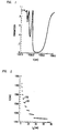
- FIG. 1 shows the transmission spectrum of a conventional in-line fiber refractive index grating, made conventionally by exposing a length of single mode optical fiber to a two-beam interference pattern. See, for instance, G. Meltz et al., Optics Letters , Vol. 14, p. 823.
- the Bragg band of the 2 mm long grating is centered at 1558.6 nm, with full-width-half-maximum of 1.3 nm.
- the grating has, in addition to the main lobe, several side lobes.
- a preferred embodiment comprises a multi-segment DBR laser of the type described in U. Koren et al., Applied Physics Letters , Vol. 58, p. 1239.
- a laser comprises two individually addressable segments, an "active" segment and a "Bragg" segment, with the output power of the laser being substantially determined by the current (I A ) through the former, and the wavelength of the output being a function of the current (I B ) through the latter.
- FIG. 2 shows the dependence of the wavelength on I B , for constant I A and temperature, in an exemplary multi-segment DBR laser.
- I B causes the laser to hop from mode to mode, with the gap between modes being 0.9 nm. Since the laser frequency varies by about 0.1 nm per °C temperature change, all wavelengths within the exemplary laser's tuning range can be reached by adjusting the laser temperature within a temperature range less than ⁇ 5°C.
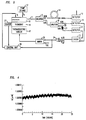
- FIG. 3 schematically depicts an exemplary article according to the invention, namely, a wavelength-stabilized optical fiber communication system.
- Multi-segment DBR laser 10 emits radiation 11 in response to current I A from pump source 12.
- the radiation is transmitted through a length of optical waveguide (typically a fiber) to conventional splitter 13 and divided in any desired ratio, e.g., 90%/10%, with one part (typically the larger one) transmitted through optical fiber 14 to detector 15.
- the laser is mounted on submount 16, exemplarily a block of copper, which in turn is attached to conventional thermoelectric cooling means 17.
- the second output of coupler 13 is fed to (optional) conventional splitter 18 and divided into two (typically equal) parts, with one of the parts detected by conventional detector means 19.
- the other part is coupled into optical fiber 20 with in-line grating 21, with the transmitted power detected by conventional detector 22.
- the electrical outputs of detectors 19 and 22 are provided to conventional divider 23, which normalizes the signal from detector 22 by dividing it by the signal from detector 19, which is directly proportional to the output intensity of laser 10.
- a back detector could provide an output that is proportional to the laser output intensity
- the output (A/B) of divider 23 is provided to the + input of operational amplifier 24, and a predetermined DC voltage V ref is provided to the - input.
- the output of the operational amplifier is proportional to (A/B) - V ref , as those skilled in the art will recognize.
- a DC current I DC is added to the output of 24, and the output current of 25 is provided to thermoelectric cooler 17.
- the output of 24 is also provided to control unit 26 (optionally comprising a conventional programmed microprocessor).
- control unit 26 optionally comprising a conventional programmed microprocessor.
- the functions performed by control unit 26 are relatively simple and could optionally be performed by a simple circuit, exemplarily comprising a conventional comparator.
- Control unit 26 provides current I B to laser 10, and optionally receives an input signal from temperature sensor 27.
- the desired wavelength of operation of laser 10 is 1559.08 nm, and that the available in-line grating has the spectrum of FIG. 1. It will be noted that the center wavelength of the spectrum is 1558.5 nm and thus does not correspond exactly to the desired wavelength.
- This condition is met at two wavelengths, at the target wavelength 1559.08 nm and at about 1558.16 nm. Means for discriminating between the two wavelengths can be readily provided, as is further discussed below.
- control loop operates such that it does not respond to the presence of subsidiary lobes in the spectrum of the control element.
- This can be readily accomplished by, e.g., ramping I B until signal A/B falls within a desired range of values, e.g., corresponds to T ⁇ 0.2, associated with wavelengths in the approximate range 1558.1-1559.2 nm.
- this control band is selected such that at least one mode of the laser falls within the band. In the exemplary case, modes 201 and 202 (see FIG. 2) fall, respectively, completely and partially within the range.
- Adder 25 provides to the thermoelectric cooler 17 a current that corresponds to the sum of an appropriately chosen current (I DC ) and the error signal, and the temperature of submount 16 (and thus of laser 10) is optionally monitored by temperature sensor 27.
- I DC is selected such that, for zero error signal, the temperature of the laser is in a convenient range, e.g., 15-25°C, and is optionally under control of unit 26.
- discrimination between desired and undesired lock-on wavelength could comprise determining the sign of the derivative of T with respect to Bragg current (I B ) or laser temperature.
- Electronic techniques for accomplishing this are well known. Exemplarily such techniques involve dithering the independent variable (e.g., I B ) around a set point, and measuring the resulting change in the dependent variable.
- Wavelength control means as shown in FIG. 3 were implemented as follows.
- the laser was a DBR laser as described in S. L. Woodward et al., IEEE Photonics Technology Letters , Vol. 4(5), p. 417.
- the laser output was directed onto a conventional microscope objective, then passed through an optical isolator and a second microscope objective which focused the beam into a (commercially available) 90%/10% fiber optic coupler.
- the 90% output of the coupler was provided to a wavelength meter (Advantest TQ 8325).
- the 10% output of the coupler was provided to a (commercially available) 50%/50% optical coupler.
- One of the outputs of the coupler was directed into a length of optical fiber with the, previously described, in-line refractive index grating therein.
- the optical power transmitted through the grating, as well as the optical power from the other output of the coupler, was each measured by means of a HP 8152A optical average power meter.
- Commercially available analog processors SRS 235
- SRS 235 were used as divider 23 and as "operational amplifier" 24.
- the signal from 24 was amplified using a conventional power supply/amplifier (HP 6817A), with an identical unit providing I DC .
- the control unit was a commercially available computer (AT&T 6386 with a National Instruments IEEE-488 instrumentation interface).
- the thermoelectric cooler also was conventional (Melcor CPl.4-11-06L). Currents I A and I B were provided by conventional DC power supplies (HP 6634A).
- the Bragg current was programmed to ramp from 0-75 mA in 1 mA steps, stopping once T was in the range 0 - 0.2.
- I B was 6 mA
- the temperature-control loop adjusted the laser temperature such that the error signal was minimized.
- the performance of the control loop was monitored for the next 25 hours.
- the results are shown in FIG. 4.
- the laser wavelength varied from 1559.072 to 1559.094 nm. The variations were found to be due to temperature variation of the in-line grating (22.7-24.1°C), and could be substantially eliminated by temperature stabilization of the reference element.
Landscapes
- Physics & Mathematics (AREA)
- Condensed Matter Physics & Semiconductors (AREA)
- General Physics & Mathematics (AREA)
- Electromagnetism (AREA)
- Optics & Photonics (AREA)
- Semiconductor Lasers (AREA)
- Optical Communication System (AREA)
Applications Claiming Priority (2)
| Application Number | Priority Date | Filing Date | Title |
|---|---|---|---|
| US28881 | 1993-03-10 | ||
| US08/028,881 US5299212A (en) | 1993-03-10 | 1993-03-10 | Article comprising a wavelength-stabilized semiconductor laser |
Publications (3)
| Publication Number | Publication Date |
|---|---|
| EP0615321A2 true EP0615321A2 (fr) | 1994-09-14 |
| EP0615321A3 EP0615321A3 (fr) | 1994-12-21 |
| EP0615321B1 EP0615321B1 (fr) | 1997-07-02 |
Family
ID=21846035
Family Applications (1)
| Application Number | Title | Priority Date | Filing Date |
|---|---|---|---|
| EP94301489A Expired - Lifetime EP0615321B1 (fr) | 1993-03-10 | 1994-03-02 | Dispositif ayant un laser à semi-conducteur stabilisé en longeur d'onde |
Country Status (4)
| Country | Link |
|---|---|
| US (1) | US5299212A (fr) |
| EP (1) | EP0615321B1 (fr) |
| JP (1) | JP3343166B2 (fr) |
| DE (1) | DE69403978T2 (fr) |
Cited By (11)
| Publication number | Priority date | Publication date | Assignee | Title |
|---|---|---|---|---|
| WO1997024786A1 (fr) * | 1995-12-29 | 1997-07-10 | Honeywell Inc. | Regulation de la longueur d'onde de sources de gyroscope a fibre optique |
| EP0854473A3 (fr) * | 1997-01-17 | 1999-03-17 | Matsushita Electric Industrial Co., Ltd. | Tête optique et appareil pour disque optique utilisant une telle tête |
| FR2785750A1 (fr) * | 1998-10-22 | 2000-05-12 | Samsung Electronics Co Ltd | Stabilisateur de longueur d'onde dans un systeme de transmission optique a multiplexage a division de longueur d'onde |
| WO2000052789A3 (fr) * | 1999-03-01 | 2001-01-11 | Univ California | Source laser accordable a surveillance integree de la longueur d'ondes, et mode de mise en oeuvre |
| EP0884866A4 (fr) * | 1996-03-13 | 2001-01-31 | Hitachi Ltd | Systeme de communication optique |
| WO2001009565A1 (fr) * | 1999-08-03 | 2001-02-08 | Korea Advanced Institute Of Science And Technology | Systeme de detection de contraintes dans une structure a fibres optiques |
| WO2001076028A1 (fr) * | 2000-04-05 | 2001-10-11 | Altitun Ab | Procede de stabilisation de la frequence et du mode d'un laser accordable |
| EP1309049A1 (fr) * | 2001-11-05 | 2003-05-07 | Agilent Technologies, Inc. (a Delaware corporation) | Dispositif sensible à la longueur d'onde pour système de stabilisation de longueur d'onde |
| EP1130718A3 (fr) * | 2000-01-20 | 2003-07-02 | Cyoptics (Israel) Ltd. | Laser stabilisé à fréquence accordable à réseau à fibre |
| EP1164367A3 (fr) * | 2000-06-16 | 2004-07-14 | Oki Electric Industry Co., Ltd. | Dispositif optique pour détecter la longueur d'onde et l'intensité de la lumière |
| GB2433644A (en) * | 2005-12-22 | 2007-06-27 | Bookham Technology Plc | A method of controlling a laser |
Families Citing this family (64)
| Publication number | Priority date | Publication date | Assignee | Title |
|---|---|---|---|---|
| US5691989A (en) * | 1991-07-26 | 1997-11-25 | Accuwave Corporation | Wavelength stabilized laser sources using feedback from volume holograms |
| JP2774914B2 (ja) * | 1993-04-02 | 1998-07-09 | 富士通株式会社 | レーザ点灯制御装置 |
| US5420877A (en) * | 1993-07-16 | 1995-05-30 | Cymer Laser Technologies | Temperature compensation method and apparatus for wave meters and tunable lasers controlled thereby |
| US6996150B1 (en) | 1994-09-14 | 2006-02-07 | Rohm Co., Ltd. | Semiconductor light emitting device and manufacturing method therefor |
| EP0703649B1 (fr) * | 1994-09-14 | 2003-01-15 | Matsushita Electric Industrial Co., Ltd. | Méthode de stabilisation de la puissance de sortie des harmoniques supérieurs et source laser à longueurs d'ondes courtes utilisant le même |
| JP2774955B2 (ja) * | 1994-11-01 | 1998-07-09 | 富士通株式会社 | 周囲光検出装置,光源点灯制御装置および読取装置 |
| US5706301A (en) * | 1995-08-16 | 1998-01-06 | Telefonaktiebolaget L M Ericsson | Laser wavelength control system |
| US5835650A (en) * | 1995-11-16 | 1998-11-10 | Matsushita Electric Industrial Co., Ltd. | Optical apparatus and method for producing the same |
| US5960259A (en) * | 1995-11-16 | 1999-09-28 | Matsushita Electric Industrial Co., Ltd. | Optical apparatus and method for producing the same |
| US6111681A (en) | 1996-02-23 | 2000-08-29 | Ciena Corporation | WDM optical communication systems with wavelength-stabilized optical selectors |
| US5943152A (en) * | 1996-02-23 | 1999-08-24 | Ciena Corporation | Laser wavelength control device |
| US5673129A (en) * | 1996-02-23 | 1997-09-30 | Ciena Corporation | WDM optical communication systems with wavelength stabilized optical selectors |
| DE59808542D1 (de) * | 1997-03-26 | 2003-07-03 | Infineon Technologies Ag | Lasermodul mit wellenlängenstabilisierung |
| US6188705B1 (en) | 1997-05-16 | 2001-02-13 | The United States Of America As Represented By The Administrator Of The National Aeronautics And Space Administration | Fiber grating coupled light source capable of tunable, single frequency operation |
| US6304350B1 (en) * | 1997-05-27 | 2001-10-16 | Lucent Technologies Inc | Temperature compensated multi-channel, wavelength-division-multiplexed passive optical network |
| US6115403A (en) * | 1997-07-22 | 2000-09-05 | Ciena Corporation | Directly modulated semiconductor laser having reduced chirp |
| US5875273A (en) * | 1997-07-22 | 1999-02-23 | Ciena Corporation | Laser wavelength control under direct modulation |
| IL121509A (en) * | 1997-08-11 | 2000-02-17 | Eci Telecom Ltd | Device and method for monitoring and controlling laser wavelength |
| IL121510A (en) * | 1997-08-11 | 2000-02-17 | Eci Telecom Ltd | Optical communications system |
| US6370290B1 (en) * | 1997-09-19 | 2002-04-09 | Uniphase Corporation | Integrated wavelength-select transmitter |
| JP4124845B2 (ja) * | 1997-10-24 | 2008-07-23 | 日本オプネクスト株式会社 | 光波長安定制御装置 |
| US6067181A (en) * | 1997-11-13 | 2000-05-23 | Ciena Corporation | Laser locking and self filtering device |
| US6125128A (en) * | 1997-11-13 | 2000-09-26 | Ciena Corporation | Laser output locking and self filtering device |
| US6058131A (en) * | 1997-11-17 | 2000-05-02 | E-Tek Dynamics, Inc. | Wavelength stabilization of laser source using fiber Bragg grating feedback |
| US6120190A (en) | 1997-11-26 | 2000-09-19 | Lasertron, Inc. | Spatially variable bandpass filter monitoring and feedback control of laser wavelength especially in wavelength division multiplexing communication systems |
| JPH11163462A (ja) * | 1997-11-27 | 1999-06-18 | Hitachi Ltd | 光波長安定制御装置、光送信器、光波長多重送信器 |
| US6289028B1 (en) | 1998-02-19 | 2001-09-11 | Uniphase Telecommunications Products, Inc. | Method and apparatus for monitoring and control of laser emission wavelength |
| US6134253A (en) * | 1998-02-19 | 2000-10-17 | Jds Uniphase Corporation | Method and apparatus for monitoring and control of laser emission wavelength |
| CA2228683C (fr) * | 1998-02-20 | 2002-05-14 | Ivan Avrutsky | Lasers accordables par wdm a reseau superpose |
| US6327064B1 (en) * | 1998-03-27 | 2001-12-04 | Ciena Corporation | Frequency stabilized and crosstalk-free signal sources for optical communication systems |
| US6282340B1 (en) * | 1998-04-23 | 2001-08-28 | The Furukawa Electric Co., Ltd. | Light wavelength tuning device and light source optical demultiplexer and wavelength division multiplexed optical communication system using the tuning device |
| US6353623B1 (en) * | 1999-01-04 | 2002-03-05 | Uniphase Telecommunications Products, Inc. | Temperature-corrected wavelength monitoring and control apparatus |
| US6560253B1 (en) | 1999-01-14 | 2003-05-06 | Jds Uniphase Corporation | Method and apparatus for monitoring and control of laser emission wavelength |
| US6449077B1 (en) * | 1999-03-09 | 2002-09-10 | Agere Systems Guardian Corp. | Method and apparatus for electrically switching a wavelength control system |
| US6545788B1 (en) * | 1999-03-09 | 2003-04-08 | Agere Systems, Inc. | Multiple path digital wavelength stabilization |
| US6369923B1 (en) * | 1999-09-07 | 2002-04-09 | Cinta Corporation | Multiwavelength stabilization with a single reference comb filter in DWDM systems |
| GB2360628A (en) * | 2000-03-25 | 2001-09-26 | Marconi Comm Ltd | A stabilised radiation source |
| US6587214B1 (en) | 2000-06-26 | 2003-07-01 | Jds Uniphase Corporation | Optical power and wavelength monitor |
| US6671296B2 (en) * | 2000-10-10 | 2003-12-30 | Spectrasensors, Inc. | Wavelength locker on optical bench and method of manufacture |
| US6611341B2 (en) | 2000-10-10 | 2003-08-26 | Spectrasensors, Inc. | Method and system for locking transmission wavelengths for lasers in a dense wavelength division multiplexer utilizing a tunable etalon |
| US6693928B2 (en) | 2000-10-10 | 2004-02-17 | Spectrasensors, Inc. | Technique for filtering chirp from optical signals |
| US6587484B1 (en) | 2000-10-10 | 2003-07-01 | Spectrasensor, Inc,. | Method and apparatus for determining transmission wavelengths for lasers in a dense wavelength division multiplexer |
| US6795459B2 (en) | 2000-10-18 | 2004-09-21 | Fibera, Inc. | Light frequency locker |
| US6486950B1 (en) | 2000-12-05 | 2002-11-26 | Jds Uniphase Corporation | Multi-channel wavelength monitor |
| US6993050B2 (en) | 2001-03-14 | 2006-01-31 | At&T Corp. | Transmit and receive system for cable data service |
| US6940889B2 (en) * | 2001-03-15 | 2005-09-06 | Lucent Technologies Inc. | Optical pulse source for long haul optical communication systems |
| JP3737383B2 (ja) * | 2001-05-21 | 2006-01-18 | ユーディナデバイス株式会社 | 半導体レーザモジュール試験装置および半導体レーザモジュール試験方法 |
| US6947458B2 (en) * | 2001-06-07 | 2005-09-20 | Alcatel Communications, Inc. | Power control circuit for laser diode having wavelength compensation |
| US6826210B2 (en) * | 2001-06-07 | 2004-11-30 | Alcatel Communications, Inc. | Power control circuit for laser diode having wavelength compensation |
| KR100424471B1 (ko) | 2001-06-23 | 2004-03-26 | 삼성전자주식회사 | 미세다공진기를 이용한 파장 고정 집적 광원 구조 |
| DE60229560D1 (de) * | 2002-04-30 | 2008-12-04 | Agilent Technologies Inc | Wellenlängenabstimmbarer laser mit parameter korrektur |
| US6876784B2 (en) * | 2002-05-30 | 2005-04-05 | Nanoopto Corporation | Optical polarization beam combiner/splitter |
| US7386205B2 (en) * | 2002-06-17 | 2008-06-10 | Jian Wang | Optical device and method for making same |
| US20040047039A1 (en) * | 2002-06-17 | 2004-03-11 | Jian Wang | Wide angle optical device and method for making same |
| US7283571B2 (en) * | 2002-06-17 | 2007-10-16 | Jian Wang | Method and system for performing wavelength locking of an optical transmission source |
| US6859303B2 (en) | 2002-06-18 | 2005-02-22 | Nanoopto Corporation | Optical components exhibiting enhanced functionality and method of making same |
| CN1692291A (zh) | 2002-08-01 | 2005-11-02 | 纳诺普托公司 | 精密相位延迟装置和其制造方法 |
| US7013064B2 (en) * | 2002-10-09 | 2006-03-14 | Nanoopto Corporation | Freespace tunable optoelectronic device and method |
| US6920272B2 (en) * | 2002-10-09 | 2005-07-19 | Nanoopto Corporation | Monolithic tunable lasers and reflectors |
| EP1597616A4 (fr) * | 2003-02-10 | 2008-04-09 | Nanoopto Corp | Polariseur large bande universel, dispositifs comprenant ledit polariseur et procede de fabrication dudit polariseur |
| US20040258355A1 (en) * | 2003-06-17 | 2004-12-23 | Jian Wang | Micro-structure induced birefringent waveguiding devices and methods of making same |
| CN100472900C (zh) * | 2006-03-31 | 2009-03-25 | 中兴通讯股份有限公司 | 一种用于可调谐激光器的波长控制电路 |
| US7941048B2 (en) * | 2007-06-29 | 2011-05-10 | Alcatel-Lucent Usa Inc. | Loss of signal detection |
| CN117157845A (zh) | 2021-03-24 | 2023-12-01 | 实光半导体科技(上海)有限公司 | 无模式跳变激光模块 |
Family Cites Families (9)
| Publication number | Priority date | Publication date | Assignee | Title |
|---|---|---|---|---|
| US4583228A (en) * | 1983-11-21 | 1986-04-15 | At&T Bell Laboratories | Frequency stabilization of lasers |
| JPH0663866B2 (ja) * | 1984-10-08 | 1994-08-22 | 日本電気株式会社 | 波長検出装置 |
| DE3885134D1 (de) * | 1987-03-30 | 1993-12-02 | Siemens Ag | Anordnung zur Steuerung oder Regelung einer Emissionswellenlänge und emittierten Leistung eines Halbleiterlasers. |
| JPS6418286A (en) * | 1987-07-13 | 1989-01-23 | Nec Corp | Semiconductor laser device |
| JPH01251681A (ja) * | 1988-03-25 | 1989-10-06 | Topcon Corp | 半導体レーザーの発振周波数・発振出力安定化装置 |
| GB2226127B (en) * | 1988-12-16 | 1992-07-29 | Stc Plc | Optical frequency monitor |
| US5077816A (en) * | 1989-12-26 | 1991-12-31 | United Technologies Corporation | Fiber embedded grating frequency standard optical communication devices |
| DE4039371C2 (de) * | 1990-12-10 | 2000-05-31 | Zeiss Carl Fa | Einrichtung zur Stabilisierung der Wellenlänge einer Laserdiode |
| US5208819A (en) * | 1992-01-23 | 1993-05-04 | General Instrument Corporation | Optical source with frequency locked to an in-fiber grating resonantor |
-
1993
- 1993-03-10 US US08/028,881 patent/US5299212A/en not_active Expired - Lifetime
-
1994
- 1994-03-02 DE DE69403978T patent/DE69403978T2/de not_active Expired - Lifetime
- 1994-03-02 EP EP94301489A patent/EP0615321B1/fr not_active Expired - Lifetime
- 1994-03-09 JP JP06434394A patent/JP3343166B2/ja not_active Expired - Lifetime
Cited By (16)
| Publication number | Priority date | Publication date | Assignee | Title |
|---|---|---|---|---|
| WO1997024786A1 (fr) * | 1995-12-29 | 1997-07-10 | Honeywell Inc. | Regulation de la longueur d'onde de sources de gyroscope a fibre optique |
| EP0884866A4 (fr) * | 1996-03-13 | 2001-01-31 | Hitachi Ltd | Systeme de communication optique |
| US6392979B1 (en) | 1997-01-17 | 2002-05-21 | Matsushita Electric Industrial Co., Ltd. | Optical pickup and optical disk apparatus using the same |
| EP1098300A1 (fr) * | 1997-01-17 | 2001-05-09 | Matsushita Electric Industrial Co., Ltd. | Tête de lecture optique et appareil de disque optique l'utilisant |
| EP0854473A3 (fr) * | 1997-01-17 | 1999-03-17 | Matsushita Electric Industrial Co., Ltd. | Tête optique et appareil pour disque optique utilisant une telle tête |
| CN1114203C (zh) * | 1997-01-17 | 2003-07-09 | 松下电器产业株式会社 | 光读取头及使用它的光盘装置 |
| FR2785750A1 (fr) * | 1998-10-22 | 2000-05-12 | Samsung Electronics Co Ltd | Stabilisateur de longueur d'onde dans un systeme de transmission optique a multiplexage a division de longueur d'onde |
| WO2000052789A3 (fr) * | 1999-03-01 | 2001-01-11 | Univ California | Source laser accordable a surveillance integree de la longueur d'ondes, et mode de mise en oeuvre |
| WO2001009565A1 (fr) * | 1999-08-03 | 2001-02-08 | Korea Advanced Institute Of Science And Technology | Systeme de detection de contraintes dans une structure a fibres optiques |
| EP1130718A3 (fr) * | 2000-01-20 | 2003-07-02 | Cyoptics (Israel) Ltd. | Laser stabilisé à fréquence accordable à réseau à fibre |
| WO2001076028A1 (fr) * | 2000-04-05 | 2001-10-11 | Altitun Ab | Procede de stabilisation de la frequence et du mode d'un laser accordable |
| US6888858B2 (en) | 2000-04-05 | 2005-05-03 | Adc Telecommunications, Inc. | Method for frequency and mode stabilization of a tuneable laser |
| EP1164367A3 (fr) * | 2000-06-16 | 2004-07-14 | Oki Electric Industry Co., Ltd. | Dispositif optique pour détecter la longueur d'onde et l'intensité de la lumière |
| EP1309049A1 (fr) * | 2001-11-05 | 2003-05-07 | Agilent Technologies, Inc. (a Delaware corporation) | Dispositif sensible à la longueur d'onde pour système de stabilisation de longueur d'onde |
| US6678293B2 (en) | 2001-11-05 | 2004-01-13 | Agilent Technologies, Inc. | Wavelength sensitive device for wavelength stabilization |
| GB2433644A (en) * | 2005-12-22 | 2007-06-27 | Bookham Technology Plc | A method of controlling a laser |
Also Published As
| Publication number | Publication date |
|---|---|
| DE69403978T2 (de) | 1997-10-16 |
| EP0615321B1 (fr) | 1997-07-02 |
| DE69403978D1 (de) | 1997-08-07 |
| JPH06350565A (ja) | 1994-12-22 |
| EP0615321A3 (fr) | 1994-12-21 |
| JP3343166B2 (ja) | 2002-11-11 |
| US5299212A (en) | 1994-03-29 |
Similar Documents
| Publication | Publication Date | Title |
|---|---|---|
| EP0615321B1 (fr) | Dispositif ayant un laser à semi-conducteur stabilisé en longeur d'onde | |
| EP0845166B1 (fr) | Systeme de regulation de longueur d'onde de laser | |
| US6928092B2 (en) | Method and apparatus for active numeric temperature compensation of an etalon in a wavelength stabilized laser | |
| KR101093661B1 (ko) | 외부공동 가변파장 레이저에서의 위상제어 | |
| US6353623B1 (en) | Temperature-corrected wavelength monitoring and control apparatus | |
| US6400737B1 (en) | Automatic closed-looped gain adjustment for a temperature tuned, wavelength stabilized laser source in a closed-loop feedback control system | |
| US6371662B1 (en) | Spatially variable filter laser wavelength monitoring/control | |
| EP1417740B1 (fr) | Appareil et procede de reglage de la longueur d'onde de fonctionnement d'un laser | |
| US6188705B1 (en) | Fiber grating coupled light source capable of tunable, single frequency operation | |
| US8619824B2 (en) | Low white frequency noise tunable semiconductor laser source | |
| US6359915B1 (en) | Wavelength-stabilized Bragg laser | |
| US5220578A (en) | Long term mode stabilization for distributed bragg reflector laser | |
| US7496119B2 (en) | External cavity laser with multiple stabilized modes | |
| JP2003507892A (ja) | ファイバ内周波数ロッカー | |
| US7130322B2 (en) | Wavelength tunable laser and method of controlling the same | |
| US6839364B1 (en) | Feedback control loop operating system for tunable source | |
| JP2003529224A (ja) | 安定化放射ソース | |
| US7356055B2 (en) | Method and device for regulating the average wavelength of a laser, especially a semiconductor laser | |
| CN1340231A (zh) | 锁定波长和监测可调谐激光器的模式的方法 | |
| US6327064B1 (en) | Frequency stabilized and crosstalk-free signal sources for optical communication systems | |
| JP3237499B2 (ja) | 周波数安定化光源 | |
| Ishii et al. | Wavelength stabilization of a superstructure-grating DBR laser for WDM networks | |
| DeCusatis et al. | Wavelength locked loops for optical communication networks | |
| KR20060067971A (ko) | 외부공동 가변파장 레이저에서의 위상제어 |
Legal Events
| Date | Code | Title | Description |
|---|---|---|---|
| PUAI | Public reference made under article 153(3) epc to a published international application that has entered the european phase |
Free format text: ORIGINAL CODE: 0009012 |
|
| AK | Designated contracting states |
Kind code of ref document: A2 Designated state(s): DE FR GB |
|
| PUAL | Search report despatched |
Free format text: ORIGINAL CODE: 0009013 |
|
| AK | Designated contracting states |
Kind code of ref document: A3 Designated state(s): DE FR GB |
|
| 17P | Request for examination filed |
Effective date: 19950608 |
|
| GRAG | Despatch of communication of intention to grant |
Free format text: ORIGINAL CODE: EPIDOS AGRA |
|
| GRAH | Despatch of communication of intention to grant a patent |
Free format text: ORIGINAL CODE: EPIDOS IGRA |
|
| 17Q | First examination report despatched |
Effective date: 19960722 |
|
| GRAH | Despatch of communication of intention to grant a patent |
Free format text: ORIGINAL CODE: EPIDOS IGRA |
|
| GRAA | (expected) grant |
Free format text: ORIGINAL CODE: 0009210 |
|
| AK | Designated contracting states |
Kind code of ref document: B1 Designated state(s): DE FR GB |
|
| REF | Corresponds to: |
Ref document number: 69403978 Country of ref document: DE Date of ref document: 19970807 |
|
| ET | Fr: translation filed | ||
| PLBE | No opposition filed within time limit |
Free format text: ORIGINAL CODE: 0009261 |
|
| STAA | Information on the status of an ep patent application or granted ep patent |
Free format text: STATUS: NO OPPOSITION FILED WITHIN TIME LIMIT |
|
| 26N | No opposition filed | ||
| PGFP | Annual fee paid to national office [announced via postgrant information from national office to epo] |
Ref country code: FR Payment date: 20010222 Year of fee payment: 8 |
|
| REG | Reference to a national code |
Ref country code: GB Ref legal event code: IF02 |
|
| PG25 | Lapsed in a contracting state [announced via postgrant information from national office to epo] |
Ref country code: FR Free format text: LAPSE BECAUSE OF NON-PAYMENT OF DUE FEES Effective date: 20021129 |
|
| REG | Reference to a national code |
Ref country code: FR Ref legal event code: ST |
|
| PGFP | Annual fee paid to national office [announced via postgrant information from national office to epo] |
Ref country code: GB Payment date: 20130228 Year of fee payment: 20 Ref country code: DE Payment date: 20130227 Year of fee payment: 20 |
|
| REG | Reference to a national code |
Ref country code: DE Ref legal event code: R071 Ref document number: 69403978 Country of ref document: DE |
|
| REG | Reference to a national code |
Ref country code: GB Ref legal event code: PE20 Expiry date: 20140301 |
|
| PG25 | Lapsed in a contracting state [announced via postgrant information from national office to epo] |
Ref country code: DE Free format text: LAPSE BECAUSE OF EXPIRATION OF PROTECTION Effective date: 20140304 Ref country code: GB Free format text: LAPSE BECAUSE OF EXPIRATION OF PROTECTION Effective date: 20140301 |