EP0615355A2 - Mobilstation und Zellwahlverfahren für Mobilkommunikation mit Kodemultiplexvielfachzugriff - Google Patents
Mobilstation und Zellwahlverfahren für Mobilkommunikation mit Kodemultiplexvielfachzugriff Download PDFInfo
- Publication number
- EP0615355A2 EP0615355A2 EP94103422A EP94103422A EP0615355A2 EP 0615355 A2 EP0615355 A2 EP 0615355A2 EP 94103422 A EP94103422 A EP 94103422A EP 94103422 A EP94103422 A EP 94103422A EP 0615355 A2 EP0615355 A2 EP 0615355A2
- Authority
- EP
- European Patent Office
- Prior art keywords
- level
- signal
- received
- window
- mobile station
- Prior art date
- Legal status (The legal status is an assumption and is not a legal conclusion. Google has not performed a legal analysis and makes no representation as to the accuracy of the status listed.)
- Granted
Links
Images


Classifications
-
- H—ELECTRICITY
- H04—ELECTRIC COMMUNICATION TECHNIQUE
- H04B—TRANSMISSION
- H04B7/00—Radio transmission systems, i.e. using radiation field
- H04B7/24—Radio transmission systems, i.e. using radiation field for communication between two or more posts
- H04B7/26—Radio transmission systems, i.e. using radiation field for communication between two or more posts at least one of which is mobile
- H04B7/2628—Radio transmission systems, i.e. using radiation field for communication between two or more posts at least one of which is mobile using code-division multiple access [CDMA] or spread spectrum multiple access [SSMA]
-
- H—ELECTRICITY
- H04—ELECTRIC COMMUNICATION TECHNIQUE
- H04W—WIRELESS COMMUNICATION NETWORKS
- H04W48/00—Access restriction; Network selection; Access point selection
- H04W48/20—Selecting an access point
Definitions
- the present invention relates to a mobile station or mobile terminal equipment of a CDMA (Code Division Multiplex Access) mobile communication system which transmits information spectrum-spread by a spreading code and uses a different spreading code to establish a different channel and, more particularly, to a visited cell selecting arrangement and a cell selecting method for the CDMA mobile communication system.
- CDMA Code Division Multiplex Access
- a base station optimum for communication changes every moment as the mobile station moves or travels. It is therefore necessary, in the mobile communication system, to properly select the base station optimum for communication (i.e. a base station belonging to the cell where the mobile station is currently located) each time the mobile station moves from a certain cell to the adjoining one. This is called a cell determination (or cell selection) and the system which performs communication through a base station selected by such a cell determination is referred to as a cellular system.
- the cellular system could be implemented using FDMA (Frequency Division Multiplex Access), TDMA (Time Division Multiplex) and CDMA (Code Division Multiplex Access) techniques.
- each cell is assigned a plurality of communication channels and at least one control channel.
- the cell selected as mentioned above is optimum or not has a great influence on the channel (or system) capacity, the channel quality and so forth. That is, in the event that a cell distant from the mobile station is selected erroneously, both the mobile station and the base station will transmit with power greater than needed when the optimum cell is selected. This increases interference with other stations, wherein the signal to interference signal ratio diminishes, resulting in the channel quality being degraded. Furthermore, the increase in interference causes a decrease in the number of mobile stations that are allowed to communicate simultaneously, and hence reduces the channel capacity.
- the base station of each cell always transmits via the control channel a paging message, the configuration of the control channel, base station identifying information, etc. to the mobile station. Being turned-on, the mobile station sequentially searches control channels listed in its storage corresponding to respective base stations and measures the signal receiving level in each control channel. The mobile station selects a control channel of the highest receiving level among those having receiving levels above a predetermined threshold value and determines that the base station corresponding to the control channel thus selected is an optimum base station (i.e. a base station nearest to the mobile station). The mobile station is set to the state for receiving the control channel of that base station, thus entering the wait state.
- the mobile station In the wait state, the mobile station periodically searches control channels of other cells and consequently other base stations in a sequential order and measures their receiving levels, because it is considered that the base station for optimum communication might change as the mobile station moves.
- the newly measured receiving level of each of the other control channels is compared with a value that is the sum of the receiving level of the currently-used control channel and a predetermined threshold value, and when the former is higher than the latter, it is determined that the mobile station has proceeded into a different cell, and the control channel for which the mobile station has been set to the wait state is switched accordingly.
- the mobile station transmits a call connect request signal to the base station of the cell thus selected.
- the mobile station periodically searches the other control channels and measures their receiving levels.
- the receiving level of each of the other control channels is compared with a value that is the sum of the receiving level of the current control channel and a predetermined threshold value, and when the former is higher than the latter, it is determined that the mobile station has proceeded into a different cell, and the communication channel is switched accordingly.
- each mobile station measures the receiving level of the control channel assigned to each cell and compares it with the abovementioned value to determine the cell in which the mobile station is currently located.
- a PN code sequence can be generated, for example, by EXCLUSIVE ORing the outputs from the last stage and a desired intermediate stage of a shift register composed of n delay stages, inputting the resulting exclusive OR into the first stage of the shift register and driving the shift register with a clock signal of a predetermined period T.
- a random code of a fixed pattern that repeats in a cycle of 2 n -1 bits (hereinafter called chips to distinguish from bits in information signal) at maximum is obtained depending on which of the intermediate stage outputs is chosen.
- chips to distinguish from bits in information signal) at maximum is obtained depending on which of the intermediate stage outputs is chosen.
- the mobile station multiplies (that is, despreads) the received signal by the spreading code corresponding to a desired channel while maintaining the phase relation that maximizes their cross-correlation, by which it is possible to increase the gain of the desired received signal and extract the desired signal.
- a control channel is provided for the base station of each cell to transmit a pilot signal which is a base station determining signal, and respective base stations transmit over their control channels using a common spreading code in predetermined different phases.
- the pilot signal that each base station transmits contains information identifying the base station and information which specifies the spreading code corresponding to the control channel in which to wait for an incoming call in that cell.
- the mobile station sequentially shifts the phase of that PN code corresponding to the control channel for the pilot signal which is used to despread the received signal; thus, the mobile station extracts pilot signals from the respective base stations one after another, measures their receiving levels and selects the base station from which the pilot signal of the highest receiving level is received.
- the same frequency is used for all communications and channels are distinguished individually by the spreading codes.
- the cross-correlation between the received signal spread by the spreading code from the base station (which received signal will hereinafter be referred to as a desired signal) and the received signal spread by the spreading code from another base station (which received signal will hereinafter be referred to as an interference signal) is zero ideally, then the desired signal and the interference signal can completely be isolated from each other, and hence the receiving level of the desired signal can accurately be measured.
- the cross-correlation between these spread signals does not become zero, and consequently, the desired signal receiving level is added with the interference signal receiving levels in accordance with the values of the cross-correlation and does not reflect the level at which the desired signal was actually received.
- This increases the possibility of false selection in selecting the base station of the optimum cell by comparing the receiving levels of signals from the base stations of respective cells.
- the transmitting power by transmitting power control increases more than needed and constitutes a source of serious interference with other communications -- this decreases the number of stations that are allowed to communicate simultaneously, and consequently reduces the channel capacity.
- the invention also pertains a mobile station or terminal equipment which utilizes or embodies the cell selecting method.
- received waves are searched using prestored spreading codes for level monitoring use, that is, the received waves are each despread by the corresponding spreading code, and the received level, which is the detected output of their correlation, is measured in a window defined by the timing for a predetermined time width extending across the timing of the peak value of the correlation detected output, while at the same time the levels of waves interfering the received wave are measured outside the window.
- signals for comparison are produced by removing the influences of the interference levels from the received levels measured for the respective spreading codes, and the signals are compared to determine the visited cell in which the mobile station is currently staying.
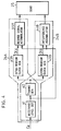
- Fig. 1 illustrates in block form an embodiment of the mobile station 20 according to the present invention and a base station 30. Since the present invention concerns the reception by the mobile station, there are shown only the transmitting section of the base station 30 and the receiving section of the mobile station 20.
- the base station 30 is provided with: a demultiplex part 32 whereby a multiplexed speech signal fed thereto from a switch 50 via an interface 31 is demultiplexed under the control of a control unit 33 for connection to unoccupied or free communication channels; PN code generating parts 360 through 36 m for generating spreading codes PN0, PN1, ..., PN m of the same code length (of N chips) corresponding to the respective channels; multipliers 350 through 35 m for multiplying information of the respective channels by the corresponding spreading codes to generate spectrum-spread information; a modulator 37 for modulating a carrier by a composite signal composed of the spread information; and an amplifier 38 for amplifying the modulated carrier for transmission.
- the PN code generating parts 360 through 36 m each have a PN generator circuit composed of such a shift register and an exclusive OR circuit as referred to previously and generates, in synchronization with a chip clock CKp from a timing signal generating part 34, a sequence of chips (the chip number N being substantially in the range of between 100 and 300, for example) of each PN code with a period Tp in a repeating cyclic order.
- a PN generator circuit composed of such a shift register and an exclusive OR circuit as referred to previously and generates, in synchronization with a chip clock CKp from a timing signal generating part 34, a sequence of chips (the chip number N being substantially in the range of between 100 and 300, for example) of each PN code with a period Tp in a repeating cyclic order.
- a PN generator circuit composed of such a shift register and an exclusive OR circuit as referred to previously and generates, in synchronization with a chip clock CKp from a timing signal generating part 34
- the repetition period Tp of each PN code and the bit period of the signal to be spread are chosen to be the same and each bit of the input signal is spread by N chips of the PN code.
- the spreading code PN0 is assigned to the control channel and its information is provided from the control unit 33.
- the modulator 37 is, for instance, a QPSK modulator, in which case, based on spread information, it modulates a carrier into a complex signal composed of an in-phase component I and a quadrature component Q.
- the modulated carrier is transmitted after being amplified by the amplifier 38.
- channels CH0 through CH m for transmission from the base station 30 are respectively assigned the different spreading codes PN0 through PN m of the same code length (the chip number N).
- the control channel CH0 is used to transmit, at all times, a control signal containing information on the control channel configuration, base station identifying information, control channel information (channel numbers) of adjacent channels, paging information, etc.
- the communication channels CH1 through CH m are used to transmit speech information to respective mobile stations from the base station 30.
- a receiver 21 synchronously detects the received wave and outputs, as a received signal S R , an in-phase component I and a quadrature component Q when the mobile communication system uses the QPSK modulation scheme, for instance.
- a correlation detector 22 detects the magnitude of the cross-correlation between the spreading code PN corresponding to a desired channel, provided from a PN code generating part 23, and the received signal S R .
- a desired signal level detector or intra-window receiving level detector 24A of a level detecting part 24 detects the instant when the output from the correlation detector 22 becomes maximum and the output level at that time.
- the level detecting part 24 further includes an interference level detector 24B characteristic of the present invention, which outputs, as an interference signal level, the value of correlation for an interference signal contained in the output from the correlation detector 22.
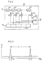
- the correlation detector 22 may be formed by such a matched filter as shown in Fig. 2.
- the synchronously detected output from the receiver 21 is input into N series-connected delay stages 22D (i.e. a shift register with N shift stages) and outputs from these delay stages 22D are respectively fed to N multipliers 22M, wherein they are multiplied by the values of the corresponding chips of the PN code (i.e. the spreading code) provided to an N-stage shift register 22R from the PN code generating part 23.
- the resulting multiplier outputs are added together by an adder 22S, whose output is provided as a correlation value C R .
- an adder 22S whose output is provided as a correlation value C R .
- such a correlation detector 22 is provided for each of the in-phase component I and the quadrature component Q to obtain the correlation output C R individually.
- the spreading code set in the shift register 22R of the correlation detector 22 is the same as the spreading code PN0 that is generated by the PN code generating part 360 of the base station 30 in a repeating cyclic sequence. Since the PN code generating part 360 of the base station 30 generates the PN code PN0 chip by chip in a repeating cyclic order, the PN code PN0 becomes instantaneously in-phase with the PN code set in the shift register 22R at a certain moment in each period Tp of the PN code (i.e.
- the correlation between the afore-said spreading code component in the received signal and the PN code set in the shift register 22R of the correlation detector 22 becomes maximum or highest and the output level C R of the correlation detector 22 reaches its peak value as shown in Fig. 3.
- the output level C R becomes maximum with the period Tp.
- the period a-b in which the output from the correlation detector 22 reaches its peak will hereinafter be referred to as a window and the detected level in the window represents the despread received signal in the selected channel.
- the inter-window receiving level detector (or desired signal level detector) 24A detects, in a search mode, the level in the window at which the output (or correlation value) C R from the correlation detector 22 becomes maximum and the detected output is provided to a control part 25.
- the interference level detector 24B detects the power level of the output from the correlation detector 22 outside the window and the detected output is also applied to the control part 25.
- the PN code generating part 23 has prestored, for example, in its internal storage (not shown) the spreading codes corresponding to the control and communication channels, for instance, and reads out a specified one of the spreading codes and set it in the shift register 22R of the correlation detector 22 under the control of the control part 25.
- control part 25 fetches therein the outputs from the level detectors 24A and 24B in the case where the spreading code corresponding to the control channel of each base station is set in the shift register 22R (that is, in the case of despreading). Based on such measured data by the level detectors 24A and 24B, the control part 25 estimates a more accurate receiving level in the control channel described later on.
- Control signal data for the control channel, generated in the control unit 33 of the base station 30 is spread, in the multiplier 350, by the level measuring spreading code PN0 from the PN code generating part 360 and is combined with spread signals from the multipliers, for example, 351 and 354, of the currently-used communication channels, and the combined signal is superimposed on a carrier signal in the modulator 37.
- the modulated output signal from the modulator 37 is amplified by the amplifier 38 and then transmitted.
- the mobile station 20 When placed in the initial state by turning on its power supply, the mobile station 20 needs first to identify the base station of the cell wherein it is currently staying. To this end, the spreading codes corresponding to control channels of respective base stations are sequentially generated by the PN code generating part 23 and set in the shift register 22R of the correlation detector 22, then received signals from the respective base stations are despread by the spreading codes in a sequential order and the received levels of the control signals from the base stations are measured (a measurement mode). In order for the mobile station 20 to select the nearest one of the base stations, the spreading codes corresponding to the control channels of the respective cells are sequentially set in the shift register 22R and the levels of the correlation detected outputs are measured which reach their peaks in the window a-b as shown in Fig.
- the spreading code which provides the maximum or highest received level is selected.
- the cross-correlation between these spreading codes is not completely reduced to zero, besides the cross-correlation differs with combinations of the spreading codes.
- the control channel received level of another spreading code is contained in the measured received level in accordance with the value of cross-correlation between the spreading code set in the register 22R and the said another spreading code. Hence, the received level thus measured does not reflect the correct received level in the said control channel.
- the received level of the desired signal in the window could be estimated as described below with reference to Fig. 3.
- the total power Pw in the window a-b after despreading is expressed by the following equation: and the power Pw is obtained by adding together levels measured at respective sample points in the window a-b.
- the total interference signal power P I distributed outside the window after despreading is expressed by the following equation:
- the measured values are provided to the control part 25 and the total power Psw of the desired signal during the period Tp is calculated based on equation (4). In this way, the corrected received level of the desired signal in the control channel is obtained. Similar processing is carried out for other control channels as well.
- the spreading codes corresponding to them are set in the shift register 22R of the correlation detector 22 in a sequential order; their respective received levels are detected; those of the thus detected received levels which are above a predetermined threshold value are corrected through calculation as described above; and the control channel of the spreading code that provided the highest one of such corrected received levels is selected.
- the desired signal level detector 24A and the interference level detector 24B can be constructed as shown in Fig. 4, for instance.
- the output C R from the correlation detector 22 is provided to a received level detecting part 41, wherein its amplitude is squared. (In the case of the QPSK scheme, the sum of squared values of the I component output C RI and the Q component output C RQ , that is, C RI 2 + C RQ 2, is calculated.)
- the output from the received level detecting part 41 is applied to a timing generating part 42, which generates a gate signal S G of the timing that defines the window a-b of a predetermined time width (in the range of between one and several chips) centering at the instant when the received level in each period Tp reaches its peak (see Fig.
- the timing generating part 42 generates a sampling clock CKs of a rate equal to or higher than the chip rate is synchronization with the peak of the received level.
- a timing generating part 42 can be configured by such a phase locked loop (PLL) as shown in Fig. 5.
- the output from the received level detecting part 41 is applied to the one of a phase comparator 421, wherein it is compared in phase with a reference signal fed to the other input of the comparator 421.
- the output from the phase comparator 421 is provided via a loop filter (or low-pass filter) 422 to a VCO 423 to control its oscillation frequency F.
- the frequency F of the output from the VCO 323 (Fig. 6-Row B) is divided by a frequency divider 424 down to F/N (Fig. 6-Row C).
- the thus frequency-divided output is delayed by a delay element 425 for one-half the chip period Tp/N and then fed as the reference signal to the phase comparator 421.
- a pulse of the same width as the chip width is generated and applied to a gate 43A as a gate signal S G shown in Fig. 6-Row D.
- the gate signal S G is also fed to a gate 43B after being inverted by an inverter 437 (Fig. 6-Row E).
- the gate 43A permits the passage therethrough of the sampling clocks CKs in the window a-b of one chip width as an intra-window sampling clock CKd signal (Fig.
- sampling clocks CKs outside the window as an extra-window sampling clock CKi signal (Fig. 6-Row G).
- the sampling clocks CKd and CKi having passed through the gates 43A and 43B are applied to an intra-window level or desired signal accumulator 44A and an interference signal accumulator 44B in Fig. 4, respectively.
- Such a PLL circuit as shown in Fig. 5 may also be formed by a digital circuit.
- the desired signal accumulator 44A and the interference signal accumulator 44B are supplied with the output level of the received level detecting part 41 and accumulate the input levels for the period Tp upon each application thereto of the sampling clocks CKd and CKi.
- the accumulated output from the desired signal accumulator 44A becomes the afore-mentioned intra-window total power Pw after despreading and the accumulated output from the interference signal adder 44B becomes the total power P I of the interference signal outside the window after despreading which is expressed by the sum of the first and second terms on the righthand side of equation (3).
- the outputs from the accumulators 44A and 44B are applied to the control part 25. Based on these pieces of data provided thereto, the control part 25 calculates the received level of the desired control channel by equation (4) as described previously.
- the mobile station By subtracting the interference signal level from the received level in the window as mentioned above, the influence of the interference signal is lessened and the correct base station and consequently the visited cell can be selected.
- the mobile station there are stored spreading codes (for level monitoring use) corresponding to the control channels of all cells in the service area.
- the mobile station searches all the control channels and, after determination of the visited cell, stores information on the control channels of the adjoining cells obtained from the selected control channel and searches control channels for the spreading codes corresponding to the stored control channels of the adjoining cells.
- the received level of the control channel to be compared is the value obtained by subtracting the interference signal power from the total received level in the window
- the ratio Pw/P IW between the total received level in the window expressed by equation (1) and the interference signal power P IW is also possible to obtain, for each control channel, the ratio Pw/P IW between the total received level in the window expressed by equation (1) and the interference signal power P IW and select the control channel corresponding to the maximum one of such ratios.
- the total received level in the window and the interference signal level outside the window are used and the signal for comparison from which the influence of the interference signal has been removed is used as the criterion for the determination of the visited cell.
- the influence of the interference wave that gets mixed during measurement of the received level is eliminated -- this makes the selection of the base station less faulty than in the case of measuring the received level alone.
- the selection of the nearest base station increases the margin of transmitting power control of the mobile station, causing an increase in the channel capacity by the transmitting power control effect.
Landscapes
- Engineering & Computer Science (AREA)
- Computer Networks & Wireless Communication (AREA)
- Signal Processing (AREA)
- Computer Security & Cryptography (AREA)
- Mobile Radio Communication Systems (AREA)
Applications Claiming Priority (3)
| Application Number | Priority Date | Filing Date | Title |
|---|---|---|---|
| JP4931893A JP2802870B2 (ja) | 1993-03-10 | 1993-03-10 | 符号分割多重移動通信機及び符号分割多重移動通信のセル選択方法 |
| JP49318/93 | 1993-03-10 | ||
| JP4931893 | 1993-03-10 |
Publications (3)
| Publication Number | Publication Date |
|---|---|
| EP0615355A2 true EP0615355A2 (de) | 1994-09-14 |
| EP0615355A3 EP0615355A3 (de) | 1995-04-05 |
| EP0615355B1 EP0615355B1 (de) | 2001-09-26 |
Family
ID=12827624
Family Applications (1)
| Application Number | Title | Priority Date | Filing Date |
|---|---|---|---|
| EP19940103422 Expired - Lifetime EP0615355B1 (de) | 1993-03-10 | 1994-03-07 | Mobilstation und Zellwahlverfahren für Mobilkommunikation mit Kodemultiplexvielfachzugriff |
Country Status (5)
| Country | Link |
|---|---|
| US (1) | US5420850A (de) |
| EP (1) | EP0615355B1 (de) |
| JP (1) | JP2802870B2 (de) |
| CA (1) | CA2116601C (de) |
| DE (1) | DE69428388T2 (de) |
Cited By (10)
| Publication number | Priority date | Publication date | Assignee | Title |
|---|---|---|---|---|
| GB2318952A (en) * | 1996-10-29 | 1998-05-06 | Motorola Inc | Fast pilot channel acquisition using a matched filter in a CDMA radiotelephone |
| WO1998019477A1 (en) * | 1996-10-29 | 1998-05-07 | Samsung Electronics Co., Ltd. | Circuit for eliminating external interference signals in code division multiple access mobile phone |
| EP0954111A1 (de) * | 1998-04-27 | 1999-11-03 | Siemens Aktiengesellschaft | Funkkommunikationsanordnung und Verfahren zur Übertragung von Steuerdaten zur Verwendung in demselben |
| US6151502A (en) * | 1997-01-29 | 2000-11-21 | Qualcomm Incorporated | Method and apparatus for performing soft hand-off in a wireless communication system |
| EP1058402A1 (de) * | 1999-06-02 | 2000-12-06 | Commissariat A L'energie Atomique | Verfahren zur Verarbeitung einer Kanalimpulsantwort mit adaptiver Schwelle und entsprechender Empfänger |
| EP1204282A4 (de) * | 2000-05-26 | 2002-10-23 | Matsushita Electric Industrial Co Ltd | Funkbasisstationsvorrichtung und funkkommunikationsverfahren |
| RU2242089C2 (ru) * | 1997-07-01 | 2004-12-10 | Квэлкомм Инкорпорейтед | Абонентское устройство и способ его использования в системе беспроводной связи |
| USRE39177E1 (en) * | 1997-01-29 | 2006-07-11 | Qualcomm, Inc. | Method and apparatus for performing soft hand-off in a wireless communication system |
| EP1696688A1 (de) * | 2000-07-10 | 2006-08-30 | Interdigital Technology Corporation | Kodeleistungsmessung für dynamische Kanalzuwendung |
| US8213485B2 (en) | 1996-05-28 | 2012-07-03 | Qualcomm Incorporated | High rate CDMA wireless communication system using variable sized channel codes |
Families Citing this family (50)
| Publication number | Priority date | Publication date | Assignee | Title |
|---|---|---|---|---|
| US5572514A (en) * | 1993-06-30 | 1996-11-05 | Casio Computer Co., Ltd. | Spread spectrum communication system capable of detecting occupying state of channel by off-communication terminal |
| JP2526510B2 (ja) * | 1993-10-22 | 1996-08-21 | 日本電気株式会社 | 無線デ―タ通信装置 |
| JP2636712B2 (ja) * | 1993-12-08 | 1997-07-30 | 日本電気株式会社 | 移動通信装置 |
| JP2689890B2 (ja) * | 1993-12-30 | 1997-12-10 | 日本電気株式会社 | スペクトラム拡散受信機 |
| US5559789A (en) | 1994-01-31 | 1996-09-24 | Matsushita Electric Industrial Co., Ltd. | CDMA/TDD Radio Communication System |
| CN1235436C (zh) * | 1994-05-20 | 2006-01-04 | Ntt移动通信网株式会社 | 移动通信方法和使用可靠性信息的基站侧子系统装置 |
| US5577022A (en) * | 1994-11-22 | 1996-11-19 | Qualcomm Incorporated | Pilot signal searching technique for a cellular communications system |
| JPH08265817A (ja) * | 1995-03-24 | 1996-10-11 | Uniden Corp | 受信装置 |
| TW347626B (en) * | 1995-03-27 | 1998-12-11 | Sanyo Electric Co | Spectrum diffusion signal receiver |
| FI98171C (fi) * | 1995-05-24 | 1997-04-25 | Nokia Telecommunications Oy | Menetelmä pilottikanavien lähettämiseksi ja solukkoradiojärjestelmä |
| EP1229752B1 (de) * | 1995-05-31 | 2004-10-13 | NTT DoCoMo, Inc. | Verfahren, System und Mobilstationsvorrichtung zur CDMA-Mobilkommunikation |
| US6111911A (en) * | 1995-06-07 | 2000-08-29 | Sanconix, Inc | Direct sequence frequency ambiguity resolving receiver |
| US5790588A (en) * | 1995-06-07 | 1998-08-04 | Ntt Mobile Communications Network, Inc. | Spread spectrum transmitter and receiver employing composite spreading codes |
| US5671221A (en) * | 1995-06-14 | 1997-09-23 | Sharp Microelectronics Technology, Inc. | Receiving method and apparatus for use in a spread-spectrum communication system |
| JP2863993B2 (ja) * | 1995-06-22 | 1999-03-03 | 松下電器産業株式会社 | Cdma無線多重送信装置およびcdma無線多重伝送装置およびcdma無線受信装置およびcdma無線多重送信方法 |
| US6940840B2 (en) | 1995-06-30 | 2005-09-06 | Interdigital Technology Corporation | Apparatus for adaptive reverse power control for spread-spectrum communications |
| ZA965340B (en) | 1995-06-30 | 1997-01-27 | Interdigital Tech Corp | Code division multiple access (cdma) communication system |
| US7020111B2 (en) * | 1996-06-27 | 2006-03-28 | Interdigital Technology Corporation | System for using rapid acquisition spreading codes for spread-spectrum communications |
| US7072380B2 (en) * | 1995-06-30 | 2006-07-04 | Interdigital Technology Corporation | Apparatus for initial power control for spread-spectrum communications |
| US6788662B2 (en) * | 1995-06-30 | 2004-09-07 | Interdigital Technology Corporation | Method for adaptive reverse power control for spread-spectrum communications |
| US6885652B1 (en) | 1995-06-30 | 2005-04-26 | Interdigital Technology Corporation | Code division multiple access (CDMA) communication system |
| US7123600B2 (en) | 1995-06-30 | 2006-10-17 | Interdigital Technology Corporation | Initial power control for spread-spectrum communications |
| US6831905B1 (en) * | 1995-06-30 | 2004-12-14 | Interdigital Technology Corporation | Spread spectrum system assigning information signals to message-code signals |
| US6816473B2 (en) | 1995-06-30 | 2004-11-09 | Interdigital Technology Corporation | Method for adaptive forward power control for spread-spectrum communications |
| US7929498B2 (en) | 1995-06-30 | 2011-04-19 | Interdigital Technology Corporation | Adaptive forward power control and adaptive reverse power control for spread-spectrum communications |
| US5907813A (en) * | 1995-11-30 | 1999-05-25 | Qualcomm Incorporated | Signal acquisition in a wireless communication system by transmitting repeated access probes from a terminal to a hub |
| US6301287B1 (en) * | 1995-12-06 | 2001-10-09 | Conexant Systems, Inc. | Method and apparatus for signal quality estimation in a direct sequence spread spectrum communication system |
| JPH09238093A (ja) * | 1996-02-29 | 1997-09-09 | Sanyo Electric Co Ltd | スペクトル拡散受信装置 |
| US5930230A (en) | 1996-05-28 | 1999-07-27 | Qualcomm Incorporated | High data rate CDMA wireless communication system |
| JP3361694B2 (ja) * | 1996-06-07 | 2003-01-07 | 株式会社エヌ・ティ・ティ・ドコモ | Cdma移動通信システムにおけるパイロットチャネル送信およびセル選択方法、移動局 |
| US5790589A (en) * | 1996-08-14 | 1998-08-04 | Qualcomm Incorporated | System and method for rapidly reacquiring a pilot channel |
| EP0878973B1 (de) * | 1996-10-18 | 2005-03-02 | Matsushita Electric Industrial Co., Ltd | Funkkommunikationssystem und Verfahren zur Ausführung eines Handovers mobiler Endgeräte durch Auswertung von TPC-Signalen |
| US6134569A (en) * | 1997-01-30 | 2000-10-17 | Sharp Laboratories Of America, Inc. | Polyphase interpolator/decimator using continuous-valued, discrete-time signal processing |
| US6075807A (en) * | 1997-03-25 | 2000-06-13 | Intermec Ip Corp. | Windowed digital matched filter circuit for power reduction in battery-powered CDMA radios |
| US6078573A (en) * | 1997-04-11 | 2000-06-20 | Research Foundation Of State University Of New York | Circuitry and method for demodulating code division multiple access (CDMA) signals |
| FI108178B (fi) * | 1997-12-16 | 2001-11-30 | Nokia Networks Oy | Tietoliikenneverkon kapasiteetin kasvattaminen |
| US6529492B1 (en) | 1997-12-30 | 2003-03-04 | Matsushita Electric Industrial Co., Ltd. | CDMA radio multiplex transmitting device and a CDMA radio multiplex receiving device |
| KR100277761B1 (ko) * | 1998-06-25 | 2001-01-15 | 윤종용 | 셀룰러 시스템에서 이동 단말기의 탐색 범위설정 방법 |
| JP3149399B2 (ja) | 1998-09-24 | 2001-03-26 | 松下電器産業株式会社 | Cdma基地局装置及びコード割当方法 |
| US6480558B1 (en) * | 1999-03-17 | 2002-11-12 | Ericsson Inc. | Synchronization and cell search methods and apparatus for wireless communications |
| US7151761B1 (en) * | 1999-03-19 | 2006-12-19 | Telefonaktiebolaget L M Ericsson (Publ) | Code reservation for interference measurement in a CDMA radiocommunication system |
| FR2791495B1 (fr) * | 1999-03-26 | 2001-05-04 | France Telecom | Procede de synchronisation de rythme d'un signal numerique |
| TW463481B (en) * | 1999-04-28 | 2001-11-11 | Fujitsu Ltd | Cell search method, communication synchronization apparatus, portable terminal apparatus, and recording medium |
| KR100513710B1 (ko) * | 1999-05-25 | 2005-09-07 | 삼성전자주식회사 | Cdma 통신시스템의 코드동기 취득방법 및 그 장치 |
| JP2001086034A (ja) | 1999-09-14 | 2001-03-30 | Nec Corp | とまり木チャネル検出回路における拡散コード検出方法およびその回路 |
| US6556621B1 (en) * | 2000-03-29 | 2003-04-29 | Time Domain Corporation | System for fast lock and acquisition of ultra-wideband signals |
| EP1299956B1 (de) | 2000-07-10 | 2005-09-14 | Interdigital Technology Corporation | Kodeleistungsmessung für dynamische kanalzuwendung |
| US7339955B2 (en) * | 2000-09-25 | 2008-03-04 | Pulse-Link, Inc. | TDMA communication method and apparatus using cyclic spreading codes |
| US8964692B2 (en) * | 2008-11-10 | 2015-02-24 | Qualcomm Incorporated | Spectrum sensing of bluetooth using a sequence of energy detection measurements |
| WO2016119112A1 (zh) * | 2015-01-26 | 2016-08-04 | 华为技术有限公司 | 一种选择控制信道的方法和装置 |
Family Cites Families (4)
| Publication number | Priority date | Publication date | Assignee | Title |
|---|---|---|---|---|
| JPH01117432A (ja) * | 1987-10-30 | 1989-05-10 | Canon Inc | 移動通信方式 |
| US5109390A (en) * | 1989-11-07 | 1992-04-28 | Qualcomm Incorporated | Diversity receiver in a cdma cellular telephone system |
| DE4121356C2 (de) * | 1991-06-28 | 1995-01-19 | Siemens Ag | Verfahren und Einrichtung zur Separierung eines Signalgemisches |
| US5311544A (en) * | 1992-11-19 | 1994-05-10 | Samsung Electronics Co., Ltd. | Receiver of a direct sequence spread spectrum system |
-
1993
- 1993-03-10 JP JP4931893A patent/JP2802870B2/ja not_active Expired - Lifetime
-
1994
- 1994-02-28 CA CA 2116601 patent/CA2116601C/en not_active Expired - Fee Related
- 1994-03-01 US US08/203,396 patent/US5420850A/en not_active Expired - Lifetime
- 1994-03-07 DE DE69428388T patent/DE69428388T2/de not_active Expired - Fee Related
- 1994-03-07 EP EP19940103422 patent/EP0615355B1/de not_active Expired - Lifetime
Cited By (20)
| Publication number | Priority date | Publication date | Assignee | Title |
|---|---|---|---|---|
| US8588277B2 (en) | 1996-05-28 | 2013-11-19 | Qualcomm Incorporated | High data rate CDMA wireless communication system using variable sized channel codes |
| US8213485B2 (en) | 1996-05-28 | 2012-07-03 | Qualcomm Incorporated | High rate CDMA wireless communication system using variable sized channel codes |
| GB2318952B (en) * | 1996-10-29 | 2001-06-20 | Motorola Inc | Method and apparatus for fast pilot channel acquisition using a matched filter in a CDMA radiotelephone |
| WO1998019477A1 (en) * | 1996-10-29 | 1998-05-07 | Samsung Electronics Co., Ltd. | Circuit for eliminating external interference signals in code division multiple access mobile phone |
| GB2333667A (en) * | 1996-10-29 | 1999-07-28 | Samsung Electronics Co Ltd | Circuit for eliminating external interference signals in code division multiple access mobile phone |
| US5950131A (en) * | 1996-10-29 | 1999-09-07 | Motorola, Inc. | Method and apparatus for fast pilot channel acquisition using a matched filter in a CDMA radiotelephone |
| AU716099B2 (en) * | 1996-10-29 | 2000-02-17 | Samsung Electronics Co., Ltd. | Circuit for eliminating external interference signals in code division multiple access mobile phone |
| GB2318952A (en) * | 1996-10-29 | 1998-05-06 | Motorola Inc | Fast pilot channel acquisition using a matched filter in a CDMA radiotelephone |
| GB2333667B (en) * | 1996-10-29 | 2001-02-14 | Samsung Electronics Co Ltd | Circuit for eliminating external interference signals in code division multiple access mobile phone |
| DE19745432C2 (de) * | 1996-10-29 | 2001-05-03 | Motorola Inc | Verfahren und Vorrichtung zur schnellen Pilotkanalerfassung unter Verwendung eines Optimalfilters bei einem CDMA-Sprechfunkgerät |
| US6151502A (en) * | 1997-01-29 | 2000-11-21 | Qualcomm Incorporated | Method and apparatus for performing soft hand-off in a wireless communication system |
| USRE39177E1 (en) * | 1997-01-29 | 2006-07-11 | Qualcomm, Inc. | Method and apparatus for performing soft hand-off in a wireless communication system |
| RU2242089C2 (ru) * | 1997-07-01 | 2004-12-10 | Квэлкомм Инкорпорейтед | Абонентское устройство и способ его использования в системе беспроводной связи |
| WO1999056402A1 (en) * | 1998-04-27 | 1999-11-04 | Siemens Aktiengesellschaft | Radio communications apparatus and method of communicating control data for use in a radio communications apparatus |
| EP0954111A1 (de) * | 1998-04-27 | 1999-11-03 | Siemens Aktiengesellschaft | Funkkommunikationsanordnung und Verfahren zur Übertragung von Steuerdaten zur Verwendung in demselben |
| US6748007B1 (en) | 1999-06-02 | 2004-06-08 | Commissariat A L'energie Atomique | Method of processing a pulse response with an adaptive threshold and corresponding receiver |
| FR2794586A1 (fr) * | 1999-06-02 | 2000-12-08 | Commissariat Energie Atomique | Procede de traitement d'une reponse impulsionnelle avec seuil adaptatif et recepteur correspondant |
| EP1058402A1 (de) * | 1999-06-02 | 2000-12-06 | Commissariat A L'energie Atomique | Verfahren zur Verarbeitung einer Kanalimpulsantwort mit adaptiver Schwelle und entsprechender Empfänger |
| EP1204282A4 (de) * | 2000-05-26 | 2002-10-23 | Matsushita Electric Industrial Co Ltd | Funkbasisstationsvorrichtung und funkkommunikationsverfahren |
| EP1696688A1 (de) * | 2000-07-10 | 2006-08-30 | Interdigital Technology Corporation | Kodeleistungsmessung für dynamische Kanalzuwendung |
Also Published As
| Publication number | Publication date |
|---|---|
| CA2116601C (en) | 1998-11-10 |
| EP0615355B1 (de) | 2001-09-26 |
| US5420850A (en) | 1995-05-30 |
| CA2116601A1 (en) | 1994-09-11 |
| JPH06268576A (ja) | 1994-09-22 |
| DE69428388D1 (de) | 2001-10-31 |
| DE69428388T2 (de) | 2002-05-02 |
| EP0615355A3 (de) | 1995-04-05 |
| JP2802870B2 (ja) | 1998-09-24 |
Similar Documents
| Publication | Publication Date | Title |
|---|---|---|
| EP0615355B1 (de) | Mobilstation und Zellwahlverfahren für Mobilkommunikation mit Kodemultiplexvielfachzugriff | |
| EP0821495B1 (de) | Verfahren und Gerät zum Empfangen von CDMA Funkübertragungssignalen | |
| US5544155A (en) | Method of synchronization for code division multiple access radiotelephone communications | |
| US5654980A (en) | Method for controlling a receiver, and a receiver | |
| US6625200B1 (en) | Multi-stage CDMA synchronization with parallel execution | |
| KR0143825B1 (ko) | 슬라이딩 상관기 | |
| EP0940927B1 (de) | Zellularsystem, mobiles tragbares Gerät, Basisstation und Verfahren zur optimalen Pfadbestimmung | |
| US7224720B2 (en) | Correlator and delay lock loop circuit | |
| EP0848503B1 (de) | CDMA chip Synchronisationsschaltung | |
| KR100292097B1 (ko) | Cdma통신시스템 | |
| US5966402A (en) | Method and apparatus for detecting pilot signals and subscriber | |
| US6567391B1 (en) | Device and method for communicating reverse pilot signal in mobile communication system | |
| EP1094679B1 (de) | Übertragungsverfahren eines Abwartspilotkanals in einem CDMA-Mobilkommunikationssystem, und CDMA-Kommunikationssystem | |
| US5699380A (en) | Spread spectrum communication terminal apparatus in CDMA cellular telephone system | |
| KR20010031050A (ko) | 다중 사용자 통신 시스템의 다층 pn 코드 확산 | |
| EP0889600A2 (de) | Synchronisation in Spreizspektrumnachrichtenübertragung | |
| KR100361408B1 (ko) | Cdma 통신을 위한 동기포착회로 | |
| US7106783B2 (en) | Method and apparatus for searching multipaths of mobile communication system | |
| EP1667344A1 (de) | Spreizband- Nachrichtenübertragungssystem und Verfahren zur Verbindungsübergabe in diesem | |
| US6954485B1 (en) | CDMA baseband receiver capable of establishing synchronization with peripheral base stations | |
| KR100525543B1 (ko) | 트랙킹 기능을 가진 프레임 동기화 및 코드 그룹 검출기 | |
| US20100002678A1 (en) | Mobile radio terminal and radio communication method | |
| KR100232825B1 (ko) | 가정용 무선전화기 홈스테이션의 파이롯트 pn옵셋 검출장치 및 그 방법 | |
| JP2986401B2 (ja) | パイロットチャネル用拡散コード配置方法および基地局装置と移動局装置 | |
| US20040029547A1 (en) | Radio mobile device |
Legal Events
| Date | Code | Title | Description |
|---|---|---|---|
| PUAI | Public reference made under article 153(3) epc to a published international application that has entered the european phase |
Free format text: ORIGINAL CODE: 0009012 |
|
| 17P | Request for examination filed |
Effective date: 19940307 |
|
| AK | Designated contracting states |
Kind code of ref document: A2 Designated state(s): DE FR GB SE |
|
| PUAL | Search report despatched |
Free format text: ORIGINAL CODE: 0009013 |
|
| AK | Designated contracting states |
Kind code of ref document: A3 Designated state(s): DE FR GB SE |
|
| 17Q | First examination report despatched |
Effective date: 19990505 |
|
| GRAG | Despatch of communication of intention to grant |
Free format text: ORIGINAL CODE: EPIDOS AGRA |
|
| GRAG | Despatch of communication of intention to grant |
Free format text: ORIGINAL CODE: EPIDOS AGRA |
|
| GRAH | Despatch of communication of intention to grant a patent |
Free format text: ORIGINAL CODE: EPIDOS IGRA |
|
| GRAH | Despatch of communication of intention to grant a patent |
Free format text: ORIGINAL CODE: EPIDOS IGRA |
|
| GRAA | (expected) grant |
Free format text: ORIGINAL CODE: 0009210 |
|
| AK | Designated contracting states |
Kind code of ref document: B1 Designated state(s): DE FR GB SE |
|
| REF | Corresponds to: |
Ref document number: 69428388 Country of ref document: DE Date of ref document: 20011031 |
|
| ET | Fr: translation filed | ||
| REG | Reference to a national code |
Ref country code: GB Ref legal event code: IF02 |
|
| PLBE | No opposition filed within time limit |
Free format text: ORIGINAL CODE: 0009261 |
|
| STAA | Information on the status of an ep patent application or granted ep patent |
Free format text: STATUS: NO OPPOSITION FILED WITHIN TIME LIMIT |
|
| 26N | No opposition filed | ||
| PGFP | Annual fee paid to national office [announced via postgrant information from national office to epo] |
Ref country code: DE Payment date: 20070301 Year of fee payment: 14 |
|
| PGFP | Annual fee paid to national office [announced via postgrant information from national office to epo] |
Ref country code: GB Payment date: 20070307 Year of fee payment: 14 Ref country code: SE Payment date: 20070307 Year of fee payment: 14 |
|
| PGFP | Annual fee paid to national office [announced via postgrant information from national office to epo] |
Ref country code: FR Payment date: 20070308 Year of fee payment: 14 |
|
| EUG | Se: european patent has lapsed | ||
| GBPC | Gb: european patent ceased through non-payment of renewal fee |
Effective date: 20080307 |
|
| REG | Reference to a national code |
Ref country code: FR Ref legal event code: ST Effective date: 20081125 |
|
| PG25 | Lapsed in a contracting state [announced via postgrant information from national office to epo] |
Ref country code: SE Free format text: LAPSE BECAUSE OF NON-PAYMENT OF DUE FEES Effective date: 20080308 Ref country code: DE Free format text: LAPSE BECAUSE OF NON-PAYMENT OF DUE FEES Effective date: 20081001 |
|
| PG25 | Lapsed in a contracting state [announced via postgrant information from national office to epo] |
Ref country code: FR Free format text: LAPSE BECAUSE OF NON-PAYMENT OF DUE FEES Effective date: 20080331 |
|
| PG25 | Lapsed in a contracting state [announced via postgrant information from national office to epo] |
Ref country code: GB Free format text: LAPSE BECAUSE OF NON-PAYMENT OF DUE FEES Effective date: 20080307 |