EP0615831A2 - Procédé et dispositif pour la fabrication de boîtiers ou d'objets similaires et boîtiers ainsi obtenus - Google Patents
Procédé et dispositif pour la fabrication de boîtiers ou d'objets similaires et boîtiers ainsi obtenus Download PDFInfo
- Publication number
- EP0615831A2 EP0615831A2 EP94103425A EP94103425A EP0615831A2 EP 0615831 A2 EP0615831 A2 EP 0615831A2 EP 94103425 A EP94103425 A EP 94103425A EP 94103425 A EP94103425 A EP 94103425A EP 0615831 A2 EP0615831 A2 EP 0615831A2
- Authority
- EP
- European Patent Office
- Prior art keywords
- concave
- convex
- flat
- area
- housing
- Prior art date
- Legal status (The legal status is an assumption and is not a legal conclusion. Google has not performed a legal analysis and makes no representation as to the accuracy of the status listed.)
- Granted
Links
Images







Classifications
-
- B—PERFORMING OPERATIONS; TRANSPORTING
- B29—WORKING OF PLASTICS; WORKING OF SUBSTANCES IN A PLASTIC STATE IN GENERAL
- B29C—SHAPING OR JOINING OF PLASTICS; SHAPING OF MATERIAL IN A PLASTIC STATE, NOT OTHERWISE PROVIDED FOR; AFTER-TREATMENT OF THE SHAPED PRODUCTS, e.g. REPAIRING
- B29C53/00—Shaping by bending, folding, twisting, straightening or flattening; Apparatus therefor
- B29C53/02—Bending or folding
- B29C53/04—Bending or folding of plates or sheets
-
- B—PERFORMING OPERATIONS; TRANSPORTING
- B29—WORKING OF PLASTICS; WORKING OF SUBSTANCES IN A PLASTIC STATE IN GENERAL
- B29C—SHAPING OR JOINING OF PLASTICS; SHAPING OF MATERIAL IN A PLASTIC STATE, NOT OTHERWISE PROVIDED FOR; AFTER-TREATMENT OF THE SHAPED PRODUCTS, e.g. REPAIRING
- B29C65/00—Joining or sealing of preformed parts, e.g. welding of plastics materials; Apparatus therefor
- B29C65/02—Joining or sealing of preformed parts, e.g. welding of plastics materials; Apparatus therefor by heating, with or without pressure
-
- B—PERFORMING OPERATIONS; TRANSPORTING
- B29—WORKING OF PLASTICS; WORKING OF SUBSTANCES IN A PLASTIC STATE IN GENERAL
- B29C—SHAPING OR JOINING OF PLASTICS; SHAPING OF MATERIAL IN A PLASTIC STATE, NOT OTHERWISE PROVIDED FOR; AFTER-TREATMENT OF THE SHAPED PRODUCTS, e.g. REPAIRING
- B29C66/00—General aspects of processes or apparatus for joining preformed parts
- B29C66/01—General aspects dealing with the joint area or with the area to be joined
- B29C66/05—Particular design of joint configurations
- B29C66/10—Particular design of joint configurations particular design of the joint cross-sections
- B29C66/11—Joint cross-sections comprising a single joint-segment, i.e. one of the parts to be joined comprising a single joint-segment in the joint cross-section
- B29C66/112—Single lapped joints
-
- B—PERFORMING OPERATIONS; TRANSPORTING
- B29—WORKING OF PLASTICS; WORKING OF SUBSTANCES IN A PLASTIC STATE IN GENERAL
- B29C—SHAPING OR JOINING OF PLASTICS; SHAPING OF MATERIAL IN A PLASTIC STATE, NOT OTHERWISE PROVIDED FOR; AFTER-TREATMENT OF THE SHAPED PRODUCTS, e.g. REPAIRING
- B29C66/00—General aspects of processes or apparatus for joining preformed parts
- B29C66/01—General aspects dealing with the joint area or with the area to be joined
- B29C66/05—Particular design of joint configurations
- B29C66/10—Particular design of joint configurations particular design of the joint cross-sections
- B29C66/11—Joint cross-sections comprising a single joint-segment, i.e. one of the parts to be joined comprising a single joint-segment in the joint cross-section
- B29C66/114—Single butt joints
-
- B—PERFORMING OPERATIONS; TRANSPORTING
- B29—WORKING OF PLASTICS; WORKING OF SUBSTANCES IN A PLASTIC STATE IN GENERAL
- B29C—SHAPING OR JOINING OF PLASTICS; SHAPING OF MATERIAL IN A PLASTIC STATE, NOT OTHERWISE PROVIDED FOR; AFTER-TREATMENT OF THE SHAPED PRODUCTS, e.g. REPAIRING
- B29C66/00—General aspects of processes or apparatus for joining preformed parts
- B29C66/01—General aspects dealing with the joint area or with the area to be joined
- B29C66/05—Particular design of joint configurations
- B29C66/10—Particular design of joint configurations particular design of the joint cross-sections
- B29C66/11—Joint cross-sections comprising a single joint-segment, i.e. one of the parts to be joined comprising a single joint-segment in the joint cross-section
- B29C66/114—Single butt joints
- B29C66/1142—Single butt to butt joints
-
- B—PERFORMING OPERATIONS; TRANSPORTING
- B29—WORKING OF PLASTICS; WORKING OF SUBSTANCES IN A PLASTIC STATE IN GENERAL
- B29C—SHAPING OR JOINING OF PLASTICS; SHAPING OF MATERIAL IN A PLASTIC STATE, NOT OTHERWISE PROVIDED FOR; AFTER-TREATMENT OF THE SHAPED PRODUCTS, e.g. REPAIRING
- B29C66/00—General aspects of processes or apparatus for joining preformed parts
- B29C66/01—General aspects dealing with the joint area or with the area to be joined
- B29C66/05—Particular design of joint configurations
- B29C66/10—Particular design of joint configurations particular design of the joint cross-sections
- B29C66/12—Joint cross-sections combining only two joint-segments; Tongue and groove joints; Tenon and mortise joints; Stepped joint cross-sections
- B29C66/122—Joint cross-sections combining only two joint-segments, i.e. one of the parts to be joined comprising only two joint-segments in the joint cross-section
- B29C66/1222—Joint cross-sections combining only two joint-segments, i.e. one of the parts to be joined comprising only two joint-segments in the joint cross-section comprising at least a lapped joint-segment
-
- B—PERFORMING OPERATIONS; TRANSPORTING
- B29—WORKING OF PLASTICS; WORKING OF SUBSTANCES IN A PLASTIC STATE IN GENERAL
- B29C—SHAPING OR JOINING OF PLASTICS; SHAPING OF MATERIAL IN A PLASTIC STATE, NOT OTHERWISE PROVIDED FOR; AFTER-TREATMENT OF THE SHAPED PRODUCTS, e.g. REPAIRING
- B29C66/00—General aspects of processes or apparatus for joining preformed parts
- B29C66/01—General aspects dealing with the joint area or with the area to be joined
- B29C66/05—Particular design of joint configurations
- B29C66/10—Particular design of joint configurations particular design of the joint cross-sections
- B29C66/12—Joint cross-sections combining only two joint-segments; Tongue and groove joints; Tenon and mortise joints; Stepped joint cross-sections
- B29C66/122—Joint cross-sections combining only two joint-segments, i.e. one of the parts to be joined comprising only two joint-segments in the joint cross-section
- B29C66/1224—Joint cross-sections combining only two joint-segments, i.e. one of the parts to be joined comprising only two joint-segments in the joint cross-section comprising at least a butt joint-segment
-
- B—PERFORMING OPERATIONS; TRANSPORTING
- B29—WORKING OF PLASTICS; WORKING OF SUBSTANCES IN A PLASTIC STATE IN GENERAL
- B29C—SHAPING OR JOINING OF PLASTICS; SHAPING OF MATERIAL IN A PLASTIC STATE, NOT OTHERWISE PROVIDED FOR; AFTER-TREATMENT OF THE SHAPED PRODUCTS, e.g. REPAIRING
- B29C66/00—General aspects of processes or apparatus for joining preformed parts
- B29C66/01—General aspects dealing with the joint area or with the area to be joined
- B29C66/05—Particular design of joint configurations
- B29C66/10—Particular design of joint configurations particular design of the joint cross-sections
- B29C66/12—Joint cross-sections combining only two joint-segments; Tongue and groove joints; Tenon and mortise joints; Stepped joint cross-sections
- B29C66/124—Tongue and groove joints
- B29C66/1244—Tongue and groove joints characterised by the male part, i.e. the part comprising the tongue
- B29C66/12445—Tongue and groove joints characterised by the male part, i.e. the part comprising the tongue having the tongue on the side
-
- B—PERFORMING OPERATIONS; TRANSPORTING
- B29—WORKING OF PLASTICS; WORKING OF SUBSTANCES IN A PLASTIC STATE IN GENERAL
- B29C—SHAPING OR JOINING OF PLASTICS; SHAPING OF MATERIAL IN A PLASTIC STATE, NOT OTHERWISE PROVIDED FOR; AFTER-TREATMENT OF THE SHAPED PRODUCTS, e.g. REPAIRING
- B29C66/00—General aspects of processes or apparatus for joining preformed parts
- B29C66/01—General aspects dealing with the joint area or with the area to be joined
- B29C66/05—Particular design of joint configurations
- B29C66/10—Particular design of joint configurations particular design of the joint cross-sections
- B29C66/12—Joint cross-sections combining only two joint-segments; Tongue and groove joints; Tenon and mortise joints; Stepped joint cross-sections
- B29C66/124—Tongue and groove joints
- B29C66/1244—Tongue and groove joints characterised by the male part, i.e. the part comprising the tongue
- B29C66/12449—Tongue and groove joints characterised by the male part, i.e. the part comprising the tongue being asymmetric
-
- B—PERFORMING OPERATIONS; TRANSPORTING
- B29—WORKING OF PLASTICS; WORKING OF SUBSTANCES IN A PLASTIC STATE IN GENERAL
- B29C—SHAPING OR JOINING OF PLASTICS; SHAPING OF MATERIAL IN A PLASTIC STATE, NOT OTHERWISE PROVIDED FOR; AFTER-TREATMENT OF THE SHAPED PRODUCTS, e.g. REPAIRING
- B29C66/00—General aspects of processes or apparatus for joining preformed parts
- B29C66/01—General aspects dealing with the joint area or with the area to be joined
- B29C66/05—Particular design of joint configurations
- B29C66/10—Particular design of joint configurations particular design of the joint cross-sections
- B29C66/12—Joint cross-sections combining only two joint-segments; Tongue and groove joints; Tenon and mortise joints; Stepped joint cross-sections
- B29C66/124—Tongue and groove joints
- B29C66/1246—Tongue and groove joints characterised by the female part, i.e. the part comprising the groove
- B29C66/12463—Tongue and groove joints characterised by the female part, i.e. the part comprising the groove being tapered
-
- B—PERFORMING OPERATIONS; TRANSPORTING
- B29—WORKING OF PLASTICS; WORKING OF SUBSTANCES IN A PLASTIC STATE IN GENERAL
- B29C—SHAPING OR JOINING OF PLASTICS; SHAPING OF MATERIAL IN A PLASTIC STATE, NOT OTHERWISE PROVIDED FOR; AFTER-TREATMENT OF THE SHAPED PRODUCTS, e.g. REPAIRING
- B29C66/00—General aspects of processes or apparatus for joining preformed parts
- B29C66/01—General aspects dealing with the joint area or with the area to be joined
- B29C66/05—Particular design of joint configurations
- B29C66/10—Particular design of joint configurations particular design of the joint cross-sections
- B29C66/12—Joint cross-sections combining only two joint-segments; Tongue and groove joints; Tenon and mortise joints; Stepped joint cross-sections
- B29C66/124—Tongue and groove joints
- B29C66/1246—Tongue and groove joints characterised by the female part, i.e. the part comprising the groove
- B29C66/12469—Tongue and groove joints characterised by the female part, i.e. the part comprising the groove being asymmetric
-
- B—PERFORMING OPERATIONS; TRANSPORTING
- B29—WORKING OF PLASTICS; WORKING OF SUBSTANCES IN A PLASTIC STATE IN GENERAL
- B29C—SHAPING OR JOINING OF PLASTICS; SHAPING OF MATERIAL IN A PLASTIC STATE, NOT OTHERWISE PROVIDED FOR; AFTER-TREATMENT OF THE SHAPED PRODUCTS, e.g. REPAIRING
- B29C66/00—General aspects of processes or apparatus for joining preformed parts
- B29C66/01—General aspects dealing with the joint area or with the area to be joined
- B29C66/05—Particular design of joint configurations
- B29C66/10—Particular design of joint configurations particular design of the joint cross-sections
- B29C66/12—Joint cross-sections combining only two joint-segments; Tongue and groove joints; Tenon and mortise joints; Stepped joint cross-sections
- B29C66/128—Stepped joint cross-sections
- B29C66/1282—Stepped joint cross-sections comprising at least one overlap joint-segment
- B29C66/12821—Stepped joint cross-sections comprising at least one overlap joint-segment comprising at least two overlap joint-segments
-
- B—PERFORMING OPERATIONS; TRANSPORTING
- B29—WORKING OF PLASTICS; WORKING OF SUBSTANCES IN A PLASTIC STATE IN GENERAL
- B29C—SHAPING OR JOINING OF PLASTICS; SHAPING OF MATERIAL IN A PLASTIC STATE, NOT OTHERWISE PROVIDED FOR; AFTER-TREATMENT OF THE SHAPED PRODUCTS, e.g. REPAIRING
- B29C66/00—General aspects of processes or apparatus for joining preformed parts
- B29C66/01—General aspects dealing with the joint area or with the area to be joined
- B29C66/05—Particular design of joint configurations
- B29C66/10—Particular design of joint configurations particular design of the joint cross-sections
- B29C66/12—Joint cross-sections combining only two joint-segments; Tongue and groove joints; Tenon and mortise joints; Stepped joint cross-sections
- B29C66/128—Stepped joint cross-sections
- B29C66/1284—Stepped joint cross-sections comprising at least one butt joint-segment
-
- B—PERFORMING OPERATIONS; TRANSPORTING
- B29—WORKING OF PLASTICS; WORKING OF SUBSTANCES IN A PLASTIC STATE IN GENERAL
- B29C—SHAPING OR JOINING OF PLASTICS; SHAPING OF MATERIAL IN A PLASTIC STATE, NOT OTHERWISE PROVIDED FOR; AFTER-TREATMENT OF THE SHAPED PRODUCTS, e.g. REPAIRING
- B29C66/00—General aspects of processes or apparatus for joining preformed parts
- B29C66/01—General aspects dealing with the joint area or with the area to be joined
- B29C66/05—Particular design of joint configurations
- B29C66/10—Particular design of joint configurations particular design of the joint cross-sections
- B29C66/12—Joint cross-sections combining only two joint-segments; Tongue and groove joints; Tenon and mortise joints; Stepped joint cross-sections
- B29C66/128—Stepped joint cross-sections
- B29C66/1284—Stepped joint cross-sections comprising at least one butt joint-segment
- B29C66/12841—Stepped joint cross-sections comprising at least one butt joint-segment comprising at least two butt joint-segments
-
- B—PERFORMING OPERATIONS; TRANSPORTING
- B29—WORKING OF PLASTICS; WORKING OF SUBSTANCES IN A PLASTIC STATE IN GENERAL
- B29C—SHAPING OR JOINING OF PLASTICS; SHAPING OF MATERIAL IN A PLASTIC STATE, NOT OTHERWISE PROVIDED FOR; AFTER-TREATMENT OF THE SHAPED PRODUCTS, e.g. REPAIRING
- B29C66/00—General aspects of processes or apparatus for joining preformed parts
- B29C66/01—General aspects dealing with the joint area or with the area to be joined
- B29C66/05—Particular design of joint configurations
- B29C66/10—Particular design of joint configurations particular design of the joint cross-sections
- B29C66/12—Joint cross-sections combining only two joint-segments; Tongue and groove joints; Tenon and mortise joints; Stepped joint cross-sections
- B29C66/128—Stepped joint cross-sections
- B29C66/1286—Stepped joint cross-sections comprising at least one bevelled joint-segment
-
- B—PERFORMING OPERATIONS; TRANSPORTING
- B29—WORKING OF PLASTICS; WORKING OF SUBSTANCES IN A PLASTIC STATE IN GENERAL
- B29C—SHAPING OR JOINING OF PLASTICS; SHAPING OF MATERIAL IN A PLASTIC STATE, NOT OTHERWISE PROVIDED FOR; AFTER-TREATMENT OF THE SHAPED PRODUCTS, e.g. REPAIRING
- B29C66/00—General aspects of processes or apparatus for joining preformed parts
- B29C66/01—General aspects dealing with the joint area or with the area to be joined
- B29C66/05—Particular design of joint configurations
- B29C66/10—Particular design of joint configurations particular design of the joint cross-sections
- B29C66/13—Single flanged joints; Fin-type joints; Single hem joints; Edge joints; Interpenetrating fingered joints; Other specific particular designs of joint cross-sections not provided for in groups B29C66/11 - B29C66/12
- B29C66/131—Single flanged joints, i.e. one of the parts to be joined being rigid and flanged in the joint area
-
- B—PERFORMING OPERATIONS; TRANSPORTING
- B29—WORKING OF PLASTICS; WORKING OF SUBSTANCES IN A PLASTIC STATE IN GENERAL
- B29C—SHAPING OR JOINING OF PLASTICS; SHAPING OF MATERIAL IN A PLASTIC STATE, NOT OTHERWISE PROVIDED FOR; AFTER-TREATMENT OF THE SHAPED PRODUCTS, e.g. REPAIRING
- B29C66/00—General aspects of processes or apparatus for joining preformed parts
- B29C66/01—General aspects dealing with the joint area or with the area to be joined
- B29C66/05—Particular design of joint configurations
- B29C66/10—Particular design of joint configurations particular design of the joint cross-sections
- B29C66/13—Single flanged joints; Fin-type joints; Single hem joints; Edge joints; Interpenetrating fingered joints; Other specific particular designs of joint cross-sections not provided for in groups B29C66/11 - B29C66/12
- B29C66/131—Single flanged joints, i.e. one of the parts to be joined being rigid and flanged in the joint area
- B29C66/1312—Single flange to flange joints, the parts to be joined being rigid
-
- B—PERFORMING OPERATIONS; TRANSPORTING
- B29—WORKING OF PLASTICS; WORKING OF SUBSTANCES IN A PLASTIC STATE IN GENERAL
- B29C—SHAPING OR JOINING OF PLASTICS; SHAPING OF MATERIAL IN A PLASTIC STATE, NOT OTHERWISE PROVIDED FOR; AFTER-TREATMENT OF THE SHAPED PRODUCTS, e.g. REPAIRING
- B29C66/00—General aspects of processes or apparatus for joining preformed parts
- B29C66/01—General aspects dealing with the joint area or with the area to be joined
- B29C66/05—Particular design of joint configurations
- B29C66/10—Particular design of joint configurations particular design of the joint cross-sections
- B29C66/13—Single flanged joints; Fin-type joints; Single hem joints; Edge joints; Interpenetrating fingered joints; Other specific particular designs of joint cross-sections not provided for in groups B29C66/11 - B29C66/12
- B29C66/135—Single hemmed joints, i.e. one of the parts to be joined being hemmed in the joint area
-
- B—PERFORMING OPERATIONS; TRANSPORTING
- B29—WORKING OF PLASTICS; WORKING OF SUBSTANCES IN A PLASTIC STATE IN GENERAL
- B29C—SHAPING OR JOINING OF PLASTICS; SHAPING OF MATERIAL IN A PLASTIC STATE, NOT OTHERWISE PROVIDED FOR; AFTER-TREATMENT OF THE SHAPED PRODUCTS, e.g. REPAIRING
- B29C66/00—General aspects of processes or apparatus for joining preformed parts
- B29C66/40—General aspects of joining substantially flat articles, e.g. plates, sheets or web-like materials; Making flat seams in tubular or hollow articles; Joining single elements to substantially flat surfaces
- B29C66/41—Joining substantially flat articles ; Making flat seams in tubular or hollow articles
- B29C66/43—Joining a relatively small portion of the surface of said articles
- B29C66/432—Joining a relatively small portion of the surface of said articles for making tubular articles or closed loops, e.g. by joining several sheets ; for making hollow articles or hollow preforms
- B29C66/4322—Joining a relatively small portion of the surface of said articles for making tubular articles or closed loops, e.g. by joining several sheets ; for making hollow articles or hollow preforms by joining a single sheet to itself
-
- B—PERFORMING OPERATIONS; TRANSPORTING
- B29—WORKING OF PLASTICS; WORKING OF SUBSTANCES IN A PLASTIC STATE IN GENERAL
- B29C—SHAPING OR JOINING OF PLASTICS; SHAPING OF MATERIAL IN A PLASTIC STATE, NOT OTHERWISE PROVIDED FOR; AFTER-TREATMENT OF THE SHAPED PRODUCTS, e.g. REPAIRING
- B29C66/00—General aspects of processes or apparatus for joining preformed parts
- B29C66/40—General aspects of joining substantially flat articles, e.g. plates, sheets or web-like materials; Making flat seams in tubular or hollow articles; Joining single elements to substantially flat surfaces
- B29C66/41—Joining substantially flat articles ; Making flat seams in tubular or hollow articles
- B29C66/43—Joining a relatively small portion of the surface of said articles
- B29C66/432—Joining a relatively small portion of the surface of said articles for making tubular articles or closed loops, e.g. by joining several sheets ; for making hollow articles or hollow preforms
- B29C66/4326—Joining a relatively small portion of the surface of said articles for making tubular articles or closed loops, e.g. by joining several sheets ; for making hollow articles or hollow preforms for making hollow articles or hollow-preforms, e.g. half-shells
-
- B—PERFORMING OPERATIONS; TRANSPORTING
- B29—WORKING OF PLASTICS; WORKING OF SUBSTANCES IN A PLASTIC STATE IN GENERAL
- B29C—SHAPING OR JOINING OF PLASTICS; SHAPING OF MATERIAL IN A PLASTIC STATE, NOT OTHERWISE PROVIDED FOR; AFTER-TREATMENT OF THE SHAPED PRODUCTS, e.g. REPAIRING
- B29C66/00—General aspects of processes or apparatus for joining preformed parts
- B29C66/40—General aspects of joining substantially flat articles, e.g. plates, sheets or web-like materials; Making flat seams in tubular or hollow articles; Joining single elements to substantially flat surfaces
- B29C66/41—Joining substantially flat articles ; Making flat seams in tubular or hollow articles
- B29C66/43—Joining a relatively small portion of the surface of said articles
- B29C66/434—Joining substantially flat articles for forming corner connections, fork connections or cross connections
- B29C66/4342—Joining substantially flat articles for forming corner connections, e.g. for making V-shaped pieces
- B29C66/43421—Joining substantially flat articles for forming corner connections, e.g. for making V-shaped pieces with a right angle, e.g. for making L-shaped pieces
-
- B—PERFORMING OPERATIONS; TRANSPORTING
- B29—WORKING OF PLASTICS; WORKING OF SUBSTANCES IN A PLASTIC STATE IN GENERAL
- B29C—SHAPING OR JOINING OF PLASTICS; SHAPING OF MATERIAL IN A PLASTIC STATE, NOT OTHERWISE PROVIDED FOR; AFTER-TREATMENT OF THE SHAPED PRODUCTS, e.g. REPAIRING
- B29C66/00—General aspects of processes or apparatus for joining preformed parts
- B29C66/50—General aspects of joining tubular articles; General aspects of joining long products, i.e. bars or profiled elements; General aspects of joining single elements to tubular articles, hollow articles or bars; General aspects of joining several hollow-preforms to form hollow or tubular articles
- B29C66/51—Joining tubular articles, profiled elements or bars; Joining single elements to tubular articles, hollow articles or bars; Joining several hollow-preforms to form hollow or tubular articles
- B29C66/53—Joining single elements to tubular articles, hollow articles or bars
- B29C66/534—Joining single elements to open ends of tubular or hollow articles or to the ends of bars
- B29C66/5346—Joining single elements to open ends of tubular or hollow articles or to the ends of bars said single elements being substantially flat
- B29C66/53461—Joining single elements to open ends of tubular or hollow articles or to the ends of bars said single elements being substantially flat joining substantially flat covers and/or substantially flat bottoms to open ends of container bodies
-
- B—PERFORMING OPERATIONS; TRANSPORTING
- B29—WORKING OF PLASTICS; WORKING OF SUBSTANCES IN A PLASTIC STATE IN GENERAL
- B29C—SHAPING OR JOINING OF PLASTICS; SHAPING OF MATERIAL IN A PLASTIC STATE, NOT OTHERWISE PROVIDED FOR; AFTER-TREATMENT OF THE SHAPED PRODUCTS, e.g. REPAIRING
- B29C66/00—General aspects of processes or apparatus for joining preformed parts
- B29C66/50—General aspects of joining tubular articles; General aspects of joining long products, i.e. bars or profiled elements; General aspects of joining single elements to tubular articles, hollow articles or bars; General aspects of joining several hollow-preforms to form hollow or tubular articles
- B29C66/51—Joining tubular articles, profiled elements or bars; Joining single elements to tubular articles, hollow articles or bars; Joining several hollow-preforms to form hollow or tubular articles
- B29C66/54—Joining several hollow-preforms, e.g. half-shells, to form hollow articles, e.g. for making balls, containers; Joining several hollow-preforms, e.g. half-cylinders, to form tubular articles
- B29C66/542—Joining several hollow-preforms, e.g. half-shells, to form hollow articles, e.g. for making balls, containers; Joining several hollow-preforms, e.g. half-cylinders, to form tubular articles joining hollow covers or hollow bottoms to open ends of container bodies
-
- B—PERFORMING OPERATIONS; TRANSPORTING
- B29—WORKING OF PLASTICS; WORKING OF SUBSTANCES IN A PLASTIC STATE IN GENERAL
- B29C—SHAPING OR JOINING OF PLASTICS; SHAPING OF MATERIAL IN A PLASTIC STATE, NOT OTHERWISE PROVIDED FOR; AFTER-TREATMENT OF THE SHAPED PRODUCTS, e.g. REPAIRING
- B29C66/00—General aspects of processes or apparatus for joining preformed parts
- B29C66/50—General aspects of joining tubular articles; General aspects of joining long products, i.e. bars or profiled elements; General aspects of joining single elements to tubular articles, hollow articles or bars; General aspects of joining several hollow-preforms to form hollow or tubular articles
- B29C66/61—Joining from or joining on the inside
-
- B—PERFORMING OPERATIONS; TRANSPORTING
- B29—WORKING OF PLASTICS; WORKING OF SUBSTANCES IN A PLASTIC STATE IN GENERAL
- B29C—SHAPING OR JOINING OF PLASTICS; SHAPING OF MATERIAL IN A PLASTIC STATE, NOT OTHERWISE PROVIDED FOR; AFTER-TREATMENT OF THE SHAPED PRODUCTS, e.g. REPAIRING
- B29C35/00—Heating, cooling or curing, e.g. crosslinking or vulcanising; Apparatus therefor
- B29C35/02—Heating or curing, e.g. crosslinking or vulcanizing during moulding, e.g. in a mould
- B29C35/04—Heating or curing, e.g. crosslinking or vulcanizing during moulding, e.g. in a mould using liquids, gas or steam
- B29C35/045—Heating or curing, e.g. crosslinking or vulcanizing during moulding, e.g. in a mould using liquids, gas or steam using gas or flames
-
- B—PERFORMING OPERATIONS; TRANSPORTING
- B29—WORKING OF PLASTICS; WORKING OF SUBSTANCES IN A PLASTIC STATE IN GENERAL
- B29C—SHAPING OR JOINING OF PLASTICS; SHAPING OF MATERIAL IN A PLASTIC STATE, NOT OTHERWISE PROVIDED FOR; AFTER-TREATMENT OF THE SHAPED PRODUCTS, e.g. REPAIRING
- B29C65/00—Joining or sealing of preformed parts, e.g. welding of plastics materials; Apparatus therefor
- B29C65/02—Joining or sealing of preformed parts, e.g. welding of plastics materials; Apparatus therefor by heating, with or without pressure
- B29C65/10—Joining or sealing of preformed parts, e.g. welding of plastics materials; Apparatus therefor by heating, with or without pressure using hot gases (e.g. combustion gases) or flames coming in contact with at least one of the parts to be joined
-
- B—PERFORMING OPERATIONS; TRANSPORTING
- B29—WORKING OF PLASTICS; WORKING OF SUBSTANCES IN A PLASTIC STATE IN GENERAL
- B29C—SHAPING OR JOINING OF PLASTICS; SHAPING OF MATERIAL IN A PLASTIC STATE, NOT OTHERWISE PROVIDED FOR; AFTER-TREATMENT OF THE SHAPED PRODUCTS, e.g. REPAIRING
- B29C66/00—General aspects of processes or apparatus for joining preformed parts
- B29C66/40—General aspects of joining substantially flat articles, e.g. plates, sheets or web-like materials; Making flat seams in tubular or hollow articles; Joining single elements to substantially flat surfaces
- B29C66/49—Internally supporting the, e.g. tubular, article during joining
-
- B—PERFORMING OPERATIONS; TRANSPORTING
- B29—WORKING OF PLASTICS; WORKING OF SUBSTANCES IN A PLASTIC STATE IN GENERAL
- B29C—SHAPING OR JOINING OF PLASTICS; SHAPING OF MATERIAL IN A PLASTIC STATE, NOT OTHERWISE PROVIDED FOR; AFTER-TREATMENT OF THE SHAPED PRODUCTS, e.g. REPAIRING
- B29C66/00—General aspects of processes or apparatus for joining preformed parts
- B29C66/70—General aspects of processes or apparatus for joining preformed parts characterised by the composition, physical properties or the structure of the material of the parts to be joined; Joining with non-plastics material
- B29C66/71—General aspects of processes or apparatus for joining preformed parts characterised by the composition, physical properties or the structure of the material of the parts to be joined; Joining with non-plastics material characterised by the composition of the plastics material of the parts to be joined
-
- B—PERFORMING OPERATIONS; TRANSPORTING
- B29—WORKING OF PLASTICS; WORKING OF SUBSTANCES IN A PLASTIC STATE IN GENERAL
- B29C—SHAPING OR JOINING OF PLASTICS; SHAPING OF MATERIAL IN A PLASTIC STATE, NOT OTHERWISE PROVIDED FOR; AFTER-TREATMENT OF THE SHAPED PRODUCTS, e.g. REPAIRING
- B29C66/00—General aspects of processes or apparatus for joining preformed parts
- B29C66/80—General aspects of machine operations or constructions and parts thereof
- B29C66/83—General aspects of machine operations or constructions and parts thereof characterised by the movement of the joining or pressing tools
- B29C66/832—Reciprocating joining or pressing tools
- B29C66/8322—Joining or pressing tools reciprocating along one axis
Definitions
- the invention relates to a method and a device for producing housings or the like from essentially flat objects made of plastic or the like, in particular thermally softenable or fusible material, and such housings or the like.
- a further disadvantage of these methods is that the components are often on the one hand outside the specified tolerances and on the other hand have material distortion, material thinning, sink marks and shiny spots in the bending areas.
- foaming it is a disadvantage of these processes, such as foaming, that on the one hand thin wall thicknesses cannot be handled, at least only with great difficulty, from a production point of view, and that the blanks obtained in any case require mechanical reworking, such as filling, grinding or milling, to achieve the specified tolerances.
- All of these aforementioned methods also have the disadvantage of an extremely high outlay in terms of construction and production technology, provided the housing and cubic body or the like are provided with at least one housing surface which has a concave and / or convex area. Ultimately, all of these processes have their limits in the manufacture of pipes of greater length.
- a housing is described in DE-GM 86 11 965.6, which is formed from two housing shells and a front and rear plate inserted therein.
- the two housing shells are each made of a plate made of plastic, which is heated in the area of milled grooves or grooves and then bent or bent at right angles, so that there is a bottom wall with two vertical side walls as the housing shell.
- This housing has however, no housing surface that has a concave and / or convex area.
- the invention has for its object to provide a method and an apparatus for producing housings or the like from essentially flat objects made of plastic or the like, in particular thermally softenable or fusible material with which prevent the above disadvantages and in particular also allow small or small numbers of housings, which have at least one housing surface with a concave and / or convex shaped area, to be manufactured extremely economically with high dimensional accuracy.
- the invention is based on the object of providing housings which have at least one housing surface with a concave and / or convex-shaped area and which can be produced extremely economically in small or small quantities with a high degree of dimensional accuracy.
- At least one of the flat objects to form a housing surface with a concave and / or convex shaped area is made deformable by reducing the material thickness substantially in the concave and / or convex area and then brought into the shape predetermined for the housing surface in a dimensionally stable manner.
- the method according to the invention is thus characterized by an extremely high level of economy, even with the smallest numbers of housings with at least one housing surface which has a concave and / or convex area or one or more inward and / or outward curves, bulges, etc. .
- the method according to the invention ensures very short production times and high manufacturing accuracy in the housings produced.
- the method according to the invention is equally suitable for the individual production as well as the serial production of housings with at least one housing surface that has a concave and / or convex area or one or more inward and / or outward curves, bulges etc.
- the method according to the invention has the great advantage of only requiring little energy.
- the material thickness of the flat object is preferably reduced by the at least one housing surface in the area to be shaped concavely and / or convexly to approximately between 10% to 40%, in particular to approximately 25%, of the material thickness of the flat object in the remaining area.
- Such a choice of the material thickness gives the object, which is rigid in its own right, a certain flexibility in the concave and / or convex region, which readily permits a round bending of the flat object in this region, even through so-called cold deformation.
- such a choice of material thickness ensures that the transition between the concave and / or convex area to be formed and the remaining area of the flat object does not result in a predetermined breaking point.
- the material thickness of the flat object from the at least one housing surface is reduced in a particularly advantageous manner by milling, essentially in the concave and / or convex region.
- the at least one flat object is made essentially deformable in the concave and / or convex region, in an alternative or cumulative embodiment to the reduction mentioned, by means of grooves or the like recesses which are incorporated into the flat object itself .
- the surface structure of the housing surface is retained after the deformation. Warpage, stress cracks etc. on the surface of the housing surface to be provided with a curve, curvature or the like are therefore reliably avoided. As a result, it is also possible to print the surface of the respective housing surface in advance without running the risk that the printed surface or the print itself will be damaged by the method according to the invention.
- the grooves or similar recesses essentially continuously or alternatively interrupted.
- At least some of the grooves or the like recesses as a combination of the aforementioned grooves are interrupted by webs or the like which run approximately in the direction of the generatrix of the region to be shaped concavely and / or convexly.
- a further advantage of the method according to the invention is that the grooves or similar recesses are provided with a depth of approximately 0.05 mm to approximately 0.5 mm, in particular approximately 0.3 mm.
- the grooves or the like recesses are machined by milling the flat object essentially in the concave and / or convex region of the at least one housing surface.
- the feed rate of the milling cutter in one direction, approximately perpendicular to the generatrix is lower than the feed rate of the milling cutter in the other, opposite direction, approximately perpendicular to the generatrix. Because of such a different Feeding speed of the milling cutter in the opposite direction, namely, grooves with different depths can be obtained without having to adjust the height of the milling cutter when the direction is reversed.
- the grooves or the like recesses are formed with an end mill, side milling cutter or the like.
- the grooves or similar recesses are straightened at the end approximately in the direction of the generatrix of the region to be shaped concavely and / or convexly.
- the notch effect in the transition between the concave and / or convex area to be formed and the remaining area of the flat object is reduced.
- such straightening provides additional abutment and, if necessary, fixing options for boards etc. to be accommodated in the respective later housing, which are to be attached to the inside of the housing surface.
- the at least one flat object is expediently machined, preferably in the concave and / or convex area and / or in the remaining area, before and / or after the reduction in the material thickness and / or after the incorporation of the grooves or the like.
- the flat object can be variably brought to the desired size and provided with holes, additional grooves and other.
- the at least one flat object is introduced into a template with a concave or the like shaped area for producing the concave and / or convex-shaped, flexible area of the housing surface and held in the template in its predetermined shape.
- the at least one flat object is additionally heated essentially in the concave and / or convex region, in particular flat.
- a surface heating gives the flat object for the formation of the concave and / or convex region, i.e. the inward or outward curvature, curvature etc., additional flexibility and flexibility in this area.
- the dimensional stability of the previously flat and now forming an object in the concave and / or convex area can be increased significantly.
- the at least one flat object is preferably heated by hot air.
- the at least one flat object which has been preheated in the concave and / or convex area to be formed, into a template with a concave and / or convex area to produce the concave and / or the convex area of the housing surface is introduced and cooled in the template.
- the shape of the concave and / or convex area or the inward and / or outward curvature, curvature, etc. of the housing surface is thus extremely simple and at the same time extremely dimensionally accurate. Due to the simultaneous cooling of the previously heated region of the object introduced into the template, the formerly flat object and now the concave and / or convex region of the housing surface are given a high degree of dimensional stability.
- the concave and / or convex area of the flat object in the template is bent over by a cooling-back spring-back angle ⁇ F , in particular of about 3 °, regardless of the respective bending radius and the respective bending length.
- a cooling-back spring-back angle ⁇ F in particular of about 3 °, regardless of the respective bending radius and the respective bending length.
- the at least one flat object is preferably cooled essentially in the concave and / or convex area for rapid and targeted heat dissipation by circulating air, compressed air or the like.
- the housing surface brought into its predetermined shape is connected to at least two further substantially rigid housing surfaces which receive the housing surface into its predetermined shape, whereby the concave and / or convex area is dimensionally stable maintained or additionally stabilized with previous heating and subsequent cooling.
- the housing surface which has been brought into its predetermined shape is preferably connected to the two further substantially rigid housing surfaces which receive the housing surface which has been brought into its predetermined shape by means of a tongue and groove or similar connection, in particular in a snap-in manner.
- the connection of the housing surface, which has a concave and / or convex-shaped area, to the two further housing surfaces for the purpose of assembling the entire housing via such a snap-in, snap-in or similar connection is extremely simple.
- the housing surface which has been brought into its predetermined shape is attached to the two further housing surfaces via the inside and alternatively or cumulatively via the end faces of the housing surface facing the two further housing surfaces by means of the tongue and groove or similar connection .
- housings, cubic bodies or the like of various shapes can be obtained.
- a substantially flat support at least one template with a concave shape, that is to say also round inward or curved, the area on the flat support approximately perpendicular to the generatrix of the concave and / or convex area of the flat object is arranged so as to be displaceable, two transport devices for holding, moving and connecting two further essentially rigid, lateral housing surfaces which receive the housing surface held by the template in its predetermined shape and which on the flat support approximately in the direction of the generators of the concave and / or convex area of the flat object are arranged so as to be displaceable, and a control unit for controlling and coordinating the support, the at least one template and the two transport devices is a compact, Reliable and economically independent device for producing housings, cubic bodies, pipes or the like from essentially flat objects, such as plates or the like, from thermally softenable or fusible material, e.g.
- the device according to the invention is also particularly characterized by its suitability for serial production. Objects can also be manufactured very precisely with the device according to the invention, without the need for reworking or the like. As a result of the automation that can be achieved with the device according to the invention, the amount of work and the associated personnel costs are reduced considerably. In addition, the actual cold deformation of at least one of the flat objects to be formed to form at least one housing surface with a concave and / or convex area is extremely simple using the at least one template. Finally, the control unit, which continuously records, updates, monitors and, if necessary, takes corrective action, ensures that the manufactured housings, cubic bodies, pipes or the like are extremely precise. As a result, the control unit also serves to control the quality of each individual housing, etc.
- the transport devices can be displaced by means of a drive device on the flat support approximately in the direction of the generatrix of the concave and / or convex region of the flat object, which is connected to the control unit and can be actuated by the control unit for the purpose of displacement, which means an additional one Automation can be achieved.
- a substantially flat support a heating device, at least one template with a concave, i.e. inwardly also round-shaped or arched area, which is arranged so as to be displaceable on the flat support approximately perpendicular to the area where the concave and / or convex area of the flat object is to be formed, and a control unit for controlling and coordinating the support, the heating device and the at least one template is a compact, reliable and at the same time, regardless of the number of pieces economically working device for the manufacture of housings, cubic bodies, tubes or the like from essentially flat objects, such as plates or the like, made of thermally softenable or fusible material, for example made of metal, plastic, etc.
- inventive device according to claim 11 is characterized by the same advantages as the inventive device according to claim 9. In addition, however, there is also the fact that the hot deformation can achieve a further increase in the dimensional stability of the concave and / or convex-shaped housing surface without additional effort.
- the support is assigned a, in particular mechanically, electrically, pneumatically or hydraulically actuated, positioning device connected to the control unit for bringing the object into a predetermined desired position, ensures automatic, moreover, quick and exact positioning of the respective flat object on the edition.
- the positioning device comprises at least one slide or the like, which is arranged in the edge region of the support and above the support in that of the edge region central area of the support can be moved in and out of it.
- a CO2 laser device, HeNe laser device or the like laser device for measuring an actual position of the object on the edition the CO2 laser device, the HeNe laser device or the like laser device with the Control unit for comparing the actual position of the object on the support with the predetermined target position is connected.
- This enables a permanent check of the current position of the respective object on the support and the monitoring of the length, parallelism etc. of the object during the deformation in its concave and / or convex area. This in turn promotes overall manufacturing accuracy.
- At least one pressure device for releasably attaching the object to the support according to claim 13 is optionally above the Support arranged to be vertically movable and preferably connected to the control unit for receiving and / or returning electrical signals and actuated by the control unit.
- At least one hold-down device preferably extending along the region of the object to be shaped concavely and / or convexly and slightly laterally spaced from the region, is provided as the pressure device.
- the hold-down device (s) can be brought into contact with the surface of the object in a linear and / or point-like manner.
- a heating device which preferably comprises at least one hot air blower or the like, which is arranged above the support, with the control unit connected and actuated by the control unit.
- the control unit connected and actuated by the control unit.
- the hot air blower or the like is arranged to be movable along the region of the object to be shaped concavely and / or convexly on the pressure device, for example on a rail or the like, in particular on the hold-down device.
- the device according to the invention additionally has a compact structure.
- the targeted heating can also take place during a linear movement of the hot air blower.
- the heating device is assigned a temperature measuring device for measuring the temperature in the area of the object to be softened or melted, which is connected to the control unit .
- each template is assigned a drive device for displacement on the planar support approximately perpendicular to the area to be formed of the concave and / or convex area of the flat object.
- the drive device for displacing the at least one template is connected to the control unit and can be actuated by the control unit approximately perpendicular to the area to be formed to form the concave and / or convex, so that the deformation process can take place automatically.
- the template in the concavely shaped area is provided with an overbend by an angle, preferably about 3 °. This makes it easy to compensate for a springback angle ⁇ F due to cooling in the concave and / or convex region of the object.
- the at least one template is assigned a pressure measuring device for measuring the resistance force in the area of the object to be softened or melted, the state of deformation of the material of the object to be softened or melted additionally held in the concave and / or convex area.
- the pressure measuring device is expediently connected to the control unit and has at least one pressure sensor which is accommodated in the template in a retractable manner and comprises a pin which is spring-loaded in the direction of movement of the template, a piezoelectric element or the like as an electrical contactor.
- the pressure sensor is relieved more and more.
- a certain pressure value is reached, which is empirically determined beforehand depending on the material thickness, the material to be softened or melted, such as, for example, polystyrene, ABS, acrylic, Makrolon, Impax, etc., the control unit is supplied with a corresponding signal.
- the convex-shaped housing surface is furthermore the constructive embodiment of providing two mutually opposite stencils with a convex and / or concave-shaped area, each on the flat support approximately perpendicular to the areas of the flat object which are to be shaped concave and / or convex are arranged to move towards and away from each other.
- This ensures that the flat object can be subjected to concave and / or convex deformation, rounding, curvature etc. in two spaced apart areas.
- it is also conceivable to form an extremely large, coherent area of the flat object for example into a tube or tubular body. In both cases, the manufacturing speed is significantly increased by the two interacting templates.
- the support in the concave and / or convex-shaped area of the housing surface of the flat object has a cooling device for rapid cooling or solidification of the softened or melted area, which in particular a blower, a compressed air device or includes the like.
- the invention provides for the cooling device to be arranged on a rail, in particular on the pressure device, preferably on the hold-down device, so that it can be moved along the concave and / or convex area of the housing surface, to connect it to the control unit and to have it actuated by the control unit.
- a structural design brings with it, on the one hand, a significant reduction in the cooling time and, consequently, the entire manufacturing phase of the housing, and, on the other hand, an improvement in the automation.
- the support transport devices for transporting the flat object from a previous processing station or for transporting the concave and / or convex-shaped housing surface to and from a subsequent processing station.
- At least one of the flat objects forms a housing surface with a concave and / or convex shaped area, the flat object essentially having a smaller material thickness in the concave and / or convex shaped area of the housing surface than in the rest of the area, cubic body, tubes or the like made of substantially flat objects, which are made of plastic or the like, in particular thermally softenable or fusible material, simple, compact and dimensionally accurate.
- the material thickness of the respective flat object of the at least one housing surface according to the features of claim 19 in the concave and / or convex region to be shaped is approximately between 10 and 40%, in particular approximately 25%, of the material thickness of the flat object.
- the at least one housing surface is provided with grooves or similar recesses substantially in the concave and / or convex area, which are approximately parallel to one another and approximately perpendicular to the Generating the concave and / or convex shaped area or for generating the Rounding, curvature, etc. run.
- a housing surface with an extremely uniform concave and / or convex area or a uniform curvature, curvature, etc. can be obtained, even with a large bending radius and a large bending length in the direction of the generators.
- the housing or the like is thus easy to manufacture on the one hand and on the other hand overall very stable and relatively insensitive to external influences.
- the grooves or similar recesses can be essentially continuous and alternatively or cumulatively interrupted. It is therefore also within the scope of the invention that at least some of the grooves or the like recesses are interrupted by webs or the like running approximately in the direction of the generatrix of the concave and / or convex-shaped region. All of the above-mentioned design measures make it possible without further ado to adapt the housings, cubic bodies, tubes or the like individually in accordance with their shape, shape and, if appropriate, in accordance with their respective requirements imposed by the use and the properties of the material selected.
- the grooves or similar recesses are expediently provided on the inside of the at least one housing surface in the concave and / or convex area.
- the grooves or similar recesses expediently have a depth of approximately 0.05 mm to approximately 0.5 mm, in particular approximately 0.3 mm.
- grooves or the like recesses are preferably straightened at the ends approximately in the direction of the generatrix of the region to be shaped concavely and / or convexly.
- the housing surface brought into its predetermined shape can be connected, in particular snap-in, to at least two further housing surfaces, which are essentially rigid, by means of a tongue and groove connection.
- the housing surface with the concave and / or convex region, i.e. the inward and / or outward curvature, curvature etc. held by the two further housing surfaces or additionally stabilized in the event of a previous heating and subsequent cooling of the object to be shaped concavely and / or convexly.
- the at least one housing surface can be attached to at least one of the two further housing surfaces via the inside of the housing surface by means of the tongue and groove connection.
- the at least one housing surface can also be attached to at least one of the two further housing surfaces via the end faces of the housing surface facing the two further housing surfaces by means of the tongue and groove connection.
- the tongue and groove or similar connection in the latter case is designed according to the invention in such a way that the outside of the at least one housing surface is flush with the end faces of the two further housing surfaces or is arranged offset with respect to the end faces of the two further housing surfaces.
- two mutually facing end faces of the housing surface brought into their predetermined shape can be connected to one another by means of a tongue-and-groove or similar connection, in particular in a snap-in manner are to form in this way an outer surface of a tube or other hollow cylindrical body with a single butt weld.
- FIG. 1 shows an embodiment of a device 10 according to the invention for producing housings 12 or the like (not shown here) from essentially flat objects 14, such as plates or the like, made of thermally softenable or fusible material.
- the softenable or fusible material can be metal or plastic, e.g. a polymer or a thermoplastic, in particular polystyrene, ABS, acrylic, Makrolon and Impax or other extruded material, with or without a reinforcement made of glass fiber, carbon fiber, etc.
- the device 10 shown in FIG. 1 comprises a substantially flat support 16 for supporting at least one flat object 14, which has at least one housing surface 18 with a concave and / or convex region 20 'or one inwards and / or outwards directed rounding, curvature etc. formed, ie is deformed.
- the support 16 consists for example of a marble slab or the like, which is suspended from a frame 22 made of steel or the like.
- the support 16 is assigned a, in particular mechanically, electrically, pneumatically or hydraulically actuated, positioning device 24 for bringing the flat object 14 into a predetermined desired position.
- the positioning device 24 is connected to a control unit 28 accommodated in a control cabinet 26 or the like for receiving and / or returning electrical signals and can be actuated by the control unit 28.
- the positioning device 24 comprises at least one slide 30 or the like, which is arranged in the edge region of the support 16 and above the support 16 in the The central region of the central region of the support 16 can be moved in and out of this.
- the slider 30 is received here by a rail 32 or the like running longitudinally to the support 16 in order to be able to be moved or moved along the support 16 in the direction of the double arrow 34 via a drive device, not shown, in accordance with the respective size of the object 14.
- the device 10 is equipped with a CO2 laser device, HeNe laser device or the like laser device 36 for measuring an actual position of the object 14 on the support 16.
- the CO2 laser device, HeNe laser device or similar laser device 36 assigned to the support 16 is, for example, received on the side of the support 16 by a carrier 38 which is fastened to the frame 22.
- the CO2 laser device, HeNe laser device or the like laser device 36 is also connected to the control unit 28 for the transmission or transmission of electrical signals.
- the device 10 according to FIG. 1 also has a pressure device 40 or the like for releasably fastening the object 14 on the support 16, which is arranged so as to be vertically movable above the support 16. In this way, objects 14 of different thicknesses can be fixed on the support 16.
- the pressure device 40 is connected to the control unit 28 for receiving and / or returning electrical signals and can be actuated by the control unit 28.
- the pressure device 40 comprises at least one hold-down device 42, which preferably extends along the region 20 of the object 14 to be shaped concavely and / or convexly and is slightly laterally spaced from the region 20.
- the hold-down device 42 can apply pressure to the object 14 directly next to the region 20 to be shaped concavely and / or convexly. An outside of specified tolerances or a torsion-like deformation of the object 14 is thus counteracted.
- the hold-down device 42 can be brought into contact with the surface of the object 14 in a line-like and / or point-like manner.
- the device 10 also has a heating device 44 for softening or melting the concave and / or convex region 20 of the flat object 14.
- the heater 44 is substantially in the direction of the generatrix of the concave and / or convex region 20 according to the double arrow 46 in Fig. 1, i.e. here transverse to edition 16, movable.
- the heating device 44 comprises at least one hot-air blower 48 or the like, which is arranged above the support 16, for the areal softening or melting of the concave and / or convex region 20 of the object 14.
- the hot air blower 48 or the like is connected to the control unit 28 for receiving and / or returning electrical signals and can be actuated by the control unit 28.
- the hot air blower 48 or the like is along the concave and / or convex area 20 of the object 14 transverse to the support 16, i.e. likewise received in the direction of the generatrix of the concave and / or convex region 20 of the object 14 according to the double arrow 46 by a rail 50 or the like.
- the hot air blower 48 is preferably arranged to be movable along the or the latter on the pressure device 40, in particular on the hold-down device 42, via the rail 50 or the like, as a result of which the device 10 is additionally of compact construction.
- the support 16 is assigned at least one template 52 with a concave-shaped area 54 which runs on the flat support 16 approximately perpendicular to the area 20 of the flat object 14 which is to be shaped concave and / or convex, ie along the support 16 according to the arrow 56 back and forth according to arrow 57, slidable is.
- a drive device 58 is provided on the flat, flat support 16, which is formed, for example, from a toothed rack 59 and a motor-driven drive unit 60 (not shown in more detail).
- the drive device 58 for displacing the at least one template 52 approximately perpendicular to the region 20 to be formed to be concave and / or convex is itself connected to the control unit 28 and can be actuated by the latter.
- the template 52 is also provided in its concave area 54 with a so-called overbend.
- the overbend in the concavely shaped region 54 of the template 52 is preferably an angle of approximately 3 °.
- the device 10 is equipped with a temperature measuring device 62 which is assigned to the heating device 44 for measuring the temperature in the area 20 of the object 14 to be softened or melted and is connected to the control unit 28.
- the temperature measuring device 62 can, for example, be temperature sensors 63, which are arranged at a slight distance above the concave and / or convex region 20 of the object 14, which measure the currently prevailing temperature and pass it on to the control unit 28. In this way, a temperature suitable for the softening or melting of the material from the object 14 can be set by the control unit 28, which controls or regulates the heating device 44. Overheating and thus destruction of the object 14 in the concave and / or convex region 20 is consequently ruled out.
- the device 10 is also provided with a pressure measuring device 64 for measuring the resistance force in the concave and / or convex area 20 of the object 14 which is to be softened and / or melted, and which corresponds to the at least one template 52 assigned.
- the pressure measuring device 64 is also connected to the control unit 28.
- the pressure measuring device 64 according to FIG. 1 comprises one or more pressure sensors 65 which are accommodated in the template 52 so as to be retractable and which have a pin which is spring-loaded in the direction of movement of the template 52 according to arrow 56, a piezoelectric element or the like as an electrical contactor.
- the support 16 is assigned a cooling device 66 in the concave and / or convex area 20 or 20 ′ of the housing surface 18 of the flat object 14 for cooling or solidifying the softened or melted area 20.
- the cooling device 66 comprises a blower 67, a compressed air device or the like.
- the cooling device 66 is designed to be movable on a rail, in particular on the pressure device 40, preferably on the hold-down device 42, along the concave and / or convex region 20 ′ of the housing surface 18.
- the cooling device 66 is also connected to the control unit 28 and can be actuated by the control unit 28.
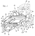
- the embodiment of the device 10 has only one template 52.
- a stop bar 68 or the like is provided parallel to the pressure device 40 for the additional holding of the object 14 on the support 16.
- a second template 52 with a concave-shaped area 54 is provided, which is likewise on the flat support 16 approximately perpendicular to the area to be generated by a further concave and / or convex area 20 of the flat object 14 extending, ie according to arrows 56, 57 along the support 16, is slidably arranged.
- the two templates are 52 designed to be movable towards and away from one another via corresponding drive devices 58.
- two transport devices 69 are provided for holding, moving and connecting two further essentially rigid lateral housing surfaces 94, 96 which accommodate the housing surface 18 held by the template 52 in its predetermined shape.
- the two transport devices 69 run on the flat support 16 approximately in the direction of the generatrix of the concave and / or convex region 20 of the flat object 14, i.e. in the direction of the double arrow 46, slidably arranged.
- the displacement on the flat support 16 takes place via a drive device 70, which is assigned to each of the two transport devices 69.
- the drive devices 70 are in turn connected to the control unit 28 for the displacement of the transport devices 69 approximately in the direction of the generatrix of the concave and / or convex region 20 and can be actuated by the control unit 28.
- a vacuum device 71 or the like, for example, which is not described in detail, can be provided on the two transport devices 69 in order to hold the two further essentially rigid, lateral housing surfaces 94, 96, which receive the housing surface 18 held by the template 52 in its predetermined shape .
- the vacuum device 71 which is connected to and actuated by the control unit 28, thus holds the two housing surfaces 94, 96 for the predetermined time by means of suction lines, to which a vacuum is applied.
- the time largely depends on the time required to move the transport devices 69 after the two housing surfaces 94, 96 have been fitted toward the template or templates 52 in the direction of the generatrix of the concave and / or convex region 20 ' and the tongue and groove or the like Bring the connection between the housing surface 18 and the two housing surfaces 94, 98 into place.
- the negative pressure applied in the suction lines of the vacuum device 71 is switched off, so that the two transport devices 69 can be pushed away from the template or templates 52 in the direction of the generatrices of the concave and / or convex-shaped region 20 'and into their starting position, to again accommodate two housing surfaces 94, 96 for the next housing surface 18 to be molded.
- the heating device 44 and the cooling device 66 according to the embodiment of the device according to FIG. 1 can be dispensed with.
- no pressure device 40 is provided in the exemplary embodiment of the device 10 according to FIG. 2.
- the two embodiments of the devices 10 according to the invention as shown in FIGS. 1 and 2 largely correspond, so that the same components are provided with the same reference numerals.
- the support 16 has transport devices for transporting the flat object 14 from a previous processing station or for transporting the concave and / or convex-shaped housing surface 18 to and from a subsequent processing station.
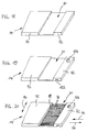
- the essentially flat object 14 which is shown in particular in FIGS. 3 to 9 and preferably consists of thermally softenable or fusible material such as plastic, subsequently forms a housing surface 18 with a concave and / or convex region 20 of a housing 12. 3, 5, 7 and 9, the flat object 14 has, in particular in the concave and / or convex-shaped or shaped region 20 or 20 'of the housing surface 18, a smaller material thickness 73 than in FIG remaining area 72. 8 is the material thickness 73 of the flat object 14 from the at least one housing surface 18 in the concave and / or convex region 20, in particular approximately between 10 and 40%, preferably approximately 25%, of the material thickness 74 of the flat object 14 in the remaining region 72.
- the essentially flat object 14 is provided in advance or the at least one housing surface 18 subsequently in the concave and / or convex region 20 with grooves 76 or the like.
- the grooves 76 or the like run approximately parallel to one another and approximately perpendicular to the generatrix according to the double arrow 46 of the concave and / or convex region 20, i.e. 1 along the support 16 according to the arrows 56, 57 and also the double arrow 34.
- the generatrix itself of the concave and / or convexly shaped or shaped region 20, 20 'of the flat object 14 or the housing surface 18 is so far in Figs. 3, 5 and 7 perpendicular to the sheet plane.
- the grooves 76 or similar recesses all have a depth of approximately 0.05 mm to approximately 0.5 mm, in particular 0.3 mm.
- the grooves 76 or the like recesses are formed essentially continuously.
- grooves 76 or similar recesses are provided which are designed to be interrupted. All grooves 76 or the like recesses are interrupted in this respect by webs 78 or the like, which run approximately in the direction of the generatrix according to double arrow 46 of the concave and / or convex area 20.
- At least part of the grooves 76 or the like is recesses of webs 80 or the like interrupted, which also run approximately in the direction of the generatrix according to double arrow 46 of the concave and / or convex region 20 to be shaped.
- the grooves 76 or similar recesses are therefore made in the flat object 14 from the top side 82 thereof.
- the flat object 14 lies on the support 16 and partially on the inside 86 of the template 52.
- the grooves 76 or the like recesses are additionally straightened at the ends, approximately in the direction of the generatrix according to the double arrow 46 of the region 20 to be shaped concave and / or convex. Such straightening can be carried out, for example reach the two grooves 88 running perpendicular to the grooves 76.
- the template 52 is formed from a multiplicity of approximately disk-like shaped elements 90 which are combined and held together in a block-like manner via screw connections 92 or the like. Apart from a simple production of such individual shaped elements 90, especially by self-construction, the template 52 can thus be advantageously made without any effort, i.e. in their shape and / or width.
- the shape of the concave-shaped area 54 of the template 52 which essentially represents the negative, corresponds essentially to the concave and / or convex area 20 of the object 14, which essentially represents the positive, and vice versa.
- the template 52 is, however, provided with a slight bending in the concave region 54.
- the overbend is an angle of about 3 °.
- FIGS. 10 and 11 An embodiment of a housing 12 produced according to the invention is shown in FIGS. 10 and 11.
- the housing 12 has a housing surface 18 which is substantially completely concave, i.e. is rounded or arched inwards.
- the housing surface 18 thus has a concavely shaped region 20 'which has turned out to be relatively large.
- the housing 12 comprises two further housing surfaces 94, 96, which are essentially rigid and receive the housing surface 18.
- the housing surface 18 and the two further, rigid housing surfaces 94, 96 can be connected to one another by means of a tongue and groove or similar connection 98, in particular in a snap-in manner.
- the further housing surfaces 100, 102 and the housing surfaces (not shown) forming the rear and the underside can also be fastened to the two further rigid housing surfaces 94, 96 and, if appropriate, to the housing surface 18 by means of tongue and groove connections 98 of this type be.
- the at least one housing surface 18 is over the inside 104 of the housing surface 18, i.e. Can be attached to the front via at least one of the two further housing surfaces 94, 96 via the former top side 82 of the flat object 14, by means of the tongue and groove connection 98.
- 13 is designed such that the outside 108 of the at least one housing surface 18 is flush with the end faces 110 of the two further housing surfaces 94, 96.
- the tongue-and-groove or similar connection 98 is designed such that the outside 108 of the at least one housing surface 18 is arranged offset with respect to the end faces 110 of the two further housing surfaces 94, 96.
- FIG. 15 shows a further exemplary embodiment of a housing 12 according to the invention, the at least one housing surface 18 of which has convexly shaped regions 20 ′ or outward-directed curves or arches.
- the edges 112 of the housing 12 according to FIG. 15 are all rounded off.
- the housing surface 18 is connected to a further housing surface 114 with a likewise convexly shaped region 20 on the one hand via tongue and groove or similar connections 98.
- there are two lateral, essentially rigid housing surfaces 94, 96 in FIG. 15, only the housing surface 94 is shown due to the view), of which the two housing surfaces 18, 114 by means of tongue and groove connections (not shown) or similar latching means. or snap connections are added, the additional stabilization.
- the region 20 'of the housing surface 18 which is convex in shape here is at the same time suitable for the latch-like reception of one or more support elements 116 which, in addition to stabilizing the convex region 20', can be provided for receiving boards or the like .
- the circuit board 118 can be attached, for example, to the one or more support elements 116 via a snap-in, snap-in or other plug-in connection.
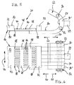
- the spring-back angle ⁇ F is approximately 3 °, by which the previously flat object 14 in the template 52 is bent over, as in dashed lines. After cooling or deformation, the flat object 14 strives to return this springback angle ⁇ F to its original starting position.
- the housing surface 18 thus receives the one in FIG. 15 and 16 shown outer contour in the concave and / or convex shaped area 20 '.
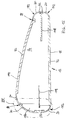
- a formerly flat object 14 is shown, which forms a housing surface 18 with a single, large-area convex area, i.e. an outward curve or bulge is formed.
- the object shown in FIG. 17 is, so to speak, a tube or hollow cylindrical body in which the two facing end faces 120 can be connected to one another by means of a tongue and groove or similar connection 98, in particular in a snap-in manner.
- the essentially flat object 14 is first conveyed up to a substantially flat support 16 by means of a transport device, not shown, and positioned on the support 16.
- the object 14 is placed on the support 16 by a, in particular mechanically, electrically, pneumatically or hydraulically movable, positioning device 24 (cf. FIG. 1) and positioned by means of laser radiation, the current actual position being Position of the object 14 measured via a CO2 laser device, HeNe laser device or the like laser device 36, fed to a control unit 28 for comparison with the predetermined target position and, if necessary, corrected by the positioning device 24.
- the object 14 is then optionally pressed onto the support 16 by a pressure device 40 (cf. also FIG. 1) and thus detachably fixed, preferably laterally slightly spaced from the concave and / or convex region 20 of the object 14.
- the flat object 14 is then essentially to form a housing surface 18 with a concave and / or convex shaped area 20 'or an inward and / or outward curve, curvature etc. by reducing the material thickness 73 made concave and / or convex area 20 deformable.
- the material thickness 73 of the flat object 14 from the at least one housing surface 18 in the concave and / or convex region 20 is approximately between 10 to 40%, in particular approximately 25%, of the material thickness 74 of the flat object 14 in the remaining region 72, preferably reduced by milling.
- the flat object 14 is then mechanically processed in accordance with FIG. 19 in the region 20 to be shaped concavely and / or convex and / or in the remaining region 72, for example provided with a sawn groove 122 or bore 124 etc.
- Mechanical processing can, however, be carried out without further notice before the reduction in the material thickness 73 in the region 20 of the object 14 to be shaped concavely and / or convexly, and at a later point in time.
- the at least one flat object 14 is then made essentially deformable in the concave and / or convex region 20 by grooves 76 or similar recesses which are incorporated into the flat object 14.
- the grooves 76 or the like recesses are additionally introduced after the material thickness 73 has been reduced in the concave and / or convex region 20.
- the grooves 76 or the like recesses are milled approximately parallel to one another and approximately perpendicular to the generatrix of the concave and / or convex region 20 that extends in accordance with the double arrow 46, ie in the direction of the arrows 56, 57, in the planar object 14.
- the grooves 76 or similar recesses are formed essentially continuously or alternatively interrupted. If necessary, at least some of the grooves 76 or the like recesses are interrupted by webs 80 or the like which run approximately in the direction of the generatrix according to the double arrow 46 of the region 20 to be shaped concave and / or convex.
- the grooves 76 or similar recesses are preferably provided on that side of the at least one flat object 14 in the concave and / or convex region 20 which corresponds to the inside 104 of the housing surface 18.
- Grooves 76 or similar recesses have proven to be particularly advantageous for sufficient bendability and at the same time high dimensional stability, which are introduced into the flat object 14 with a depth of approximately 0.05 mm to approximately 0.5 mm, in particular 0.3 mm are.
- the grooves 76 or similar recesses are preferably machined by milling the flat object 14 essentially in the concave and / or convex region 20 of the at least one housing surface 18.
- the grooves 76 or similar recesses are formed with a milling cutter which is guided in an approximately meandering manner through the region 20 to be shaped concavely and / or convexly, the feed speed of the milling cutter being approximately perpendicular in one direction to the generator, for example according to arrow 56, is lower than the feed speed of the milling cutter in the other opposite direction approximately perpendicular to the generator, for example according to arrow 57, as indicated in FIG. 20.
- grooves 76 or the like recesses with an end mill 126, side milling cutter or the like.
- 21 shows a preferred end mill 126, the end face 128 of which only protrudes slightly beyond its central longitudinal axis.
- the grooves 76 or similar recesses are preferably straightened in the direction of the generatrix according to the double arrow 46 of the concave and / or convex area 20 of the object 14 by grooves 88.
- the at least one flat object 14 is then optionally essentially in the concave and / or convex region 20 to be shaped, in particular flat by hot air, which is heated by the heating device 44 which moves back and forth transversely to the support 16 according to double arrow 46.
- the temperature is continuously measured by means of a temperature measuring device 62 and in particular temperature sensors 63. In this way, the required temperature should be set precisely and, in connection therewith, the material of the object 14 should also be protected against overheating.
- the resistance force in the concave and / or convex region 20 of the object 14, which may be softened or melted by the heating device 44, is measured by pressure sensors 65 or the like pressure measuring device 64, which are arranged on the template 52.
- the current actual resistance force is supplied to the control unit 28 for comparison with a predetermined target resistance force.
- two stencils 52 with a concave-shaped region 54 are then provided by a drive device associated with the control unit 28 in the embodiment of the device according to FIG. 23 and also FIG. 2 58 approximately perpendicular to the generatrix of the concave and / or convex region 20 according to arrow 57 (see left template 52) or according to arrow 56 (see right template 52) moved against each other.
- the templates 52 thus move according to the arrows 56, 57 via the respective drive device 58 (not shown here) into the central area of the support 16.
- the flat object 14 therefore rolls, so to speak, in the concave areas 54 of the templates 52.
- the concave and / or convex region 20 of the flat object 14 in the stencils 52 is optionally bent over, preferably by an angle of approximately 3 °.
- the flat object 14 is then held in the template 52 with the concave-shaped area 54 for producing the concave and / or convex area 20 of the housing surface 18.
- the flat object 14 held in the template 52 i.e. the present housing surface 18, at the same time, provided that the concave and / or convex region 20 of the object 14 has previously been heated, in the template 52 itself via a cooling device 66, such as a fan 67 or the like, essentially in a concave and / or convex shaped area 20 'cooled by circulating air, compressed air.
- a cooling device 66 such as a fan 67 or the like, essentially in a concave and / or convex shaped area 20 'cooled by circulating air, compressed air.
- the cooling device 66 moves transversely to the support 16 in accordance with the double arrow 46.
- the tongue and groove or similar connection can be designed in any way. In this way, a housing, cubic body or the like is obtained by the method according to the invention.
- the two further housing surfaces 94, 96 are, for example, mechanically moved laterally in the direction of the generatrix of the two concave and / or convex regions 20 ′ of the housing surface 18 via transport devices 69 (not shown here) in accordance with the double arrow 46 until they engage.
- tubes or other hollow cylindrical or hollow bodies can be produced with the method according to the invention, namely by in each case two mutually facing end faces 120 of the object 14 brought into the predetermined shape by means of a tongue and groove or similar connection 98, in particular snap-in, mutually or be connected to end faces of another object (not shown) brought into the predetermined shape.
- the two stencils 52 with the concave-shaped area 54 are then moved apart approximately vertically to the area 20 to be formed concave and / or convex according to arrow 56 (cf. left template 52) or according to arrow 57 (cf. right template 52) , again by the drive device 58 connected to the control unit 28.
- the deformed object 14 or the housing surface 18 with the concavely and / or convexly shaped region is finally conveyed on to a next processing station via a transport device, not shown.
Landscapes
- Engineering & Computer Science (AREA)
- Mechanical Engineering (AREA)
- Shaping Of Tube Ends By Bending Or Straightening (AREA)
Applications Claiming Priority (2)
| Application Number | Priority Date | Filing Date | Title |
|---|---|---|---|
| DE4308391 | 1993-03-16 | ||
| DE19934308391 DE4308391C2 (de) | 1993-03-16 | 1993-03-16 | Verfahren und Vorrichtung zur Herstellung von Gehäusen oder dergleichen sowie derartige Gehäuse oder dergleichen |
Publications (3)
| Publication Number | Publication Date |
|---|---|
| EP0615831A2 true EP0615831A2 (fr) | 1994-09-21 |
| EP0615831A3 EP0615831A3 (fr) | 1995-05-03 |
| EP0615831B1 EP0615831B1 (fr) | 1998-08-19 |
Family
ID=6482971
Family Applications (1)
| Application Number | Title | Priority Date | Filing Date |
|---|---|---|---|
| EP19940103425 Expired - Lifetime EP0615831B1 (fr) | 1993-03-16 | 1994-03-07 | Procédé et dispositif pour la fabrication de boítiers ou d'objets similaires et boítiers ainsi obtenus |
Country Status (2)
| Country | Link |
|---|---|
| EP (1) | EP0615831B1 (fr) |
| DE (2) | DE4308391C2 (fr) |
Cited By (1)
| Publication number | Priority date | Publication date | Assignee | Title |
|---|---|---|---|---|
| CN114162617A (zh) * | 2021-12-16 | 2022-03-11 | 浙江炬光电子科技有限公司 | 一种应用于打火机压电点火器自动组装设备的出料装置 |
Families Citing this family (1)
| Publication number | Priority date | Publication date | Assignee | Title |
|---|---|---|---|---|
| DE10119673A1 (de) * | 2001-04-20 | 2002-10-24 | Aristo Graphic Systeme | Rillen von biegesteifen Kunststoffplatten auf Bearbeitungsplottern |
Family Cites Families (7)
| Publication number | Priority date | Publication date | Assignee | Title |
|---|---|---|---|---|
| DE1031505B (de) * | 1955-01-20 | 1958-06-04 | Gewerkschaft Philippine | Verfahren zur Biegeverformung von Gegenstaenden aus thermoplastischen Schaumkunststoffen |
| DE1279437B (de) * | 1967-01-19 | 1968-10-03 | Dr Adolf Schauer | Schneidevorrichtung fuer eine Maschine zum Herstellen von spiralfoermigen Stuecken aus duennem, verformbarem Material |
| GB1362242A (en) * | 1972-08-14 | 1974-07-30 | Smith & Nephew Res | Plastics hinge |
| DE3516862A1 (de) * | 1985-05-10 | 1986-11-13 | Resopal Werk H. Römmler GmbH, 6800 Mannheim | Verfahren zur herstellung von bauelementen |
| DE8611965U1 (de) * | 1986-04-30 | 1986-08-21 | La Tolerie Plastique, Le Havre | Gehäuse |
| NL8700898A (nl) * | 1987-04-15 | 1988-11-01 | Ploeg Lunteren Bv | Werkwijze voor het buigen van een massieve plaat uit een hogedruk laminaat van fenolhars en volgens de werkwijze gebogen plaat. |
| IT225029Z2 (it) * | 1991-08-08 | 1996-09-18 | Berloni Mobili Spa | Foglio laminato plastico per il rivestimento di piani autoportanti dotato di zone di spessore assotigliato |
-
1993
- 1993-03-16 DE DE19934308391 patent/DE4308391C2/de not_active Expired - Fee Related
-
1994
- 1994-03-07 EP EP19940103425 patent/EP0615831B1/fr not_active Expired - Lifetime
- 1994-03-07 DE DE59406705T patent/DE59406705D1/de not_active Expired - Fee Related
Cited By (1)
| Publication number | Priority date | Publication date | Assignee | Title |
|---|---|---|---|---|
| CN114162617A (zh) * | 2021-12-16 | 2022-03-11 | 浙江炬光电子科技有限公司 | 一种应用于打火机压电点火器自动组装设备的出料装置 |
Also Published As
| Publication number | Publication date |
|---|---|
| EP0615831A3 (fr) | 1995-05-03 |
| EP0615831B1 (fr) | 1998-08-19 |
| DE4308391C2 (de) | 1996-08-14 |
| DE59406705D1 (de) | 1998-09-24 |
| DE4308391A1 (de) | 1994-09-22 |
Similar Documents
| Publication | Publication Date | Title |
|---|---|---|
| EP0456121B1 (fr) | Procédé pour le pliage d'objets plats ainsi que la machine de pliage pour la mise en oeuvre du procédé | |
| EP0594096A1 (fr) | Procédé et dispositif pour déformer, notamment pour plier des objets essentiellement plats | |
| DE102006040893B3 (de) | Verfahren zur Herstellung eines Blechbauteils für Kraftfahrzeuge | |
| EP2594355B1 (fr) | Machine et méthode de coupage et de soudage avec un dispositif de positionnement de deux extrémités de matériaux l'une contre l'autre | |
| EP3655235B1 (fr) | Procédé de préparation additive et système d'unité de substrat | |
| DE102016102240A1 (de) | Vorrichtung zum Verbinden von Profilstücken | |
| DE102013222242A1 (de) | Anlage zur Herstellung von Bauteilen mit Warmumformung und Verfahren | |
| DE102007008653A1 (de) | Umformverfahren und Vorrichtung zur Durchführung eines Umformverfahrens | |
| EP1030024A2 (fr) | Procedure et dispositif pour la production d'espaceurs pour vitrage isolant en profilés creux | |
| DE102016125483A1 (de) | Verfahren und Vorrichtung zum Verbinden von Kunststoffprofilteilen | |
| EP0615831B1 (fr) | Procédé et dispositif pour la fabrication de boítiers ou d'objets similaires et boítiers ainsi obtenus | |
| EP3589756B1 (fr) | Procédé de formage d'une tôle et installation de fabrication avec dispositif de chauffage par conduction | |
| DE19801346C1 (de) | Vorrichtung und Verfahren zum Formprägen eines schmelzfähigen Materials | |
| DE69718274T2 (de) | Spritzgiessmaschine und Spritzgiessverfahren zur Dekoration von Schichten | |
| EP1684968A1 (fr) | Procede pour produire une plaque thermoplastique ayant au moins une arete laterale lissee, dispositif correspondant et systeme d'usinage d'arete | |
| AT411162B (de) | Kaliberplatte mit einem einsatzteil für eine formgebungseinrichtung | |
| DE102022002959A1 (de) | Schweißvorrichtung und Verfahren zum Verschweißen zweier Werkstücke | |
| DE102010012359A1 (de) | Vorrichtung zum Verschweißen von Profilteilen | |
| DE69511485T2 (de) | Blattfederbiegemaschine | |
| EP1210998B1 (fr) | Procédé et dispositif pour la fabrication d'un profil métallique | |
| DE69906469T2 (de) | Verfahren zur Erzeugung einer lasttragenden Oberfläche | |
| DE2704999A1 (de) | Verfahren und anlage zur herstellung von bandstahlmessern | |
| DE102008043401B4 (de) | Verfahren und Vorrichtung zur Herstellung von Blechbauteilen mittels Warmumformung sowie dadurch hergestellte Blechbauteile | |
| EP0867417B1 (fr) | Dispositif de moulage pour façonner des structures dans des feuilles de verre | |
| DE19510121C2 (de) | Verfahren zur Herstellung einer gekrümmten Wandung aus einem streifenförmigen Ausgangsmaterial mit parallelen Seitenkanten und parallelen Längskanten |
Legal Events
| Date | Code | Title | Description |
|---|---|---|---|
| PUAI | Public reference made under article 153(3) epc to a published international application that has entered the european phase |
Free format text: ORIGINAL CODE: 0009012 |
|
| AK | Designated contracting states |
Kind code of ref document: A2 Designated state(s): BE DE ES FR GB IT NL PT |
|
| PUAL | Search report despatched |
Free format text: ORIGINAL CODE: 0009013 |
|
| AK | Designated contracting states |
Kind code of ref document: A3 Designated state(s): BE DE ES FR GB IT NL PT |
|
| 17P | Request for examination filed |
Effective date: 19951102 |
|
| GRAG | Despatch of communication of intention to grant |
Free format text: ORIGINAL CODE: EPIDOS AGRA |
|
| 17Q | First examination report despatched |
Effective date: 19971007 |
|
| GRAG | Despatch of communication of intention to grant |
Free format text: ORIGINAL CODE: EPIDOS AGRA |
|
| GRAG | Despatch of communication of intention to grant |
Free format text: ORIGINAL CODE: EPIDOS AGRA |
|
| GRAH | Despatch of communication of intention to grant a patent |
Free format text: ORIGINAL CODE: EPIDOS IGRA |
|
| GRAH | Despatch of communication of intention to grant a patent |
Free format text: ORIGINAL CODE: EPIDOS IGRA |
|
| GRAA | (expected) grant |
Free format text: ORIGINAL CODE: 0009210 |
|
| AK | Designated contracting states |
Kind code of ref document: B1 Designated state(s): BE DE ES FR GB IT NL PT |
|
| PG25 | Lapsed in a contracting state [announced via postgrant information from national office to epo] |
Ref country code: NL Free format text: LAPSE BECAUSE OF FAILURE TO SUBMIT A TRANSLATION OF THE DESCRIPTION OR TO PAY THE FEE WITHIN THE PRESCRIBED TIME-LIMIT Effective date: 19980819 Ref country code: IT Free format text: LAPSE BECAUSE OF FAILURE TO SUBMIT A TRANSLATION OF THE DESCRIPTION OR TO PAY THE FEE WITHIN THE PRE;WARNING: LAPSES OF ITALIAN PATENTS WITH EFFECTIVE DATE BEFORE 2007 MAY HAVE OCCURRED AT ANY TIME BEFORE 2007. THE CORRECT EFFECTIVE DATE MAY BE DIFFERENT FROM THE ONE RECORDED.SCRIBED TIME-LIMIT Effective date: 19980819 Ref country code: GB Free format text: LAPSE BECAUSE OF FAILURE TO SUBMIT A TRANSLATION OF THE DESCRIPTION OR TO PAY THE FEE WITHIN THE PRESCRIBED TIME-LIMIT Effective date: 19980819 Ref country code: FR Free format text: LAPSE BECAUSE OF FAILURE TO SUBMIT A TRANSLATION OF THE DESCRIPTION OR TO PAY THE FEE WITHIN THE PRESCRIBED TIME-LIMIT Effective date: 19980819 Ref country code: ES Free format text: THE PATENT HAS BEEN ANNULLED BY A DECISION OF A NATIONAL AUTHORITY Effective date: 19980819 |
|
| REF | Corresponds to: |
Ref document number: 59406705 Country of ref document: DE Date of ref document: 19980924 |
|
| PG25 | Lapsed in a contracting state [announced via postgrant information from national office to epo] |
Ref country code: PT Free format text: LAPSE BECAUSE OF FAILURE TO SUBMIT A TRANSLATION OF THE DESCRIPTION OR TO PAY THE FEE WITHIN THE PRESCRIBED TIME-LIMIT Effective date: 19981119 |
|
| EN | Fr: translation not filed | ||
| NLV1 | Nl: lapsed or annulled due to failure to fulfill the requirements of art. 29p and 29m of the patents act | ||
| GBV | Gb: ep patent (uk) treated as always having been void in accordance with gb section 77(7)/1977 [no translation filed] |
Effective date: 19980819 |
|
| PG25 | Lapsed in a contracting state [announced via postgrant information from national office to epo] |
Ref country code: BE Free format text: LAPSE BECAUSE OF NON-PAYMENT OF DUE FEES Effective date: 19990331 |
|
| PLBE | No opposition filed within time limit |
Free format text: ORIGINAL CODE: 0009261 |
|
| STAA | Information on the status of an ep patent application or granted ep patent |
Free format text: STATUS: NO OPPOSITION FILED WITHIN TIME LIMIT |
|
| 26N | No opposition filed | ||
| BERE | Be: lapsed |
Owner name: T.T.K. KUNSTSTOFF-TECHNOLOGIE G.M.B.H. Effective date: 19990331 |
|
| PG25 | Lapsed in a contracting state [announced via postgrant information from national office to epo] |
Ref country code: DE Free format text: LAPSE BECAUSE OF NON-PAYMENT OF DUE FEES Effective date: 20000101 |