EP0615873A2 - Disposition d'étanchéité - Google Patents
Disposition d'étanchéité Download PDFInfo
- Publication number
- EP0615873A2 EP0615873A2 EP94103801A EP94103801A EP0615873A2 EP 0615873 A2 EP0615873 A2 EP 0615873A2 EP 94103801 A EP94103801 A EP 94103801A EP 94103801 A EP94103801 A EP 94103801A EP 0615873 A2 EP0615873 A2 EP 0615873A2
- Authority
- EP
- European Patent Office
- Prior art keywords
- edge
- glass plate
- sealing arrangement
- arrangement according
- clamping area
- Prior art date
- Legal status (The legal status is an assumption and is not a legal conclusion. Google has not performed a legal analysis and makes no representation as to the accuracy of the status listed.)
- Granted
Links
Images

Classifications
-
- B—PERFORMING OPERATIONS; TRANSPORTING
- B60—VEHICLES IN GENERAL
- B60J—WINDOWS, WINDSCREENS, NON-FIXED ROOFS, DOORS, OR SIMILAR DEVICES FOR VEHICLES; REMOVABLE EXTERNAL PROTECTIVE COVERINGS SPECIALLY ADAPTED FOR VEHICLES
- B60J10/00—Sealing arrangements
- B60J10/80—Sealing arrangements specially adapted for opening panels, e.g. doors
- B60J10/82—Sealing arrangements specially adapted for opening panels, e.g. doors for movable panels in roofs
Definitions
- the invention relates to a sealing arrangement for the gap between the rigid cover of a vehicle roof and the roof opening, in which the cover is glued from a glass plate with a base frame that is placed underneath and protrudes laterally, and between the glass plate circumference and roof opening, a gap seal with the protruding edge of the Basic frame is connected.
- Such a cover is known from DE-OS 36 39 894.
- This cover consists of a large number of individual parts that have to be put together during the final assembly.
- a circumferential T-shaped aluminum profile is placed between the glass plate and the actual seal, which must also be anchored against the protruding edge of the base frame. Overall, several operations and tools are required to create a finished lid.
- the present invention is based on the object of creating a sealing arrangement for such a cover, with which such a cover can be manufactured much more easily and in particular can be assembled from fewer individual parts.
- the gap seal has a U-shaped, armored clamping area made of an elastomer with a lip-shaped extension overlapping the edge of the glass plate and a sealing lip directed against the peripheral edge of the glass plate on one side of the clamping area and has on the other side extruded hollow chamber profile made of foam rubber and that the gap seal with its U-shaped clamping area is clamped onto a bent edge of the base frame.
- the gap seal which surrounds the glass plate and the base frame, can consist of a profile section A which extends over the front edge of the cover and has a sealing lip which projects laterally from the foam rubber profile to the roof opening, and a profile section B which extends over the other peripheral areas of the cover and one with a section bordering the foam rubber profile Legs of the U-shaped clamping area are perpendicular protruding sealing web, the two profile sections are permanently connected at their abutments to form a one-piece frame.
- the elastomer part of the gap seal expediently consists of EPDM with a Shore A hardness of approximately 70.
- the reinforcement of the U-shaped clamping area can consist of a vulcanized-in punched strip with incisions on the edge.
- the lip-shaped attachment has a stiffening in the form of an aluminum strip or punched strip, which extends above the U-shaped reinforcement.
- the U-shaped clamping area has on its leg on the glass plate side a horizontal extension directed towards the glass plate, into which an angled end of the reinforcement extends.
- the glass plate and base frame can be connected by means of an adhesive layer in such a way that the free end of the attachment is also embedded in the adhesive layer.
- sealing lip directed against the edge of the glass plate is designed as a triangular sealing hollow chamber with an indentation notch in the horizontal leg.
- the U-shaped clamping area can have a plurality of obliquely protruding clamping lips on its inside.
- the raised edge has a lateral bulge, which engages on one side in a corresponding recess of the one U-leg and the other U-leg is provided with a similar bulge, which in the through the bulge engaging rear recess of the edge.
- U-shaped clamping area is connected to the raised edge by means of an activatable adhesive.
- Such an activatable adhesive layer expediently has an internal, current-carrying copper strand for heating and activating the adhesive.
- the activatable adhesive is expediently applied to an inside of the U-shaped clamping area, in particular extruded and after being pushed on pressed and activated the clamping area on the bent edge.
- the cover which essentially consists of a glass plate 2 is enclosed on all sides by a gap seal 3 towards the roof opening 1.
- the gap seal 3 consists of two different profile sections, namely the profile section A on the front edge of the lid to be opened and the profile section B, which encloses the other areas of the lid 2.
- the profile section A to the profile section B has two joints 4 and 5, at which the profile sections A and B are glued together to form a closed frame.
- the glass plate 2 shows a longitudinal section through the edge region of the cover corresponding to the section line II-II according to FIG. 1. Thereafter, the glass plate 2 is first connected to a base frame 10, which is placed underneath and protrudes laterally in the edge region, by means of an interposed adhesive 11.
- the base frame 10 has on the outer circumference a raised edge 12 on which the gap seal 3 of the profile area A is pushed on, this gap seal 3 being constructed in detail as follows.
- the seal initially has a U-shaped clamping area 13 made of an elastomer, this elastomer e.g. can be made of EPDM with a Shore A hardness of about 70.
- This clamping area 13 is provided with a likewise U-shaped reinforcement 14 in the form of a vulcanized-in punched strip with incisions on the edge. From the top of this clamping area 13 protrudes toward the glass plate 2 towards a lip-shaped extension 15, which covers the edge of the glass plate 2 and is also provided with a stiffener 16 in the form of an aluminum strip or punched strip, this stiffening 16 extending beyond the reinforcement 14 of the Clamping area 13 extends.
- a sealing lip 17 protruding from the clamping area 13 to the peripheral edge of the glass plate 2 is provided, which essentially also effects a tolerance compensation to the glass plate 2. Furthermore, from the lower end of the leg of the clamping area 13 on the glass plate side, an extension 18 directed towards the glass plate 2 extends, into which an angled end 19 of the reinforcement 14 extends.
- a hollow chamber profile 20 made of foam rubber is extruded onto the clamping area 13, which is provided on its top and front with flocking 21 for sealing and better sliding with respect to the roof cutout 1.
- Fig. 3 shows a longitudinal section through the profile areas B on the other sides of the glass plate 2.
- the seal 3 differs from the profile area A shown in Fig. 2 only in that the outer leg of the clamping area 13 has a vertically projecting sealing web 25 and one likewise downwardly projecting sealing lip 23 from the foam rubber area 20, which corresponds to the sealing lip 22 according to FIG. 2 projecting towards the roof cutout 1.
- the two profile sections A and B are now glued together at their joints 4 and 5 and pushed onto the upstanding edge 12 of the base frame 10 as a closed frame.
- the adhesive 11 is heated so that the protruding projections 18 of the clamping area 13 are embedded in the adhesive 11 and are thus additionally anchored.
- the U-shaped clamping area 13 has a plurality of obliquely protruding clamping lips 30 on its inside, which are directed against the withdrawal direction from the edge 12 and thus prevent the profile from being pulled out.
- FIGS. 4 to 6 Further clamping options are shown in FIGS. 4 to 6. 4, a U-shaped bracket 31 is placed on the bent edge 12, which has outwardly bent ends 32, which in corresponding Recesses 33 protrude on the inside of the U-shaped clamping area 13. The clips 31 can be firmly connected to the edge 12, so that a firm locking of the gap seal is possible.
- a somewhat differently designed clip 35 is pushed onto the bent edge 12.
- the clamp 35 likewise has outwardly projecting ends 36 which protrude into corresponding recesses 37 in the U-shaped clamping region 13.
- the raised edge still has indentations 38, into which correspondingly retracted areas 39 of the clamp 35 snap. This also ensures secure anchoring.
- FIG. 6 Another possibility is shown in FIG. 6. Thereafter, the raised edge 12 has a lateral bulge 40, the bulged side engaging in a corresponding recess 41 on one U-leg of the clamping area 13, while the other U-leg has a similar bulge 42, which in the corresponding recess of the Bulge 40 engages. This also ensures a secure locking of the gap seal.
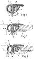
- FIGS. 7 to 9. 7 shows a cross section through this gap seal for the profile area B.
- a U-shaped clamping area 50 with a downwardly projecting projection 51 is also provided on one leg of the clamping area.
- the other leg 52 has a triangular sealing hollow chamber 53, in the horizontal leg of which an indentation notch 54 is provided.
- this triangular sealing hollow chamber 53 seals against the circumferential edge of the glass plate 2 and here offers a tolerance compensation for the gap seal and the glass pane 2 through the indentation notch 54.
- an activatable adhesive 55 is applied or extruded onto the inside of the outer leg of the U-shaped clamping area 50.
- Such an activatable adhesive 55 consists, for example, of a PU granulate, in the interior of which, for example, a copper wire 56 connected to a power source is embedded.
- a copper wire 56 connected to a power source is embedded.
- the activatable adhesive 55 is initially somewhat compressed after the gap seal 3 has been pushed onto the bent edge 12 of the frame 10 and, after its activation, forms a firm connection between the U-shaped clamping area 50 and the bent edge 12 of the frame 10.
- Fig. 9 shows a longitudinal section through this gap seal 3 in the region of the profile section A at the front edge of the roof opening, the profile here only differing from the profile region B in that the vertical extension 51 according to FIG. 8 is absent and the foam rubber region 56 is inclined downwardly projecting sealing lip 57 is provided for roof cutout 1.
Landscapes
- Engineering & Computer Science (AREA)
- Mechanical Engineering (AREA)
- Seal Device For Vehicle (AREA)
- Sealing Battery Cases Or Jackets (AREA)
- Glass Compositions (AREA)
- Materials For Medical Uses (AREA)
- Packages (AREA)
Applications Claiming Priority (2)
| Application Number | Priority Date | Filing Date | Title |
|---|---|---|---|
| DE4308218 | 1993-03-15 | ||
| DE4308218A DE4308218C2 (de) | 1993-03-15 | 1993-03-15 | Dichtungsanordnung |
Publications (3)
| Publication Number | Publication Date |
|---|---|
| EP0615873A2 true EP0615873A2 (fr) | 1994-09-21 |
| EP0615873A3 EP0615873A3 (fr) | 1995-02-01 |
| EP0615873B1 EP0615873B1 (fr) | 1999-10-13 |
Family
ID=6482857
Family Applications (1)
| Application Number | Title | Priority Date | Filing Date |
|---|---|---|---|
| EP94103801A Expired - Lifetime EP0615873B1 (fr) | 1993-03-15 | 1994-03-11 | Disposition d'étanchéité |
Country Status (5)
| Country | Link |
|---|---|
| US (1) | US5538317A (fr) |
| EP (1) | EP0615873B1 (fr) |
| JP (1) | JP2757296B2 (fr) |
| AT (1) | ATE185523T1 (fr) |
| DE (2) | DE4308218C2 (fr) |
Families Citing this family (34)
| Publication number | Priority date | Publication date | Assignee | Title |
|---|---|---|---|---|
| DE69608444T2 (de) * | 1995-08-25 | 2001-02-08 | Draftex Industries Ltd., Edinburgh | Dichtungs- und führungsstreifen |
| JPH09123769A (ja) * | 1995-10-30 | 1997-05-13 | Toyota Autom Loom Works Ltd | 樹脂製スライドウインド |
| DE19754402B4 (de) * | 1997-12-09 | 2007-03-15 | Webasto Ag | Zweiteilige Dichtung an einem Deckel eines öffnungsfähigen Fahrzeugdachs |
| DE19754403C1 (de) * | 1997-12-09 | 1999-01-07 | Webasto Systemkomponenten Gmbh | Transparenter Deckel eines öffnungsfähigen Fahrzeugdachs |
| JP2000296718A (ja) * | 1999-04-14 | 2000-10-24 | Toyota Autom Loom Works Ltd | スライディングルーフのウエザーストリップ取り付け構造 |
| DE19921233C2 (de) * | 1999-05-07 | 2001-06-28 | Metzeler Automotive Profiles | Dichtungsanordnung zum Abdichten eines Schließteils |
| DE10005642B4 (de) * | 2000-02-09 | 2004-04-29 | Metzeler Automotive Profile Systems Gmbh | Randspaltdichtung |
| JP2001301470A (ja) * | 2000-04-21 | 2001-10-31 | Toyoda Gosei Co Ltd | サンルーフ用ガラスリッド外周のシール構造 |
| JP4284828B2 (ja) * | 2000-04-28 | 2009-06-24 | 株式会社豊田自動織機 | 車両の透光パネル取り付け構造 |
| JP4113999B2 (ja) * | 2000-04-28 | 2008-07-09 | 株式会社豊田自動織機 | 車両における透光パネル取付構造及び透光パネル組み付け方法 |
| DE10035912C2 (de) * | 2000-07-21 | 2003-05-15 | Webasto Vehicle Sys Int Gmbh | Kunststoffdeckel für Fahrzeuge |
| DE10042439B4 (de) * | 2000-08-30 | 2004-07-08 | Bayerische Motoren Werke Ag | Tragflansch eines Kraftfahrzeugs für eine aufsteckbare Dichtung |
| DE10043136B4 (de) * | 2000-08-31 | 2013-08-01 | Webasto Ag | Dichtungsprofil, insbesondere für eine Schiebedachdichtung |
| DE10122637B4 (de) * | 2001-03-16 | 2005-07-21 | Wagon Automotive Gmbh | Dichtungsanordnung für eine Kraftfahrzeugtüre und/oder ein Kraftfahrzeugfenster |
| JP3704645B2 (ja) * | 2002-03-20 | 2005-10-12 | 西川ゴム工業株式会社 | サンルーフ用ウエザーストリップ |
| US6814813B2 (en) * | 2002-04-24 | 2004-11-09 | Micron Technology, Inc. | Chemical vapor deposition apparatus |
| DE102004003566B4 (de) * | 2003-01-31 | 2005-09-15 | Toyoda Gosei Co., Ltd. | Befestigungsstruktur für einen Dichtungsstreifen für ein Kraftfahrzeug |
| US20050161886A1 (en) * | 2004-01-28 | 2005-07-28 | Berry David H. | Heat-activated expandable seal and method for producing same |
| GB2432870A (en) * | 2005-11-18 | 2007-06-06 | Gdx North America Inc | Sealing assemblies and methods of making them |
| US8516749B2 (en) * | 2008-02-20 | 2013-08-27 | Pilkington Group Limited | Encapsulated window assembly with integral seal and method of installing game |
| US9580954B2 (en) | 2009-10-05 | 2017-02-28 | R Value, Inc. | Press fit storm window system |
| US9255438B2 (en) | 2009-10-05 | 2016-02-09 | R Value, Inc. | Press fit storm window system |
| US10202796B2 (en) | 2009-10-05 | 2019-02-12 | R Value, Inc. | Press fit storm window system |
| CA2806334A1 (fr) | 2010-07-28 | 2012-02-02 | Press-Seal Gasket Corporation | Joint d'etancheite de porte de remorque |
| DE202011000804U1 (de) * | 2011-04-06 | 2012-07-09 | Richard Fritz Gmbh + Co. Kg | Scheibeneinheit für Fenster an Kraftfahrzeugen |
| US9227499B2 (en) | 2011-09-15 | 2016-01-05 | Henniges Automotive Sealing Systems North America Inc. | Weatherstrip assembly having a removable retaining member |
| DE102012023043A1 (de) * | 2012-05-10 | 2013-11-14 | GM Global Technology Operations LLC (n. d. Gesetzen des Staates Delaware) | Dichtleiste für ein Kraftfahrzeug, insbesondere Fensterschachtdichtleiste |
| DE102012106340B4 (de) | 2012-07-13 | 2022-07-14 | Bayerische Motoren Werke Aktiengesellschaft | Dichtungsstrang zur Verklebung mit einer Fahrzeugkarosserie |
| US9032668B2 (en) | 2012-09-07 | 2015-05-19 | Press-Seal Gasket Corporation | Seal with primary and secondary sealing lobes for use in roll-up door applications |
| CA2881683C (fr) * | 2012-09-17 | 2018-07-24 | Steelcase Inc. | Ensemble de mur de separation du plafond au plancher |
| US9151107B2 (en) | 2013-09-24 | 2015-10-06 | Press-Seal Gasket Corporation | Trailer door seal |
| CN106061779B (zh) * | 2014-02-07 | 2018-01-23 | 瀚德汽车密封系统北美有限公司 | 车辆密封组件及其制造方法 |
| DE102017207344A1 (de) * | 2017-05-02 | 2018-11-08 | Skf Marine Gmbh | Abdeckvorrichtung sowie Strahlruder |
| DE102021117708B3 (de) * | 2021-07-08 | 2022-08-25 | Webasto SE | Öffenbares Fahrzeugdach mit Dachausschnitt und Dichtungsanordnung |
Family Cites Families (19)
| Publication number | Priority date | Publication date | Assignee | Title |
|---|---|---|---|---|
| US2772915A (en) * | 1954-06-01 | 1956-12-04 | Motor Products Corp | Window assembly for vehicle bodies |
| US3171886A (en) * | 1960-12-12 | 1965-03-02 | Hall C M Lamp Co | Mirror retaining means and method of assembly |
| GB1378615A (en) * | 1973-03-19 | 1974-12-27 | Avon Rubber Co Ltd | Sealing strips |
| DE7912486U1 (de) * | 1979-04-28 | 1979-08-09 | Webasto-Werk W. Baier Gmbh & Co, 8031 Stockdorf | Deckelinnenblech für Glasdeckel |
| DE3134340C2 (de) * | 1981-08-31 | 1983-09-29 | Vereinigte Glaswerke Gmbh, 5100 Aachen | Einklebbare Fahrzeug-Glasscheibe |
| US4610907A (en) * | 1983-05-05 | 1986-09-09 | Elastomeros Riojanos S.A. | Metal core of sections for automobile and similar vehicles |
| JPS60148719A (ja) * | 1984-01-13 | 1985-08-06 | Kinugawa Rubber Ind Co Ltd | サンル−フ用ウエザ−ストリツプ |
| GB2181698B (en) * | 1985-10-17 | 1990-01-24 | Draftex Ind Ltd | Reinforcing carriers for trimming and sealing strips and the like |
| NL8503254A (nl) * | 1985-11-26 | 1986-06-02 | Vermeulen Hollandia Octrooien | Elastische afdichting voor een verplaatsbaar paneel van een open dakconstructie voor een voertuig. |
| DE3619268C1 (en) * | 1986-06-07 | 1987-10-01 | Rockwell Golde Gmbh | Rigid cover plate for car sliding roof - has support frame with clamping rail, spaced parallel to frame upper edge and laterally resilient |
| DE3639894A1 (de) * | 1986-11-21 | 1988-06-01 | Rockwell Golde Gmbh | Starrer deckel fuer ein fahrzeugdach |
| EP0330771A1 (fr) * | 1988-03-01 | 1989-09-06 | Tudor Webasto Limited | Dispositif d'étanchéité pour une ouverture |
| DE3940304C1 (en) * | 1988-08-26 | 1991-01-24 | Rockwell Golde Gmbh, 6000 Frankfurt, De | Rigid car roof cover - comprises glass or plastics plate with metal U=profile gap compensators having rigid inner and deformable outer legs |
| JPH02115720U (fr) * | 1989-03-06 | 1990-09-17 | ||
| US5310236A (en) * | 1989-10-18 | 1994-05-10 | Hashimoto Forming Industry Co., Ltd. | Molding member for automobile window plate |
| JPH0747371B2 (ja) * | 1990-01-31 | 1995-05-24 | 鬼怒川ゴム工業株式会社 | サンルーフ用ウエザーストリップ |
| JP2607973B2 (ja) * | 1990-09-03 | 1997-05-07 | 豊田合成株式会社 | 自動車用ウエザーストリップ |
| US5170587A (en) * | 1990-09-03 | 1992-12-15 | Toyoda Gosei Co., Ltd. | Weatherstrip for automotive vehicle |
| JPH0490423U (fr) * | 1990-12-20 | 1992-08-06 |
-
1993
- 1993-03-15 DE DE4308218A patent/DE4308218C2/de not_active Expired - Fee Related
-
1994
- 1994-03-11 EP EP94103801A patent/EP0615873B1/fr not_active Expired - Lifetime
- 1994-03-11 AT AT94103801T patent/ATE185523T1/de not_active IP Right Cessation
- 1994-03-11 DE DE59408811T patent/DE59408811D1/de not_active Expired - Fee Related
- 1994-03-14 JP JP6070074A patent/JP2757296B2/ja not_active Expired - Lifetime
-
1995
- 1995-11-13 US US08/557,368 patent/US5538317A/en not_active Expired - Fee Related
Also Published As
| Publication number | Publication date |
|---|---|
| US5538317A (en) | 1996-07-23 |
| DE4308218A1 (de) | 1994-09-22 |
| ATE185523T1 (de) | 1999-10-15 |
| EP0615873B1 (fr) | 1999-10-13 |
| EP0615873A3 (fr) | 1995-02-01 |
| JP2757296B2 (ja) | 1998-05-25 |
| DE59408811D1 (de) | 1999-11-18 |
| DE4308218C2 (de) | 1996-11-07 |
| JPH06297961A (ja) | 1994-10-25 |
Similar Documents
| Publication | Publication Date | Title |
|---|---|---|
| EP0615873A2 (fr) | Disposition d'étanchéité | |
| DE4339033C2 (de) | Anordnung zum gleichzeitigen Abdichten einer Türscheibe und der Türöffnung an einem Kraftfahrzeug | |
| DE4308221C2 (de) | Dichtungsanordnung für einen Deckel an einem Fahrzeugdach | |
| DE69200265T2 (de) | Dichtungszierleiste für das Einfassen einer beweglichen Kraftfahrzeugscheibe. | |
| DE2912403A1 (de) | Halteeinheit fuer eine kantenabdichtung | |
| EP0945296B1 (fr) | Fixation pour enjoliveur destiné à habiller le bord d'un panneau en verre | |
| EP1131220A1 (fr) | Profile d'etancheite pour une fenetre de voiture decapotable | |
| DE19926955B4 (de) | Stegkappe aus gummielastischem Material | |
| EP1406779A1 (fr) | Profile d'etancheite pour fenetres d'une voiture decapotable | |
| DE10038200B4 (de) | Fensterdichtung zur Anbringung an einer Kraftfahrzeugtüre | |
| EP0596306A2 (fr) | Baguette encastrée pour une rainure tracée dans le toit d'un véhicule | |
| DE570520C (de) | Tuer, insbesondere fuer geschlossene Wagenkasten bei Kraftfahrzeugen | |
| EP1033270A2 (fr) | Toit pliant pour véhicule automobile avec un élément de couverture extérieur et un revêtement de toit et avec l'élément de couverture equipé au moins d'un panneau en vitre | |
| DE3140140A1 (de) | "dichtung fuer eine bewegliche angeordnete fensterscheibe" | |
| DE4314123A1 (de) | Tür für ein Kraftfahrzeug | |
| DE102010056385A1 (de) | Fahrzeugtür mit einer Säulenblende | |
| DE29602223U1 (de) | Dichtleiste zum dichtenden Abschließen einer Rinne, beispielsweise in oder an einem Fahrzeugdach | |
| DE202013103871U1 (de) | Abdichtungsprofil zum Anschluss eines Anbauteils an eine Scheibe, sowie Abdichtungsanordnung | |
| DE19531600B4 (de) | Dichtung für eine verlagerbare Fensterscheibe eines Fahrzeugs | |
| DE19715897A1 (de) | Kurbelfenster in einer Fahrzeugtür | |
| DE10050346B4 (de) | Dichtungsanordnung für ein Kraftfahrzeug | |
| DE102019208787B4 (de) | Befestigungsanordnung für eine Fensterschachtleiste | |
| DE19628107C1 (de) | Lösbare Befestigung für eine Heckscheibe in einem Faltverdeck eines Personenkraftwagens | |
| EP0350848A2 (fr) | Procédé pour la fixation d'un guide de vitre | |
| DE29618634U1 (de) | Einfaßprofilelement |
Legal Events
| Date | Code | Title | Description |
|---|---|---|---|
| PUAI | Public reference made under article 153(3) epc to a published international application that has entered the european phase |
Free format text: ORIGINAL CODE: 0009012 |
|
| AK | Designated contracting states |
Kind code of ref document: A2 Designated state(s): AT BE CH DE ES FR GB IT LI NL PT SE |
|
| PUAL | Search report despatched |
Free format text: ORIGINAL CODE: 0009013 |
|
| AK | Designated contracting states |
Kind code of ref document: A3 Designated state(s): AT BE CH DE ES FR GB IT LI NL PT SE |
|
| 17P | Request for examination filed |
Effective date: 19950424 |
|
| 17Q | First examination report despatched |
Effective date: 19980310 |
|
| GRAG | Despatch of communication of intention to grant |
Free format text: ORIGINAL CODE: EPIDOS AGRA |
|
| GRAG | Despatch of communication of intention to grant |
Free format text: ORIGINAL CODE: EPIDOS AGRA |
|
| GRAH | Despatch of communication of intention to grant a patent |
Free format text: ORIGINAL CODE: EPIDOS IGRA |
|
| GRAH | Despatch of communication of intention to grant a patent |
Free format text: ORIGINAL CODE: EPIDOS IGRA |
|
| GRAA | (expected) grant |
Free format text: ORIGINAL CODE: 0009210 |
|
| AK | Designated contracting states |
Kind code of ref document: B1 Designated state(s): AT BE CH DE ES FR GB IT LI NL PT SE |
|
| PG25 | Lapsed in a contracting state [announced via postgrant information from national office to epo] |
Ref country code: SE Free format text: THE PATENT HAS BEEN ANNULLED BY A DECISION OF A NATIONAL AUTHORITY Effective date: 19991013 Ref country code: NL Free format text: LAPSE BECAUSE OF FAILURE TO SUBMIT A TRANSLATION OF THE DESCRIPTION OR TO PAY THE FEE WITHIN THE PRESCRIBED TIME-LIMIT Effective date: 19991013 Ref country code: IT Free format text: LAPSE BECAUSE OF FAILURE TO SUBMIT A TRANSLATION OF THE DESCRIPTION OR TO PAY THE FEE WITHIN THE PRE;WARNING: LAPSES OF ITALIAN PATENTS WITH EFFECTIVE DATE BEFORE 2007 MAY HAVE OCCURRED AT ANY TIME BEFORE 2007. THE CORRECT EFFECTIVE DATE MAY BE DIFFERENT FROM THE ONE RECORDED.SCRIBED TIME-LIMIT Effective date: 19991013 Ref country code: GB Free format text: LAPSE BECAUSE OF FAILURE TO SUBMIT A TRANSLATION OF THE DESCRIPTION OR TO PAY THE FEE WITHIN THE PRESCRIBED TIME-LIMIT Effective date: 19991013 Ref country code: FR Free format text: LAPSE BECAUSE OF FAILURE TO SUBMIT A TRANSLATION OF THE DESCRIPTION OR TO PAY THE FEE WITHIN THE PRESCRIBED TIME-LIMIT Effective date: 19991013 Ref country code: ES Free format text: THE PATENT HAS BEEN ANNULLED BY A DECISION OF A NATIONAL AUTHORITY Effective date: 19991013 |
|
| REF | Corresponds to: |
Ref document number: 185523 Country of ref document: AT Date of ref document: 19991015 Kind code of ref document: T |
|
| REG | Reference to a national code |
Ref country code: CH Ref legal event code: EP |
|
| REF | Corresponds to: |
Ref document number: 59408811 Country of ref document: DE Date of ref document: 19991118 |
|
| PG25 | Lapsed in a contracting state [announced via postgrant information from national office to epo] |
Ref country code: PT Free format text: LAPSE BECAUSE OF FAILURE TO SUBMIT A TRANSLATION OF THE DESCRIPTION OR TO PAY THE FEE WITHIN THE PRESCRIBED TIME-LIMIT Effective date: 20000113 |
|
| EN | Fr: translation not filed | ||
| PG25 | Lapsed in a contracting state [announced via postgrant information from national office to epo] |
Ref country code: AT Free format text: LAPSE BECAUSE OF NON-PAYMENT OF DUE FEES Effective date: 20000311 |
|
| PGFP | Annual fee paid to national office [announced via postgrant information from national office to epo] |
Ref country code: DE Payment date: 20000329 Year of fee payment: 7 |
|
| PG25 | Lapsed in a contracting state [announced via postgrant information from national office to epo] |
Ref country code: LI Free format text: LAPSE BECAUSE OF NON-PAYMENT OF DUE FEES Effective date: 20000331 Ref country code: CH Free format text: LAPSE BECAUSE OF NON-PAYMENT OF DUE FEES Effective date: 20000331 Ref country code: BE Free format text: LAPSE BECAUSE OF NON-PAYMENT OF DUE FEES Effective date: 20000331 |
|
| NLV1 | Nl: lapsed or annulled due to failure to fulfill the requirements of art. 29p and 29m of the patents act | ||
| GBV | Gb: ep patent (uk) treated as always having been void in accordance with gb section 77(7)/1977 [no translation filed] |
Effective date: 19991013 |
|
| PLBE | No opposition filed within time limit |
Free format text: ORIGINAL CODE: 0009261 |
|
| STAA | Information on the status of an ep patent application or granted ep patent |
Free format text: STATUS: NO OPPOSITION FILED WITHIN TIME LIMIT |
|
| 26N | No opposition filed | ||
| BERE | Be: lapsed |
Owner name: METZELER AUTOMOTIVE PROFILES G.M.B.H. Effective date: 20000331 |
|
| REG | Reference to a national code |
Ref country code: CH Ref legal event code: PL |
|
| PG25 | Lapsed in a contracting state [announced via postgrant information from national office to epo] |
Ref country code: DE Free format text: LAPSE BECAUSE OF NON-PAYMENT OF DUE FEES Effective date: 20020101 |