EP0616097A1 - Elément de support modulaire adapté à former un support pour la marche d'un escalier - Google Patents
Elément de support modulaire adapté à former un support pour la marche d'un escalier Download PDFInfo
- Publication number
- EP0616097A1 EP0616097A1 EP94103941A EP94103941A EP0616097A1 EP 0616097 A1 EP0616097 A1 EP 0616097A1 EP 94103941 A EP94103941 A EP 94103941A EP 94103941 A EP94103941 A EP 94103941A EP 0616097 A1 EP0616097 A1 EP 0616097A1
- Authority
- EP
- European Patent Office
- Prior art keywords
- wall member
- support element
- holes
- pair
- slot
- Prior art date
- Legal status (The legal status is an assumption and is not a legal conclusion. Google has not performed a legal analysis and makes no representation as to the accuracy of the status listed.)
- Granted
Links
- 125000006850 spacer group Chemical group 0.000 description 4
- 238000003466 welding Methods 0.000 description 2
- 238000010276 construction Methods 0.000 description 1
- 230000008878 coupling Effects 0.000 description 1
- 238000010168 coupling process Methods 0.000 description 1
- 238000005859 coupling reaction Methods 0.000 description 1
- 238000006073 displacement reaction Methods 0.000 description 1
- 238000003780 insertion Methods 0.000 description 1
- 230000037431 insertion Effects 0.000 description 1
- 239000000463 material Substances 0.000 description 1
- 238000012986 modification Methods 0.000 description 1
- 230000004048 modification Effects 0.000 description 1
- 230000002093 peripheral effect Effects 0.000 description 1
- 239000007779 soft material Substances 0.000 description 1
- 239000002023 wood Substances 0.000 description 1
Images



Classifications
-
- E—FIXED CONSTRUCTIONS
- E04—BUILDING
- E04F—FINISHING WORK ON BUILDINGS, e.g. STAIRS, FLOORS
- E04F11/00—Stairways, ramps, or like structures; Balustrades; Handrails
- E04F11/02—Stairways; Layouts thereof
- E04F11/022—Stairways; Layouts thereof characterised by the supporting structure
- E04F11/035—Stairways consisting of a plurality of assembled modular parts without further support
Definitions
- the present invention relates to a modular support element adapted to form a support for a corresponding staircase tread and to be connected to contiguous elements to form a staircase.
- Staircases which comprise a plurality of modular support elements each of which has a plurality of walls of rather complicated shape for forming a support platform for The respective tread and suitable coupling seats for the connection of that element to contiguous ones; such staircases also include a plurality of spacer members, normally of plate shape, each of which is adapted to be inserted between two contiguous modular elements, as well as a plurality of threaded connecting members which are arranged to interconnect the contiguous modular elements with the spacer members interposed between them.
- the threaded connecting members include at least one bolt which is adapted to pass through an elongate aperture formed in one wall of each modular element and a hole formed in another wall of the contiguous element; this bolt, which is normally locked by a nut, serves to connect two contiguous elements together.
- the object of the present invention is to provide a modular support element for forming a support for a tread of a staircase, which is made by connecting together a plurality of the said elements, which does not have the disadvantages described above.
- an object of the invention is to provide a modular support element for a staircase which can take up any configuration in space and enables the riser height and tread depth of a step to be varied quickly and rapidly within predetermined limits.
- Another object of the invention is to provide a modular support element which has a very simple construction and includes only a few parts and which may thus be manufactured at low cost.
- each of the elements comprises at least an upper wall member and a lower wall member which are substantially planar and adapted to take up horizontal positions when the staircase is assembled, the lower and upper wall members of each element being adapted to rest on the upper wall member and lower wall member respectively of a contiguous element;
- first adjustment and fixing means for enabling the upper wall member to be moved relative to the lower wall member of each element in a direction substantially perpendicular to the wall members themselves and for fixing these wall members together in a predetermined position corresponding to a desired distance between them and hence of a desired value of the height of the riser of the respective step formed with the support element;
- each of the screw members also passing through one of the holes of the pair of holes formed in the upper wall member of the said element and being adapted to be screwed into the corresponding female thread so as to fix the support element to the contiguous support element.
- the modular support element of the invention is adapted to form a staircase having any spatial configuration, for example of the type shown in Figure 14 and of which only a part is shown schematically.
- Each element is adapted to form a support for a tread 2 which is fixed to the respective element in the manner which will be described below.
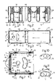
- Each element as is clearly seen in Figure 1, comprises essentially an upper plate 3 and a lower plate 4 which are substantially flat and which are adapted to take up horizontal positions when the staircase is assembled.
- the lower plate 4 and the upper plate 3 of each element are adapted to bear against the upper plate 3 and the lower plate 4 respectively of the contiguous element, as is clearly seen in Figure 1.
- Each element includes adjustment and fixing means generally indicated 5 for enabling the upper plate 3 to be displaced relative to the lower plate 4 of each element in a direction substantially perpendicular to the plates themselves; the said means also enable these plates to be fixed together in a predetermined position corresponding to a desired distance between them and hence to a desired height of the riser of the respective step tread 2.
- the adjustment and clampping means comprise at least one pair of flat walls 7 fixed to the upper plate 3 perpendicular thereto and at least one second pair of flat walls 8 fixed to the lower plate 4 perpendicular thereto; the adjustment and fixing means 5 moreover also include threaded connecting members for fixing the first pair of flat walls 7 in a predetermined position relative to the second pair 8.
- each of the support elements 1 includes a lower hollow body 12 (Figures 1, 2 and 3) and an upper hollow body 13 ( Figures 1, 4 and 5) each of which is of substantially parallelepipedal shape;
- the lower hollow body 12 ( Figures 2 and 3) is defined by two pairs of flat side walls, one pair of which is constituted by the walls 8 mentioned above and the other by walls 14 perpendicular thereto as well as by the lower plate 4.
- the upper hollow body 13 ( Figures 4 and 5) is also defined by two pairs of side walls, one pair of which is constituted by the walls 7 mentioned above and the other by walls 15 perpendicular thereto, as well as by the upper plate 3.
- the upper hollow body 13 is adapted to be connected in the manner shown in Figures 1 and 7, to the lower body 12 so that the side walls of the upper body bear against the side walls of the lower one.
- the side walls 7 and 15 ( Figures 4 and 5) of the upper hollow body have holes 16 for traversal by screws 17 ( Figure 7) adapted to be screwed into corresponding threaded holes 18 ( Figures 7 and 2) in the side walls 8 and 14 of the other hollow body 12.
- each support element 1 is formed with at least one pair of holes 22 ( Figures 4 and 5) (in the embodiment illustrated, there are three holes 22) and at least one pair of female- threads 23 (three in the case of Figures 4 and 5) is fixed to this wall, each of the female threads being coaxial with one of the said holes; conveniently these female threads are formed in a pair of platelets 24 and 25 fixed to the wall 3; conveniently the first of these has a greater width and smaller thickness than that of the underlying one and both are connected to the plate 3 by welding at 26.
- each element is formed with at least one hole 29 ( Figures 3 and 7) and a slot 30, both being through-apertures; the said hole is adapted to be traversed by the threaded shank of a first bolt 31 ( Figure 1) and the slot is adapted to be traversed by the threaded shank of a second bolt 32.
- Each of these bolts also passes through one of the holes 22 of the pair of holes formed in the upper plate 3 of the contiguous element and is screwed into the corresponding female thread 23 so as to clamp one support element to the contiguous support element.
- the slot 30 is essentially in the shape of a circular sector ( Figures 3 and 7) centred on the centre of the hole 29 formed in the lower plate 4 so that, when the first bolt 31 is screwed into the corresponding female thrad 23 ( Figure 12), the support element can be rotated relative to the contiguous one substantially about the axis of this bolt.
- Each of the lower hollow bodies 12 includes a plate 35 ( Figure 2) fixed to the upper surface of the lower plate 4; this plate has a hole 29' coaxial with the hole 29 and a slot 30' the axis of which corresponds to that of the slot 30 formed in the lower plate 4.
- the slot 30' has a similar shape to that of the slot 30 but has smaller dimensions in plan than those of the slot 30, the dimensions being such as to allow solely the shank of the screw 32 to pass through, as will clearly be seen in Figure 1.
- the support element further includes a platelet 33 ( Figures 10, 1 and 12) having a periphery corresponding to the periphery of the slot 30 and adapted to be inserted in the slot itself; when the platelet 33 is inserted in the slot 30 as is seen in Figure 1, a portion of the plate 35 overlies the platelet 33 since the slot 30' formed in the plate 33 has smaller dimensions than the slot 30 formed in the plate 4.
- a platelet 33 Figures 10, 1 and 12
- the platelet 33 has at least one hole 34 (Figure 10) for traversal by the second bolt 32 ( Figure 12).
- the platelet 33 has a pair of holes 34, as shown in Figure 11; in this case the angles between the planes (indicated P 1 and P 2 ) which contain the axes of these holes and the vertical median plane (indicated P M ) of the platelet differ; these angles may be chosen to be 20030' and 30 ° .
- first and second bolts 31 and 33 respectively may be inserted in a first pair of three holes when the support element is to form a first tread depth with the contiguous element but may, alternatively, be inserted in a second pair of the three holes mentioned above when the support element is to form a second tread depth with the contiguous element.
- the upper plate 3 of each element is formed with an aperture 37 ( Figures 1,4 and 5) for the passage of a key for locking the bolts 31 and 32;
- this aperture has a substantially triangular shape.
- a bearing plate 38 is fixed to the upper surface of the upper plate 3 by, for example, welding ( Figure 8), the bearing plate being disc-shaped and also having an aperture 39 identical to the aperture 37 and superimposed thereon when the bearing plate is fixed to the upper plate; the bearing plate 38 has an annular portion 40 slightly rebated relative to the central part of the plate, as can be seen in the section of Figure 9; finally, this plate has holes 41 for traversal by screws for fixing the tread 2 ( Figure 1) which bears on the upper surface of the plate itself.
- the lower hollow body 12 has a flange 42 ( Figure 2 and 12) of semicircular shape which projects from the front part of the plate 4 of this body.
- the threaded holes 18 provided in the walls 8 and 14 of the lower hollow body 12 are formed in wall portions which are so shaped as to form vertical projections 43 the outer surfaces of which serve as guides for the inner surfaces of the walls 7 and 15 of the upper hollow body 13.
- the front wall 7 of the upper hollow body 13 is formed with a recess 45 (Figure 6) for stiffening the wall itself; in order to stiffen the upper hollow body 12 a further inner vertical wall 44 may be provided ( Figures 2 and 3).
- the support elements which have been described and which are shown in Figure 1 are adapted to constitute intermediate elements of the staircase.
- the two end elements thereof are substantially the same as those described since the lower one differs only in that it has a base plate adapted to rest on the floor while the upper one has a shorter length (in the direction of the tread) and is provided with attachment means (not shown) for connecting it to the building block to which the staircase is normally fixed.
- a further pair of flat walls 46 is fixed to the upper element 13, each of these being parallel to the wall 7 and defining therewith a cavity 47 into which the wall 8 of the lower hollow body 12 can be inserted.
- This wall 8 has a slot 48 and a bolt 49 is arranged to pass through the hole 16 in the wall 7 and through the slot 48 in the wall 8 for screwing into a corresponding threaded hole in a nut 50 fixed to the wall 46.
- the height of the steps of the staircase is fixed; for this purpose it suffices to vary the distance between the upper plate 3 and the lower plate 4 of each element, the hollow bodies 12 and 13 being displaced relative to each other; during this displacement the projections 43 ( Figure 7) of the lower hollow body 12 form guides for the corresponding walls 7 and 15 of the upper hollow body 13.
- the two hollow bodies can then be fixed to each other by means of the screws 17.
- the height adjustment is discontinuous and the minimum variation which may be achieved is equal to the distance between the holes 18 ( Figure 2).
- the hollow bodies 12 and 13 may in this case be clamped together by the tightening of the bolts 49 which deform the walls 7 and 46 resiliently and clamp the walls 8 within the corresponding cavities 47 by friction.
- each support element 1 may be fixed to a contiguous underlying element and locked thereto by means of the screws 31 and 32 ( Figure 1).
- the depth of the staircase tread and the angle formed between each element and the underlying one must be determined.
- the larger one is obtained by the insertion of the bolts 31 and 32 in that pair of holes 22 in the upper plate 3 of the lowermost element which is located closer to the rear of the element itself, as shown in Figure 1.
- the screws 31 and 32 are be inserted in the other pair of holes.
- the bolts 31 and 32 are introduced through the aperture 37 in the overlying element and locked by means of a suitable key introduced through the aperture itself.
- each element relative to the contiguous one is adjusted by the simple rotation of the upper element relative to the lower one about the axis of the first bolt 31: as may be seen from Figure 12, this rotation is allowed even when the two bolts 31 and 32 have been inserted in their female threads 23 due to the presence of the slot 30 (in which it is supposed that the respective platelet 33 has not yet been inserted). Once this adjustment has been carried out, these screws are locked in their nuts so as to prevent any relative movement between the two support elements. The heads of these bolts bear on the plate 35.
- the platelet 33 is located in the slot 30 in the plate 4; the bolt 31 is then inserted in the holes 29', 29 and 22 and in the female thread 23.
- the upper element may then be rotated relative to the lower one about the axis of the bolt 31 to adjust the angular position of the first relative to the second and, when the angle has been adjusted, the bolt 32 is passed through the slot 30' in the plate 35, into a hole 34 in the platelet 33 and into the hole 22 in the plate 3 and, subsequently, this bolt and the bolt 31 are tightened.
- the platelet 33, as well as being locked in the slot 30 is clamped between the plate 4 and the plate 35 since a portion of this plate outside the periphery of the slot 30' is superposed on the platelet 33.
- the flange 42 covers the hole 22 in the plate 3 (of the lower element) in which no bolt has been inserted, preventing extraneous matter from entering this hole.
- each tread 2 is fixed to its support element, the tread being located on the plate 38 and screws being inserted in the holes 41 thereof and screwed into the material of the tread; since the peripheral edge 40 ( Figure 9) is prevented from contacting the tread by its slight rebate relative to the bearing surface of the plate 38, the tread (normally made of soft material such as wood) is not deformed locally.
- a staircase may be made from the modular support elements of the invention in which the height of the risers and the tread may be selected within predetermined ranges. Moreover the adjustment of the height is entirely independent of that of the tread depth and the respective operations for varying these parameters may be carried out quickly and simply without mutual influence.
- each pair of contiguous elements is connected by a pair of bolts (the screws 31 and 32) which give the structure obtained considerable flexural and torsional rigidity; moreover the relative angular positioning of two contiguous elements may be adjusted very precisely and this position is maintained even when the staircase is considerably stressed; in fact, whenever the platelet 33 is not used, relative rotation between two contiguous elements is prevented by the high frictional torque generated by the clamping force exerted by the pair of bolts 31 and 32; whenever, however, this plate is used, this prevents any relative rotation between the two contiguous elements whatever the force exerted by the screws 31 and 32.
- the staircase described is structurally very simple and may be produced very cheaply.
Landscapes
- Engineering & Computer Science (AREA)
- Architecture (AREA)
- Civil Engineering (AREA)
- Structural Engineering (AREA)
- Steps, Ramps, And Handrails (AREA)
- Ladders (AREA)
Applications Claiming Priority (2)
| Application Number | Priority Date | Filing Date | Title |
|---|---|---|---|
| ITTO930174A IT1260911B (it) | 1993-03-16 | 1993-03-16 | Elemento di sopporto modulare atto a costituire da appoggio per un gradino di una scala. |
| ITTO930174 | 1993-03-16 |
Publications (2)
| Publication Number | Publication Date |
|---|---|
| EP0616097A1 true EP0616097A1 (fr) | 1994-09-21 |
| EP0616097B1 EP0616097B1 (fr) | 1998-02-04 |
Family
ID=11411259
Family Applications (1)
| Application Number | Title | Priority Date | Filing Date |
|---|---|---|---|
| EP94103941A Expired - Lifetime EP0616097B1 (fr) | 1993-03-16 | 1994-03-14 | Elément de support modulaire adapté à former un support pour la marche d'un escalier |
Country Status (4)
| Country | Link |
|---|---|
| US (1) | US5475954A (fr) |
| EP (1) | EP0616097B1 (fr) |
| DE (1) | DE69408351D1 (fr) |
| IT (1) | IT1260911B (fr) |
Cited By (1)
| Publication number | Priority date | Publication date | Assignee | Title |
|---|---|---|---|---|
| FR2803614A1 (fr) | 2000-01-11 | 2001-07-13 | Jean Louis Fel | Escalier modulaire pour l'amenagement d'un talus forme a partir de caissons raccordes les uns aux autres |
Families Citing this family (4)
| Publication number | Priority date | Publication date | Assignee | Title |
|---|---|---|---|---|
| ATE288527T1 (de) * | 1996-07-17 | 2005-02-15 | Dieter Glockner | Treppenholm für eine mittelholmtreppe |
| US10106986B2 (en) | 2015-09-02 | 2018-10-23 | Moritz O. Bergmeyer | Curved pathway |
| US9840847B2 (en) | 2015-09-02 | 2017-12-12 | Moritz O. Bergmeyer | Curved staircase |
| RU181661U1 (ru) * | 2018-04-04 | 2018-07-26 | Михаил Сергеевич Галкин | Опорный модуль для ступеней лестницы |
Citations (6)
| Publication number | Priority date | Publication date | Assignee | Title |
|---|---|---|---|---|
| US3099336A (en) | 1960-11-14 | 1963-07-30 | Floyd L Hawkins | Prefabricated stair |
| FR1443918A (fr) | 1965-02-12 | 1966-07-01 | élément de marche d'escalier | |
| DE2256555A1 (de) * | 1972-11-17 | 1974-05-22 | Ake Bertil Carlsen | Stufenelement fuer treppe |
| DE2710641A1 (de) | 1976-03-22 | 1977-09-29 | Oswald Rada | Treppe, deren trittplatten an mindestens einem treppenbalken befestigt sind |
| EP0060014A1 (fr) * | 1981-01-21 | 1982-09-15 | GRS International Inc., | Volée d'escalier autoportante et modulaire |
| FR2590632A1 (fr) * | 1984-05-30 | 1987-05-29 | Govi Roger | Limon d'escalier modulaire |
Family Cites Families (15)
| Publication number | Priority date | Publication date | Assignee | Title |
|---|---|---|---|---|
| US1336433A (en) * | 1917-05-17 | 1920-04-13 | George W Hudson | Combined table and ironing-board |
| US3343316A (en) * | 1964-10-14 | 1967-09-26 | Frank C Mcintire | Prefabricated step for stepway construction |
| DE2249280A1 (de) * | 1972-10-07 | 1974-04-18 | Klaus Grupp | Treppe aus fertigelementen |
| DE2623523A1 (de) * | 1976-05-26 | 1977-12-15 | Zimmermann Erich | Treppentragkonstruktion |
| DE2813199C2 (de) * | 1978-03-25 | 1985-01-10 | Hans-Reiner Dipl.-Ing. 3000 Hannover Eilers | Freitragende Treppe mit einem Mittelholm, der aus einzelnen Elementen besteht |
| US4296577A (en) * | 1979-10-22 | 1981-10-27 | Schuette Heinz G | Helical staircase support |
| IT1145800B (it) * | 1981-12-31 | 1986-11-12 | Roberto Molinazzi | Supporto modulare per gradini di scale |
| DE3382330D1 (de) * | 1982-09-14 | 1991-08-08 | Yamazaki Keiichiro | Montagetreppeneinheit fuer eine treppe. |
| DE3446066A1 (de) * | 1984-12-18 | 1986-06-19 | Horst Walter 7800 Freiburg Pollehn | Verbindungsteil sowie verfahren insbesondere zum verbinden von trittstufen o.dgl. |
| US4619084A (en) * | 1985-01-28 | 1986-10-28 | Snitman Bernard H | Articulating, self-supporting staircase |
| IT1201580B (it) * | 1986-10-16 | 1989-02-02 | Indexstudio Sas Di Molinazzi & | Supporto modulare per gradini di scale |
| CA2007032C (fr) * | 1989-01-27 | 1997-09-30 | Keiichiro Yamazaki | Escalier escamotable |
| JPH03100257A (ja) * | 1989-09-13 | 1991-04-25 | Keiichiro Yamazaki | 組立式階段 |
| US5134820A (en) * | 1990-10-16 | 1992-08-04 | Liu Ing Nan | Adjustable built-up stair |
| US5088248A (en) * | 1991-03-06 | 1992-02-18 | Edwin H. Paul | Stairtread with positioning and locking mechanism |
-
1993
- 1993-03-16 IT ITTO930174A patent/IT1260911B/it active IP Right Grant
-
1994
- 1994-03-14 DE DE69408351T patent/DE69408351D1/de not_active Expired - Lifetime
- 1994-03-14 US US08/212,055 patent/US5475954A/en not_active Expired - Fee Related
- 1994-03-14 EP EP94103941A patent/EP0616097B1/fr not_active Expired - Lifetime
Patent Citations (6)
| Publication number | Priority date | Publication date | Assignee | Title |
|---|---|---|---|---|
| US3099336A (en) | 1960-11-14 | 1963-07-30 | Floyd L Hawkins | Prefabricated stair |
| FR1443918A (fr) | 1965-02-12 | 1966-07-01 | élément de marche d'escalier | |
| DE2256555A1 (de) * | 1972-11-17 | 1974-05-22 | Ake Bertil Carlsen | Stufenelement fuer treppe |
| DE2710641A1 (de) | 1976-03-22 | 1977-09-29 | Oswald Rada | Treppe, deren trittplatten an mindestens einem treppenbalken befestigt sind |
| EP0060014A1 (fr) * | 1981-01-21 | 1982-09-15 | GRS International Inc., | Volée d'escalier autoportante et modulaire |
| FR2590632A1 (fr) * | 1984-05-30 | 1987-05-29 | Govi Roger | Limon d'escalier modulaire |
Cited By (1)
| Publication number | Priority date | Publication date | Assignee | Title |
|---|---|---|---|---|
| FR2803614A1 (fr) | 2000-01-11 | 2001-07-13 | Jean Louis Fel | Escalier modulaire pour l'amenagement d'un talus forme a partir de caissons raccordes les uns aux autres |
Also Published As
| Publication number | Publication date |
|---|---|
| DE69408351D1 (de) | 1998-03-12 |
| IT1260911B (it) | 1996-04-29 |
| US5475954A (en) | 1995-12-19 |
| ITTO930174A1 (it) | 1994-09-16 |
| ITTO930174A0 (it) | 1993-03-16 |
| EP0616097B1 (fr) | 1998-02-04 |
Similar Documents
| Publication | Publication Date | Title |
|---|---|---|
| US4352485A (en) | Variable rack stair rail assembly | |
| US4625483A (en) | Connector system for furniture panels | |
| CA2269189C (fr) | Montant de soutien de lissage | |
| US7306203B2 (en) | Post assembly and spacer for use therewith | |
| US3969871A (en) | Fastening construction for playground equipment | |
| US20110167740A1 (en) | Method and Apparatus for Attaching a Rail Support Post to a Stair | |
| US5475954A (en) | Modular support element adapted to form a support for a tread of a staircase | |
| EP3481256B1 (fr) | Système d'assemblage comportant un niveleur pour element de meuble et articles d'ameublement | |
| EP0129514B1 (fr) | Système d'escalier préfabriqué avec composants modulaires | |
| US4516367A (en) | Modular support for stairway steps | |
| GB2582838A (en) | A decking assembly and decking support assembly | |
| EP0306776B1 (fr) | Unité d'escalier de montage pour un escalier | |
| JP3347089B2 (ja) | 机 | |
| US6106181A (en) | Control apparatus with control panel | |
| US5737884A (en) | Spiral stair case | |
| US4417429A (en) | Freestanding stair assembly and riser therefor | |
| US6247282B1 (en) | Deck and beam connector | |
| US5581965A (en) | Floor structure | |
| WO1990007041A1 (fr) | Attache reglable de montage d'unites de marches | |
| GB2225800A (en) | Portable barrier | |
| JPH0417722Y2 (fr) | ||
| US20060010621A1 (en) | Hybrid modular ramp | |
| US11970865B2 (en) | Modular staircase systems | |
| DE3336017A1 (de) | Stufenelement fuer den treppenbau | |
| US5054951A (en) | Arrangement for the connection of tubes |
Legal Events
| Date | Code | Title | Description |
|---|---|---|---|
| PUAI | Public reference made under article 153(3) epc to a published international application that has entered the european phase |
Free format text: ORIGINAL CODE: 0009012 |
|
| AK | Designated contracting states |
Kind code of ref document: A1 Designated state(s): BE DE ES FR GB SE |
|
| K1C1 | Correction of patent application (title page) published |
Effective date: 19940921 |
|
| 17P | Request for examination filed |
Effective date: 19950316 |
|
| 17Q | First examination report despatched |
Effective date: 19960614 |
|
| GRAG | Despatch of communication of intention to grant |
Free format text: ORIGINAL CODE: EPIDOS AGRA |
|
| GRAG | Despatch of communication of intention to grant |
Free format text: ORIGINAL CODE: EPIDOS AGRA |
|
| GRAH | Despatch of communication of intention to grant a patent |
Free format text: ORIGINAL CODE: EPIDOS IGRA |
|
| GRAH | Despatch of communication of intention to grant a patent |
Free format text: ORIGINAL CODE: EPIDOS IGRA |
|
| GRAA | (expected) grant |
Free format text: ORIGINAL CODE: 0009210 |
|
| AK | Designated contracting states |
Kind code of ref document: B1 Designated state(s): BE DE ES FR GB SE |
|
| PG25 | Lapsed in a contracting state [announced via postgrant information from national office to epo] |
Ref country code: FR Free format text: LAPSE BECAUSE OF FAILURE TO SUBMIT A TRANSLATION OF THE DESCRIPTION OR TO PAY THE FEE WITHIN THE PRESCRIBED TIME-LIMIT Effective date: 19980204 Ref country code: ES Free format text: THE PATENT HAS BEEN ANNULLED BY A DECISION OF A NATIONAL AUTHORITY Effective date: 19980204 Ref country code: BE Free format text: LAPSE BECAUSE OF FAILURE TO SUBMIT A TRANSLATION OF THE DESCRIPTION OR TO PAY THE FEE WITHIN THE PRESCRIBED TIME-LIMIT Effective date: 19980204 |
|
| REF | Corresponds to: |
Ref document number: 69408351 Country of ref document: DE Date of ref document: 19980312 |
|
| PG25 | Lapsed in a contracting state [announced via postgrant information from national office to epo] |
Ref country code: SE Free format text: LAPSE BECAUSE OF FAILURE TO SUBMIT A TRANSLATION OF THE DESCRIPTION OR TO PAY THE FEE WITHIN THE PRESCRIBED TIME-LIMIT Effective date: 19980504 Ref country code: GB Free format text: LAPSE BECAUSE OF NON-PAYMENT OF DUE FEES Effective date: 19980504 |
|
| PG25 | Lapsed in a contracting state [announced via postgrant information from national office to epo] |
Ref country code: DE Free format text: LAPSE BECAUSE OF FAILURE TO SUBMIT A TRANSLATION OF THE DESCRIPTION OR TO PAY THE FEE WITHIN THE PRESCRIBED TIME-LIMIT Effective date: 19980505 |
|
| EN | Fr: translation not filed | ||
| PLBE | No opposition filed within time limit |
Free format text: ORIGINAL CODE: 0009261 |
|
| STAA | Information on the status of an ep patent application or granted ep patent |
Free format text: STATUS: NO OPPOSITION FILED WITHIN TIME LIMIT |
|
| GBPC | Gb: european patent ceased through non-payment of renewal fee |
Effective date: 19980504 |
|
| 26N | No opposition filed |