EP0616155A1 - Quetschventil - Google Patents
Quetschventil Download PDFInfo
- Publication number
- EP0616155A1 EP0616155A1 EP94850035A EP94850035A EP0616155A1 EP 0616155 A1 EP0616155 A1 EP 0616155A1 EP 94850035 A EP94850035 A EP 94850035A EP 94850035 A EP94850035 A EP 94850035A EP 0616155 A1 EP0616155 A1 EP 0616155A1
- Authority
- EP
- European Patent Office
- Prior art keywords
- cam
- permanent magnet
- tube
- occluding
- stator
- Prior art date
- Legal status (The legal status is an assumption and is not a legal conclusion. Google has not performed a legal analysis and makes no representation as to the accuracy of the status listed.)
- Granted
Links
- 230000007246 mechanism Effects 0.000 claims abstract description 34
- 238000001631 haemodialysis Methods 0.000 claims description 31
- 230000000322 hemodialysis Effects 0.000 claims description 31
- 239000008280 blood Substances 0.000 claims description 19
- 210000004369 blood Anatomy 0.000 claims description 19
- 239000012530 fluid Substances 0.000 claims description 10
- 230000000717 retained effect Effects 0.000 claims description 6
- 230000002572 peristaltic effect Effects 0.000 claims description 5
- 230000017531 blood circulation Effects 0.000 claims description 4
- 230000002093 peripheral effect Effects 0.000 claims description 4
- 238000005086 pumping Methods 0.000 claims description 4
- 230000001351 cycling effect Effects 0.000 claims description 3
- 229910052761 rare earth metal Inorganic materials 0.000 claims description 3
- 150000002910 rare earth metals Chemical group 0.000 claims description 3
- KPLQYGBQNPPQGA-UHFFFAOYSA-N cobalt samarium Chemical compound [Co].[Sm] KPLQYGBQNPPQGA-UHFFFAOYSA-N 0.000 claims description 2
- ZWKKPKNPCSTXGA-UHFFFAOYSA-N iron neodymium Chemical compound [Fe].[Fe].[Nd] ZWKKPKNPCSTXGA-UHFFFAOYSA-N 0.000 claims description 2
- 229910000938 samarium–cobalt magnet Inorganic materials 0.000 claims description 2
- 238000000502 dialysis Methods 0.000 description 7
- 230000009471 action Effects 0.000 description 5
- 230000005672 electromagnetic field Effects 0.000 description 4
- 230000001965 increasing effect Effects 0.000 description 4
- 238000004804 winding Methods 0.000 description 4
- 230000000295 complement effect Effects 0.000 description 3
- 230000004044 response Effects 0.000 description 3
- XEEYBQQBJWHFJM-UHFFFAOYSA-N Iron Chemical compound [Fe] XEEYBQQBJWHFJM-UHFFFAOYSA-N 0.000 description 2
- 229910000831 Steel Inorganic materials 0.000 description 2
- 230000009977 dual effect Effects 0.000 description 2
- 238000009429 electrical wiring Methods 0.000 description 2
- 230000020169 heat generation Effects 0.000 description 2
- 230000007794 irritation Effects 0.000 description 2
- 210000003734 kidney Anatomy 0.000 description 2
- 229910052751 metal Inorganic materials 0.000 description 2
- 239000002184 metal Substances 0.000 description 2
- 239000010959 steel Substances 0.000 description 2
- 210000003462 vein Anatomy 0.000 description 2
- 239000002699 waste material Substances 0.000 description 2
- 229910000859 α-Fe Inorganic materials 0.000 description 2
- 230000004888 barrier function Effects 0.000 description 1
- 230000000903 blocking effect Effects 0.000 description 1
- 230000008859 change Effects 0.000 description 1
- 238000010276 construction Methods 0.000 description 1
- 238000002788 crimping Methods 0.000 description 1
- 230000001934 delay Effects 0.000 description 1
- 230000001939 inductive effect Effects 0.000 description 1
- 229910052742 iron Inorganic materials 0.000 description 1
- 239000000463 material Substances 0.000 description 1
- 238000000034 method Methods 0.000 description 1
- 230000004048 modification Effects 0.000 description 1
- 238000012986 modification Methods 0.000 description 1
- 229910001172 neodymium magnet Inorganic materials 0.000 description 1
- 238000000819 phase cycle Methods 0.000 description 1
- 230000001846 repelling effect Effects 0.000 description 1
- 239000000126 substance Substances 0.000 description 1
Images


Classifications
-
- F—MECHANICAL ENGINEERING; LIGHTING; HEATING; WEAPONS; BLASTING
- F16—ENGINEERING ELEMENTS AND UNITS; GENERAL MEASURES FOR PRODUCING AND MAINTAINING EFFECTIVE FUNCTIONING OF MACHINES OR INSTALLATIONS; THERMAL INSULATION IN GENERAL
- F16K—VALVES; TAPS; COCKS; ACTUATING-FLOATS; DEVICES FOR VENTING OR AERATING
- F16K7/00—Diaphragm valves or cut-off apparatus, e.g. with a member deformed, but not moved bodily, to close the passage ; Pinch valves
- F16K7/02—Diaphragm valves or cut-off apparatus, e.g. with a member deformed, but not moved bodily, to close the passage ; Pinch valves with tubular diaphragm
- F16K7/04—Diaphragm valves or cut-off apparatus, e.g. with a member deformed, but not moved bodily, to close the passage ; Pinch valves with tubular diaphragm constrictable by external radial force
- F16K7/045—Diaphragm valves or cut-off apparatus, e.g. with a member deformed, but not moved bodily, to close the passage ; Pinch valves with tubular diaphragm constrictable by external radial force by electric or magnetic means
Definitions
- This invention relates generally to an apparatus for controlling the flow of a fluid in a flexible tubing. It is particularly well suited for controlling blood flow in single needle hemodialysis machines and related medical and biotechnological applications.
- the control of fluid flow through flexible tubing is required in many technical fields of endeavor, including routine laboratory practices, and the chemical, biotechnological and medical fields.
- the present invention relates to an apparatus for clamping flexible tubes in a controlled manner so as to occlude the tube and thereby prevent the flow of fluid through the tube.
- the disclosed apparatus was developed in response to the need for an improved clamping apparatus for use in single needle hemodialysis, but will find widespread utility in many other applications.
- Hemodialysis machines serve as artificial kidneys for extracting waste material from the blood of a patient whose kidneys do not function properly. Generally, this waste is removed from the patient's blood by dialysis through semipermeable barriers into a dialysate. This dialysis is performed in a hemodialysis machine. It is therefore required that blood be removed from the patient, conveyed to the hemodialysis machine for treatment and then returned to the patient. This is achieved by means of flexible tubes and a pump mechanism, such as a peristaltic pump.
- hemodialysis In one type of hemodialysis, termed single needle hemodialysis, a single venipuncture needle is inserted into a vein in the patient's arm. This needle is used both to remove untreated blood from the patient and deliver it to the hemodialysis machine and to return treated blood to the patient from the hemodialysis machine. This blood removal and return is performed through two separate flexible tubes, both of which are operably attached to the single needle.
- the dialysis machine operates on a dual phase cycle: in one phase, termed the arterial phase, blood is withdrawn from the patient through the needle and passed through one of the tubes, termed the arterial line, into the dialysis machine for treatment. During this arterial phase, the other tube, termed the venous line, is occluded. In the other phase, termed the venous phase, treated blood is pumped from the dialysis machine through the venous line, and returned to the patient through the needle, while the arterial line is occluded.
- the operation of a typical single needle hemodialysis apparatus is disclosed in United States Patent No. 4,643,714.
- the pumping action required to convey the blood to and from the patient is typically performed by a peristaltic pump, such as is disclosed in United States Patent No. 4,190,536.
- the arterial and venous lines are typically made of flexible tubing. Clamps are used to occlude the arterial or venous lines as appropriate to the phase of the machine. The occlusion of the tubes may be achieved by means of a single clamp (as disclosed in U.S. Patent No. 4,061,142) or by two separate clamps -an arterial line clamp and a venous line clamp.
- the clamp on the arterial line is normally open; that is, when power is withheld from the clamp, the tubing is open.
- the venous line clamp must be occluded when the clamp is not receiving power (hence the venous line clamp may also be referred to as the "safety clamp").
- a micro-proces- sorwithin the hemodialysis machine regulates the cycling of blood flow and controls the opening and closing of the arterial and venous line clamps.
- Typical clamping devices used to occlude the flexible tubing make use of a solenoid and lifting magnets which are connected to a clamping mechanism. These clamps typically require large amounts of power, leading to the generation of significant amounts of heat during operation.
- These solenoid clamps have been known to fail because of elevated temperatures during operating conditions.
- conventional solenoid clamps also generate considerable noise during operation, providing, in addition to the dialysis itself, an additional irritation to the patient.
- a further disadvantage of conventional solenoid-based clamps is that these clamps respond relatively slowly to signals received from the hemodialysis machine microprocessor. Delays in opening or closing the clamps can result in admixing of treated and untreated blood.
- the present invention provides a line clamp apparatus useful for occluding a flexible tube.
- the line clamp employs a permanent magnet rotary actuator operably connected to a rotatable cam that provides a clamping action to occlude the flexible tube.
- the apparatus is useful as an arterial line clamp for a single needle hemodialysis machine.
- the tubing is normally open.
- the rotatable cam is caused to rotate and occlude the tubing. This rotary action opposes and overcomes a biasing force generated by a spring mechanism; when power is removed from the rotary actuator, the spring mechanism rotatably returns the cam to an "open" position such that fluid is allowed to flow through the tube.
- the apparatus is useful as a venous line clamp (also termed a "safety clamp") for a single needle hemodialysis machine.
- the tubing is normally occluded. This is achieved by means of a spring mechanism operably connected to the rotatable cam. This spring mechanism holds the rotatable cam in a “closed” position such that the tubing is normally occluded.
- the rotatable cam is caused to rotate against the force of the spring mechanism to open the flexible tube and permit fluid flow therethrough.
- the permanent magnet rotary actuator comprises a permanent magnet rotatably supported within a housing and a stator fixed in the housing so as to be diametrically separated from the outer peripheral surface of the permanent magnet, the stator having coils wound on projections extending toward the permanent magnet.
- a drive shaft is coupled to the permanent magnet and operably attached at one end to the rotatable cam.
- the present invention therefore makes use of a permanent magnet direct drive device rather than an inductive solenoid device typical of conventional line clamps.
- the stator in the permanent magnet rotary actuator is provided with six circumferentially spaced electromagnets which correspond to six pole portions of alternating polarity on the permanent magnet.
- the permanent magnet and the attached drive shaft rotate through a theoretical maximum of 60°. This rotation is directly translated into rotation of the rotatable cam.
- a rotation-limiting means is provided to limit the rotation of the permanent magnet and drive shaft.
- the rotation limiting means comprises at least one pin connected to the permanent magnet and at least one raceway defined by a plate into which the pin projects.
- the pins are protected by a plastic sleeve which serves to deaden the noise produced.
- the rotation limiting means comprises a rotation-limiting cam operably connected to the permanent magnet and a fixed stop that restricts the movement of the rotation-limiting cam.
- a resistance means for opposing the movement of the tube occluding cam is provided.
- this resistance means maintains the tube occluding cam in an "open” position such that the tubing is non-occluded when power is withheld from the clamp.
- the resistance means maintains the tube occluding cam in a "closed" position (tube occluded) when power is withheld.
- the resistance means comprises at least one spring having two ends and being operably connected at one end to a fixed plate and operably connected at the other end to the permanent magnet.
- the direct drive design of the present invention efficiently generates sufficient torque to counter-act the spring-biasing mechanism. This allows the actuator to function on a lower power supply than conventional solenoid line clamps, alleviating the significant heat generation problems associated with these prior clamps.
- FIG. 1 illustrates the use of the line clamps of the present invention in the context of single needle hemodialysis. This use is provided by way of illustration only, and is not intended to designate a limitation on the use of the present invention.
- the line clamps of the present invention may be used in many contexts in which the control of fluid flow through a flexible tube is required, and is particularly well suited for medical and biotechnological applications.
- FIG. 1 there is shown a schematic illustration of a single needle hemodialysis apparatus 20 for removing untreated blood from a patient through a single needle 22 inserted into a vein (not shown) in a patient's arm 24.
- An arterial line 26 is connected to the needle 22 for removal of blood from the patient.
- a venous line 28 also is connected to the needle 22 for returning treated blood to the patient.
- An arterial line clamp 30 and venous line clamp 32 are located on the arterial and venous lines, 26 and 28, respectively, for alternately blocking flow through these lines.
- Blood removed from the patient is pumped through arterial line 26 to the hemodialysis machine 34 where it is treated (not shown) and returned to the patient through venous line 28.
- Pumping is achieved by a pumping means, such as a peristaltic pump (not shown), located within the hemodialysis machine 34.
- the hemodialysis machine typically is contained within a frame or housing 36.
- the arterial and venous line clamps, 30 and 32 are mounted onto an outer surface of frame 36 in a conventional manner.
- Each of the line clamps has a tube receiving member 38 which provides a channel or seat to retain a portion of the line clamp, again in a conventional manner.
- Tube receiving member 38 serves to hold the flexible tube in place next to a rotatable cam (or"tube-occluding cam") 40 which, when rotated in one direction, occludes the flexible tube by pinching it against a side wall of the channel.
- a rotatable cam 40 of arterial line clamp 30 is shown in the open position such that blood may flow through arterial line 26 to the hemodialysis machine.
- the rotatable cam 40 of venous line clamp 32 is shown in the closed position, thereby occluding venous line 28 and preventing the flow of processed blood to the patient.
- Arterial line clamp 30, venous line clamp 32 and the peristaltic pump are electrically connected to receive signals from a microprocessor based electronic controller (not shown) within the hemodialysis machine 34 in a manner known in the hemodialysis art.
- Arterial line clamp 30 receives control signals from the controller through an electrical line 42
- venous line clamp 32 receives control signals from the controller through electrical line 44.
- the controller receives feedback electrical signals from Hall sensors (not shown) in arterial line clamp 30 and venous line clamp 32 through electrical lines 46 and 48 respectively. Signals received by the controller through lines 46 and 48 provide information on the respective positions of both rotatable cams 40.
- electrical line 46 provides a signal to the controller indicating that arterial line clamp 30 is in the "open” or non-occluded position
- electrical line 48 provides a signal to the controller indicating that venous clamp 32 is in the "closed” or occluded position.
- FIG. 2 shows an exploded view of arterial line clamp 30 according to one embodiment of the present invention.
- Clamp 30 includes a rotary actuator for automatically generating a clamping torque in response to signals from a microprocessor or other control means.
- the rotary actuator includes a stator 52 that defines a hollow cylindrical bore 54 into which a permanent magnet-drive shaft assembly 56 is located.
- stator 52 is provided with six inwardly protruding projections 58a-58f, circumferentially spaced from one another around bore 54.
- projections 58a-58f are each wrapped with respective coils 60a-60f in a conventional manner to form six electromagnets.
- coils 60a-60f are formed by winding a single length of wire around each projection. The winding direction alternates around successive projections such that coils 60a, 60c and 60e are (for example) wound clockwise and coils 60b, 60d and 60f are wound counter-clockwise.
- each coil will comprise approximately 350 windings of the wire.
- a suitable wire would be 28 gauge single build insulated thermal class 155 (with a maximum diameter of 0.38 mm, 58.6 ohm resistance per 1000 feet at 20°C).
- the coils 60a-60f form a coil means in which diametrically opposed coils, when energized, have opposite polarities and adjacent coils have opposite polarities, such that the projections produce circumferentially alternating north, south magnetic poles.
- the stator 52 and its component projections 58a-f are formed of non-permanent, but magnetizable material such as soft iron.
- the permanent magnet-drive shaft assembly 56 comprises a cylindrical permanent magnet rotor62, cylindrical backing sleeve 64 and drive shaft insert 66.
- the permanent magnet rotor defines a cylindrical bore into which the cylindrical backing sleeve 64 is snugly press fit or otherwise secured, the outer diameter of the backing sleeve being slightly less than the inner diameter of the magnet rotor.
- the cylindrical backing sleeve 64 also defines an internal cylindrical bore into which the drive shaft insert 66 is inserted, again with the outer diameter of the shaft insert being slightly less than the inner diameter of the backing sleeve.
- the drive shaft insert has a radially expanded collarwhich rests against an end wall of the backing sleeve when the drive shaft insert is inserted therein.
- the drive shaft insert is fixedly fastened to the backing sleeve by a pair of screws passing through openings 68 in the collar of the drive shaft insert and then threading into corresponding aligned threaded openings 69 in the backing sleeve.
- the backing sleeve and drive shaft insert assembly is then inserted inside rotor 62 to form part of assembly 56.
- Assembly 56 also includes a drive shaft 138 which is inserted coaxially into the internal bore of shaft insert 66.
- the drive shaft has a central portion of square cross section which is seated in a complementary shaped square opening provided in a raised end portion 71 (FIG. 2) of shaft insert 66, thereby preventing the drive shaft from rotating relative to shaft insert 66.
- the permanent magnet drive shaft assembly including magnet 62, backing sleeve 64, shaft insert 66, drive shaft 138 and cam 40 coupled to the operative end of shaft 138, rotates as a unit.
- This drive shaft assembly is rotatably supported by a bearing 72 seated within a bearing sleeve 74.
- Sleeve 74 in turn is secured to central portion of a bearing plate 76.
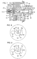
- the foregoing drive shaft assembly is rotatably supported at a protruding end portion of drive shaft 138 which is jour- nailed in bearing 72, as FIG. 4 illustrates.
- the drive shaft and other components coupled thereto are retained axially in place by a retainer clip 70 (FIG. 2) fastened on the protruding end portion of the drive shaft just outboard of shaft insert 66.
- Bearing plate 76 is attached to stator 52 by standoff rivets 78, 80 and 82 and bearing plate-stator screws 84, 86 and 88 which thread into threaded openings in the heads of the standoff rivets.
- the rivets are fastened to the stator within appropriately positioned openings (not shown) in a peripheral end wall portion of the stator.
- Stop pins 90 and 92 are threadedly fastened into an end wall portion of backing sleeve 64 for rotation therewith. Stop pins 90 and 92 project from the backing sleeve through respective raceways 94 and 96 cut in bearing plate 76.
- the stop pins are each provided with cushioning means which, in this preferred embodiment, includes respective plastic sleeves 98 and 100.
- raceways 94,96 define stop limits for the movement of the stop pins.
- the raceways which have an arcuate configuration due to the rotational movement of the rotary actuator, preferably permit the stop pins to travel along a circular path of about 45°.
- Sleeves 100 muffle the noise created as the stop pins periodically contact the stop limits by preventing the metal to metal contact which would otherwise occur.
- a cylindrical spring 101 is attached at one end to each stop pin 90, 92 and at its other end to a respective anchor pin 102, 104.
- the springs act as a counterbalanced biasing means urging the stop pins to move to the end of their respective raceways closest to the anchor, thereby forcing the rotary actuator coupled thereto to its "open" non-occluded position unless counteracted by a greater rotational force.
- Each mounting tube is a hollow plastic cylinder which passes between a pair of coils carried by stator 52 and terminates at a base plate 120.
- the function of the mounting tubes is to allow access to fastening means for fastening base plate 120 to a mounting plate 130.
- base plate 120 is mounted proximate to one side of stator 52 by means of standoff rivets 132, 134 and 136, and base plate stator screws 122,124 and 126 which thread into respective heads of rivets 132, 134, 136.
- Mounting plate 130 in turn is attached to the base plate 120 by means of screws (not shown) passing through the mounting tubes 156 and threading into the inboard side of the mounting plate. Tubes 156 provide access openings for a screwdriver to engage the screws without contacting and possibly damaging coils 60.
- the tube receiving member 38 defines two parallel cylindrical bores, one of which is coincident with the longitudinal center axis of drive shaft 138. This coincident bore seats the drive shaft, while the other offset bore seats a cover shaft 140 to which a tube cover 148 is pivotally mounted.
- Tube receiving member 38 also defines a complementary shaped groove 142 (FIG. 2) into which rotatable cam 40 nests to provide clearance for the adjacent flexible tube. When the cam is located flush in the groove, the cam and tube receiving member 38 to- getherform a channel with substantially parallel sides to laterally retain the flexible tube.
- cover 148 is pivoted on its supporting cover shaft to a closed position in which the cover overlies the flexible tube to prevent same from being displaced out of the channel.
- Acover shaft retainer clip 150 (FIG. 2)
- cover shaft retainer washer 152 (FIG. 2)
- cover torsion spring 154 (FIG. 2) are seated on one end of the cover shaft between base plate 120 and stator 52 so as to axially retain the cover shaft in place and provide a biasing torque urging the cover to its closed "tube retained" position.
- a semicircular printed circuit board 158 is mounted in a conventional manner to bearing plate 76 on its outboard side.
- Circuit board 158 has a semicircular notch 160 to provide clearance for some of the components on the outboard side of bearing plate 76.
- the circuit board carries conventional electronic circuitry known in the art for directing and controlling current flow to stator coils 58a-f of stator 52. Electrical wires 164 joined to the control circuitry on the circuit board 158 pass through appropriate openings in the bearing plate to operably connect to coils 58a-f.
- the control circuitry on circuit board 158 also receives control signals from the microprocessor (not shown) or other suitable controller through electrical lines such as line 42 (FIG. 1).
- Hall sensor 166 Also mounted onto the circuit board is a conventional Hall sensor 166.
- the Hall sensor 166 projects through a slot in the bearing plate in a direction parallel to the center axis of drive shaft 138.
- Hall sensor 166 is mounted adjacent to the permanent magnet 62 such that it detects the magnetic polarity of the adjacent pole of the permanent magnet.
- the Hall sensor 166 is electrically connected to the hemodialysis machine microprocessor (not shown) by electrical wiring, such as line 46 in FIG. 1.
- FIGS. 3 and 4 schematically show the Hall sensor positioned generally between one of the stator coils and an adjacent pole portion of magnet 62. It will be appreciated that the Hall sensor is located in the magnetic field of the pole portion so as to detect rotation of the magnet when the adjacent pole orientation changes from north to south (or vice versa). This change in orientation is signalled electrically to the microprocessor which is programmed to associate the particular pole orientation of the magnet with either an "open” or "occluded” status of the clamping cam.
- FIGS. 5 and 5A there are shown horizontal sectional views taken along line 5-5 of FIG. 3, as viewed looking toward bearing plate 76.
- FIGS. 5 and 5A have illustrative arrows indicating forces applied to the permanent magnet drive shaft assembly.
- the arterial line clamp is in a normally "open” or non-occluded position, as illustrated by FIG. 5.
- the arrow of FIG. 5 represents the force applied by springs 101 to the drive shaft assembly.
- FIG. 5B shows an end view of bearing plate 76 indicating, by means of single-headed arrows, the direction of the biasing action of the springs 101 on the drive shaft 138.
- the springs When power is not supplied to the stator coils, the springs thus urge the drive shaft assembly to the angular orientation shown in FIG. 5, as determined by the stop limits of raceways 94, 96.
- This angular orientation of the drive shaft assembly positions cam 40 in the open position, as shown in FIGS. 1 and 6.
- stator coils 58a-58f When power is supplied to stator coils 58a-58f, in response to signals received from the hemodialysis machine microprocessor through the circuit board 158 and suitable electrical wiring, the electromagnetic fields are activated.
- the coils are wound so that, when energized, each coil creates an electromagnetic field of the same polarity as the permanent magnet pole portion directly across from the coil thereby applying a repelling magnet force to the permanent magnet.
- These electromagnetic fields cause the permanent magnet to rotate in a counterclockwise direction, as shown by the arrow in FIG. 5A, to a more dynamically stable position in which the permanent magnet pole portions have aligned themselves with a coil of opposite polarity.
- This rotational movement produces rotation of the drive shaft 138 and thereby, rotation of the rotatable cam 40 to its occluded position.
- the torque generated by rotation of the permanent magnet is sufficient to overcome the biasing action of the springs 101 and cause the pins 90 and 92 to move to the limits of the raceways 94 and 96, respectively, such that springs 101 are maximally extended (shown in FIG. 5B).
- the rotatable cam 40 will turn through a maximum angle of 45 degrees, as illustrated in FIG. 6, and will thereby occlude the flexible tube mounted in the tube retaining member 38.
- the maximum rotation angle of 450 is defined by the travel of pins 90 and 92 in raceways 94 and 96, respectively (FIG. 5B).
- the permanent magnet comprises a ferrite magnet, although other types of magnets may also be used.
- the arterial line clamp produces at least 8 inch pounds of torque, and preferably more than 10 inch pounds of torque.
- the rotary actuator of the present invention preferably is supplied with a 24 volt direct current power supply and draws 0.5 amps of current, therefore consuming 12 watts of power.
- the above description sets forth a preferred embodiment as an arterial line clamp in which the spring biasing mechanism causes the clamp to be in the "open” or non-occluded position when power is withheld from the electromagnet coils. It will be appreciated that essentially the same design can be utilized to produce a venous or "safety” clamp simply by arranging the drive shaft-spring biasing mechanism such that the spring biasing mechanism causes the clamp to be in a "closed” position when power is withheld from the electromagnet coils. Because of safety considerations in the single needle hemodialysis context, the biasing spring mechanism in a venous clamp context preferably is designed to supply a greater biasing force to the drive shaft assembly than springs used in an arterial clamp design.
- parameters such as type and strength of magnet, amount of power supplied to the stator coils and cam length relative to its axis of rotation, will be selected in a known manner to produce at least 10 inch pounds of torque on the cam and, preferably at least 14 inch pounds of torque.
- increased torque may be produced by using a thicker gauge of windings on the stator coils which thereby draw a greater current and produce a correspondingly stronger electromagnetic field.
- a safety clamp according to this embodiment may be supplied with a 24 volt direct current power supply and draw 1.0 amp of current, therefore consuming 24 watts of power.
- the increased torque may be obtained by utilizing a rare earth permanent magnet in place of the ferrite permanent magnet.
- Suitable rare earth permanent magnets include samarium cobalt and iron neodymium magnets.
- the clamps of the present invention operate on relatively low voltage direct current, heat generation problems associated with conventional clamps are avoided. Furthermore, the location and design of the stop mechanism (the steel stop pins mounted with noise-reducing sleeves) produce significantly less noise than conventional clamps. Finally, the clamps of the present invention are more compact, reliable and operate more efficiently than conventional solenoid design clamps.
- the preferred embodiment described above is illustrative only of the principle of the rotary actuator clamp design, and that variations in this design which rely on the underlying concept set forth herein are possible.
- the number of electromagnets in the stator and the corresponding number of pole-pairs of the permanent magnet may be increased or reduced.
- the rotation of the drive shaft is correspondingly reduced.
- FIG. 7 shows a vertical sectional view of a venous line clamp in accordance with one particular alternate embodiment of the present invention.
- the construction of this embodiment is the same as the embodiments illustrated in FIGS. 2-6, except as otherwise shown in FIGS. 7-10 and discussed below.
- FIG. 7 shows an alternative mechanism for mounting drive shaft 138 onto the drive shaft insert 66.
- a nut 180 is threaded onto externally threaded section 182 of drive shaft 138. The nut 180 thereby retains the drive shaft 138, and other components coupled thereto, axially in place in the drive shaft insert 66.
- the pin and raceway stop mechanism used to limit the maximum rotation of the drive shaft 138 is replaced by a fixed stop 168 mounted to or integrally formed on the in-board side of fixed base plate 120.
- Stop 168 carries a single tooth projection which cooperates with a cam collar (or “rotation-limiting cam") 170 mounted on drive shaft 138.
- Collar 170 has a complementary shaped square opening to receive a square portion of shaft 138 so that the collar and shaft rotate together.
- Cam collar 170 is generally circular in section, except for two arcuate notches, a first notch 169 and second notch 171, formed in the periphery of the cam collar (see FIGS. 8 and 9).
- notch 169 and the tooth of stop 168 are sized, configured and arranged to permit shaft 138 and the occluding cam 40 coupled thereto to rotate about 45° between the open and occluded positions.
- An angular rotation of the cam shaft of about 45° is selected as a preferred embodiment of the present invention, both for the cam collar herein described and the pins and raceways design described above as the preferred embodiment.
- This parameter is a function of several obvious variables, including the effective "lever" length of cam 40, configuration of cam 40 and its relative position to the flexible tube, and hence can vary depending upon the design of the line clamp. These parameters are selected such that cam 40 does not pinch or crimp the flexible tube when disposed in the open position, but does effectively and consistently occlude the flexible tube to stop all flow therethrough when disposed in the occluded position without permanently crimping or otherwise damaging the flexible tube.
- FIG. 7 also shows an alternative biasing means or spring tension mechanism 172 in place of the dual spring mechanism shown in FIGS. 2 and 5B.
- Spring tension mechanism 172 includes a helical tension spring 173 which is mounted outboard of bearing plate 76. One end of the helical tension spring is fixedly attached to a shaft extension 175 fastened to drive shaft 138 by means of a screw 174. The other end of the helical spring is fixedly fastened to bearing plate 76.
- the spring tension mechanism 172 is coupled to drive shaft 138 in a manner such that the drive shaft and its rotatable cam 40 is biased to the tube occluding position.
- the helical spring tension mechanism 172 When the stator coils are energized, the resulting electromagnetic force applied to the permanent magnet counteracts the force of the spring tension mechanism to rotate the drive shaft to the open position, as previously explained.
- the helical spring tension mechanism 172 would be coupled to drive shaft 138 in a manner such that the drive shaft and its rotatable cam 40 would be biased to the tube open position, and rotation of the permanent magnet would cause rotation of the drive shaft and thereby the rotatable cam 40 to the tube occluding position.
- FIGS. 7-10 show a manual cam release means by which cam 40 can be manually rotated into the "open" position to release the flexible tube.
- pivotable cover 148 has an integrally connected cover shaft 140 from which protrudes, at a distal end thereof, an integrally formed cam tooth 176. It will be appreciated that cover 148, shaft 140 and tooth 176 all rotate as a unit. The cam tooth projects into and cooperates with the second notch 171 of cam collar 170.
- cover 148 is closed to retain the flexible tube in its occluded position (with power off) in the channel and, therefore, is rotated, causing cam tooth 176 is inoperative.
- cover 148 is rotated, causing cam tooth 176 to rotate clockwise to the position shown in FIG. 9.
- the cam tooth engages cam collar 170, causing drive shaft 138 and occlusion cam 40 coupled thereto to rotate against the bias of the helical spring 173.
- Cam 40 is thus manually rotated to the "open" position to permit the flexible tube to be removed.
Landscapes
- Engineering & Computer Science (AREA)
- General Engineering & Computer Science (AREA)
- Mechanical Engineering (AREA)
- External Artificial Organs (AREA)
- Valve-Gear Or Valve Arrangements (AREA)
- Fluid-Driven Valves (AREA)
- Details Of Reciprocating Pumps (AREA)
- Infusion, Injection, And Reservoir Apparatuses (AREA)
- Mechanically-Actuated Valves (AREA)
- Reciprocating Pumps (AREA)
Applications Claiming Priority (2)
| Application Number | Priority Date | Filing Date | Title |
|---|---|---|---|
| US33621 | 1993-03-16 | ||
| US08/033,621 US5413566A (en) | 1993-03-16 | 1993-03-16 | Line clamp |
Publications (2)
| Publication Number | Publication Date |
|---|---|
| EP0616155A1 true EP0616155A1 (de) | 1994-09-21 |
| EP0616155B1 EP0616155B1 (de) | 1998-01-28 |
Family
ID=21871457
Family Applications (1)
| Application Number | Title | Priority Date | Filing Date |
|---|---|---|---|
| EP94850035A Expired - Lifetime EP0616155B1 (de) | 1993-03-16 | 1994-03-10 | Quetschventil |
Country Status (5)
| Country | Link |
|---|---|
| US (1) | US5413566A (de) |
| EP (1) | EP0616155B1 (de) |
| JP (1) | JPH06341374A (de) |
| AT (1) | ATE162880T1 (de) |
| DE (1) | DE69408182T2 (de) |
Families Citing this family (41)
| Publication number | Priority date | Publication date | Assignee | Title |
|---|---|---|---|---|
| JP3415275B2 (ja) * | 1994-07-08 | 2003-06-09 | カヤバ工業株式会社 | 電磁アクチュエータ |
| US5684350A (en) * | 1994-09-08 | 1997-11-04 | Kayaba Kogyo Kabushiki Kaisha | Electromagnetic rotary actuator and housing for electronic devices |
| SE9603313D0 (sv) * | 1996-09-12 | 1996-09-12 | Siemens Elema Ab | Flödesregulator |
| AUPR117100A0 (en) * | 2000-11-02 | 2000-11-23 | Noble House Group Pty Ltd | Means for stripping blood lines |
| US6722865B2 (en) | 2001-09-07 | 2004-04-20 | Terumorcardiovascular Systems Corporation | Universal tube clamp assembly |
| US7367358B2 (en) * | 2005-02-02 | 2008-05-06 | Universal Infusion Technology, Llc | Medical fluid delivery system and method relating to the same |
| JP2007226175A (ja) * | 2006-01-26 | 2007-09-06 | Epson Imaging Devices Corp | 液晶装置及び電子機器 |
| EP2724736B1 (de) | 2006-04-14 | 2022-06-08 | DEKA Products Limited Partnership | Kassette mit eingehauster pumpe |
| US10537671B2 (en) | 2006-04-14 | 2020-01-21 | Deka Products Limited Partnership | Automated control mechanisms in a hemodialysis apparatus |
| US8425471B2 (en) | 2007-02-27 | 2013-04-23 | Deka Products Limited Partnership | Reagent supply for a hemodialysis system |
| US8357298B2 (en) | 2007-02-27 | 2013-01-22 | Deka Products Limited Partnership | Hemodialysis systems and methods |
| US20090107335A1 (en) | 2007-02-27 | 2009-04-30 | Deka Products Limited Partnership | Air trap for a medical infusion device |
| US8409441B2 (en) | 2007-02-27 | 2013-04-02 | Deka Products Limited Partnership | Blood treatment systems and methods |
| US8888470B2 (en) | 2007-02-27 | 2014-11-18 | Deka Products Limited Partnership | Pumping cassette |
| US9028691B2 (en) | 2007-02-27 | 2015-05-12 | Deka Products Limited Partnership | Blood circuit assembly for a hemodialysis system |
| US8042563B2 (en) | 2007-02-27 | 2011-10-25 | Deka Products Limited Partnership | Cassette system integrated apparatus |
| US8562834B2 (en) | 2007-02-27 | 2013-10-22 | Deka Products Limited Partnership | Modular assembly for a portable hemodialysis system |
| US8393690B2 (en) | 2007-02-27 | 2013-03-12 | Deka Products Limited Partnership | Enclosure for a portable hemodialysis system |
| US8491184B2 (en) | 2007-02-27 | 2013-07-23 | Deka Products Limited Partnership | Sensor apparatus systems, devices and methods |
| KR101861192B1 (ko) | 2007-02-27 | 2018-05-28 | 데카 프로덕츠 리미티드 파트너쉽 | 혈액투석 장치 및 방법 |
| US8771508B2 (en) | 2008-08-27 | 2014-07-08 | Deka Products Limited Partnership | Dialyzer cartridge mounting arrangement for a hemodialysis system |
| EP2246080B1 (de) * | 2007-10-12 | 2016-02-10 | DEKA Products Limited Partnership | Extrakorporaler blutkreislauf |
| US8863772B2 (en) * | 2008-08-27 | 2014-10-21 | Deka Products Limited Partnership | Occluder for a medical infusion system |
| EP2222957B1 (de) | 2007-12-10 | 2017-01-25 | Bayer Healthcare LLC | System und verfahren für kontinuierliche flüssigkeitsausgabe |
| MX340210B (es) | 2008-01-23 | 2016-06-29 | Deka Products Ltd Partnership * | Componentes desechables para sistemas y métodos de autoconexión de una linea de fluido. |
| WO2011053810A2 (en) | 2009-10-30 | 2011-05-05 | Deka Products Limited Partnership | Apparatus and method for detecting disconnection of an intravascular access device |
| WO2011100703A1 (en) * | 2010-02-12 | 2011-08-18 | Aspen Motion Technologies Inc. D/B/A | Vacuum valve apparatus and method |
| US10035979B2 (en) | 2015-07-23 | 2018-07-31 | Picobrew, Inc. | Beer making machine with direct steam injection |
| US11678760B2 (en) | 2011-03-03 | 2023-06-20 | PB Funding Group, LLC | Multifunctional brewing system for coffee, beer, and other beverages |
| US11753610B2 (en) | 2011-03-03 | 2023-09-12 | PB Funding Group, LLC | Self healing controller for beer brewing system |
| SG10201809897VA (en) | 2011-05-24 | 2018-12-28 | Deka Products Lp | Hemodialysis System |
| MX344664B (es) | 2011-05-24 | 2017-01-04 | Deka Products Lp | Sistemas y metodos de tratamiento de la sangre. |
| US9364655B2 (en) | 2012-05-24 | 2016-06-14 | Deka Products Limited Partnership | Flexible tubing occlusion assembly |
| US10308903B2 (en) | 2014-09-17 | 2019-06-04 | Picobrew, Inc. | Foam reducing device |
| ES3030489T3 (en) | 2015-01-09 | 2025-06-30 | Bayer Healthcare Llc | Multiple fluid delivery system with multi-use disposable set and features thereof |
| US10377981B2 (en) | 2015-03-17 | 2019-08-13 | Picobrew, Inc. | Software tuning of recipes for beer brewing system |
| US9932547B2 (en) | 2015-07-31 | 2018-04-03 | Picobrew, Inc. | Fermentation monitoring and management |
| DE102015014741A1 (de) * | 2015-11-13 | 2017-05-18 | Fresenius Medical Care Deutschland Gmbh | Schlauchklemme für ein Blutbehandlungsgerät |
| US10161533B2 (en) * | 2016-05-09 | 2018-12-25 | Picobrew, Inc. | Bi-stable electrically actuated valve |
| US10463983B2 (en) | 2017-03-31 | 2019-11-05 | Picobrew, Inc. | Distillation and essence extractor insert for beer brewing machine |
| DE102018214989A1 (de) * | 2017-10-12 | 2019-04-18 | Fresenius Medical Care Deutschland Gmbh | Klemmen |
Citations (5)
| Publication number | Priority date | Publication date | Assignee | Title |
|---|---|---|---|---|
| US4061142A (en) * | 1976-06-16 | 1977-12-06 | Sandoz, Inc. | Apparatus for controlling blood flow |
| US4190536A (en) * | 1977-02-23 | 1980-02-26 | A/S Nycotron | Peristaltic pumping means for blood dialysis |
| US4643714A (en) * | 1985-08-05 | 1987-02-17 | Cobe Laboratories, Inc. | Single needle apparatus |
| EP0452234A1 (de) * | 1990-04-12 | 1991-10-16 | CROUZET Electrom˩nager | Elektrisch gesteuertes Ventil mit variablem Durchfluss |
| US5146126A (en) * | 1991-09-05 | 1992-09-08 | Hr Textron Inc. | Adjustable rotor assembly |
Family Cites Families (19)
| Publication number | Priority date | Publication date | Assignee | Title |
|---|---|---|---|---|
| FR452234A (fr) * | 1911-12-20 | 1913-05-10 | James Dennis Roots | Carburateur perfectionné |
| US3248499A (en) * | 1962-09-13 | 1966-04-26 | Digital Analog Technical Assoc | Electro-mechanical actuator with permanent magnet |
| CH456051A (de) * | 1966-06-30 | 1968-05-15 | Contraves Ag | Medizinisches Kontrastmittel-Einspritzgerät |
| US3694782A (en) * | 1970-11-20 | 1972-09-26 | Ralph D Ray | Rotary actuator |
| US3817237A (en) * | 1972-08-24 | 1974-06-18 | Medtronic Inc | Regulatory apparatus |
| NL158390B (nl) * | 1973-11-26 | 1978-11-15 | Rhone Poulenc Sa | Inrichting voor buitenlichamelijke bloedkringloop voor dialyse. |
| JPS5434013A (en) * | 1977-08-20 | 1979-03-13 | Shinano Tokki Kk | Electromagnetic rotating apparatus |
| US4397642A (en) * | 1981-12-31 | 1983-08-09 | Baxter Travenol Laboratories, Inc. | Motor driven occlusion controller for liquid infusion and the like |
| DE3302214A1 (de) * | 1983-01-24 | 1984-07-26 | Siemens AG, 1000 Berlin und 8000 München | Anordnung zur durchflussregulierung von fluessigkeit |
| US4601702A (en) * | 1984-05-21 | 1986-07-22 | Quest Medical, Inc. | Volumetric infusion actuator |
| US4696669A (en) * | 1986-03-24 | 1987-09-29 | Menhusen Monty J | Hand held combination flush with adjustable nozzle and/or suction apparatus |
| US4795929A (en) * | 1986-08-01 | 1989-01-03 | Logus Manufacturing Corp. | Rotary actuator |
| US4878646A (en) * | 1988-08-15 | 1989-11-07 | Critkon, Inc. | Pinch valve mechanism for a parenteral infusion system |
| US4928028A (en) * | 1989-02-23 | 1990-05-22 | Hydraulic Units, Inc. | Proportional permanent magnet force actuator |
| JPH07106051B2 (ja) * | 1989-04-21 | 1995-11-13 | 三菱電機株式会社 | アクチュエータ |
| DE3923837C1 (de) * | 1989-07-19 | 1990-10-18 | Fresenius Ag, 6380 Bad Homburg, De | |
| US5082025A (en) * | 1990-11-23 | 1992-01-21 | Dlp, Inc. | Antegrade-retrograde switch and occluder and system for using the same |
| US5221268A (en) * | 1991-12-06 | 1993-06-22 | Block Medical, Inc. | Multiple dose control apparatus |
| US5254083A (en) * | 1992-02-10 | 1993-10-19 | Conmed Corporation | Suction and irrigation apparatus |
-
1993
- 1993-03-16 US US08/033,621 patent/US5413566A/en not_active Expired - Fee Related
-
1994
- 1994-03-10 DE DE69408182T patent/DE69408182T2/de not_active Expired - Fee Related
- 1994-03-10 EP EP94850035A patent/EP0616155B1/de not_active Expired - Lifetime
- 1994-03-10 AT AT94850035T patent/ATE162880T1/de active
- 1994-03-16 JP JP6045851A patent/JPH06341374A/ja active Pending
Patent Citations (5)
| Publication number | Priority date | Publication date | Assignee | Title |
|---|---|---|---|---|
| US4061142A (en) * | 1976-06-16 | 1977-12-06 | Sandoz, Inc. | Apparatus for controlling blood flow |
| US4190536A (en) * | 1977-02-23 | 1980-02-26 | A/S Nycotron | Peristaltic pumping means for blood dialysis |
| US4643714A (en) * | 1985-08-05 | 1987-02-17 | Cobe Laboratories, Inc. | Single needle apparatus |
| EP0452234A1 (de) * | 1990-04-12 | 1991-10-16 | CROUZET Electrom˩nager | Elektrisch gesteuertes Ventil mit variablem Durchfluss |
| US5146126A (en) * | 1991-09-05 | 1992-09-08 | Hr Textron Inc. | Adjustable rotor assembly |
Also Published As
| Publication number | Publication date |
|---|---|
| EP0616155B1 (de) | 1998-01-28 |
| JPH06341374A (ja) | 1994-12-13 |
| US5413566A (en) | 1995-05-09 |
| ATE162880T1 (de) | 1998-02-15 |
| DE69408182T2 (de) | 1998-08-27 |
| DE69408182D1 (de) | 1998-03-05 |
Similar Documents
| Publication | Publication Date | Title |
|---|---|---|
| US5413566A (en) | Line clamp | |
| EP2768125A2 (de) | Schrittmotor und Motorgetriebeneventil dieselbe verwenden | |
| US7049718B2 (en) | External-rotor motor having a stationary bearing shaft | |
| EP1406371B1 (de) | Einphasenmotor | |
| EP1070510A3 (de) | Zentrifugalpumpenaggregat | |
| JPS6245789B2 (de) | ||
| CA1257820A (en) | Apparatus and method for controlling the parenteral administration of fluids | |
| US6320285B1 (en) | Throttle valve control apparatus using DC torque motor | |
| JP2004257497A (ja) | リニアアクチュエータ | |
| WO1986003276A1 (en) | Clamp valve | |
| US6332451B1 (en) | Rotary valve actuator arrangement | |
| EP1712505B1 (de) | Fadenchangiervorrichtung | |
| JP3240351B2 (ja) | ロータリソレノイド | |
| CN1261339C (zh) | 致动器 | |
| JP6271784B2 (ja) | ステッピングモータ及びそれを用いた電動弁 | |
| US4412144A (en) | Single-phase step motor | |
| JP2968745B2 (ja) | 回動アクチュエータ | |
| JPH0629375U (ja) | 電動機の速度検出素子取付装置 | |
| US5024418A (en) | Fluid flow rate control device | |
| EP0767966B1 (de) | Elektromagnetischer drehsteller | |
| US5753984A (en) | Apparatus and method for starting a single-phase variable reluctance motor | |
| CN109328428B (zh) | 电气设备 | |
| CA2547677A1 (en) | Pump unit for magnetically driving an article | |
| JPS6240593B2 (de) | ||
| RU2081497C1 (ru) | Вентильный двигатель для привода механизмов бытовой и медицинской техники |
Legal Events
| Date | Code | Title | Description |
|---|---|---|---|
| PUAI | Public reference made under article 153(3) epc to a published international application that has entered the european phase |
Free format text: ORIGINAL CODE: 0009012 |
|
| AK | Designated contracting states |
Kind code of ref document: A1 Designated state(s): AT BE CH DE DK ES FR GB GR IE IT LI LU NL PT SE |
|
| K1C1 | Correction of patent application (title page) published |
Effective date: 19940921 |
|
| 17P | Request for examination filed |
Effective date: 19950316 |
|
| RAP1 | Party data changed (applicant data changed or rights of an application transferred) |
Owner name: MICROPUMP, INC. |
|
| 17Q | First examination report despatched |
Effective date: 19960514 |
|
| GRAG | Despatch of communication of intention to grant |
Free format text: ORIGINAL CODE: EPIDOS AGRA |
|
| GRAG | Despatch of communication of intention to grant |
Free format text: ORIGINAL CODE: EPIDOS AGRA |
|
| GRAG | Despatch of communication of intention to grant |
Free format text: ORIGINAL CODE: EPIDOS AGRA |
|
| GRAH | Despatch of communication of intention to grant a patent |
Free format text: ORIGINAL CODE: EPIDOS IGRA |
|
| GRAH | Despatch of communication of intention to grant a patent |
Free format text: ORIGINAL CODE: EPIDOS IGRA |
|
| GRAA | (expected) grant |
Free format text: ORIGINAL CODE: 0009210 |
|
| AK | Designated contracting states |
Kind code of ref document: B1 Designated state(s): AT BE CH DE DK ES FR GB GR IE IT LI LU NL PT SE |
|
| PG25 | Lapsed in a contracting state [announced via postgrant information from national office to epo] |
Ref country code: NL Free format text: LAPSE BECAUSE OF FAILURE TO SUBMIT A TRANSLATION OF THE DESCRIPTION OR TO PAY THE FEE WITHIN THE PRESCRIBED TIME-LIMIT Effective date: 19980128 Ref country code: GR Free format text: LAPSE BECAUSE OF FAILURE TO SUBMIT A TRANSLATION OF THE DESCRIPTION OR TO PAY THE FEE WITHIN THE PRESCRIBED TIME-LIMIT Effective date: 19980128 Ref country code: ES Free format text: THE PATENT HAS BEEN ANNULLED BY A DECISION OF A NATIONAL AUTHORITY Effective date: 19980128 Ref country code: BE Free format text: LAPSE BECAUSE OF FAILURE TO SUBMIT A TRANSLATION OF THE DESCRIPTION OR TO PAY THE FEE WITHIN THE PRESCRIBED TIME-LIMIT Effective date: 19980128 Ref country code: AT Free format text: LAPSE BECAUSE OF FAILURE TO SUBMIT A TRANSLATION OF THE DESCRIPTION OR TO PAY THE FEE WITHIN THE PRESCRIBED TIME-LIMIT Effective date: 19980128 |
|
| REF | Corresponds to: |
Ref document number: 162880 Country of ref document: AT Date of ref document: 19980215 Kind code of ref document: T |
|
| REG | Reference to a national code |
Ref country code: CH Ref legal event code: EP |
|
| PGFP | Annual fee paid to national office [announced via postgrant information from national office to epo] |
Ref country code: GB Payment date: 19980304 Year of fee payment: 5 |
|
| REF | Corresponds to: |
Ref document number: 69408182 Country of ref document: DE Date of ref document: 19980305 |
|
| PG25 | Lapsed in a contracting state [announced via postgrant information from national office to epo] |
Ref country code: LU Free format text: LAPSE BECAUSE OF NON-PAYMENT OF DUE FEES Effective date: 19980310 |
|
| PGFP | Annual fee paid to national office [announced via postgrant information from national office to epo] |
Ref country code: FR Payment date: 19980310 Year of fee payment: 5 |
|
| PGFP | Annual fee paid to national office [announced via postgrant information from national office to epo] |
Ref country code: DE Payment date: 19980313 Year of fee payment: 5 |
|
| PGFP | Annual fee paid to national office [announced via postgrant information from national office to epo] |
Ref country code: SE Payment date: 19980317 Year of fee payment: 5 |
|
| ITF | It: translation for a ep patent filed | ||
| PG25 | Lapsed in a contracting state [announced via postgrant information from national office to epo] |
Ref country code: IE Free format text: LAPSE BECAUSE OF NON-PAYMENT OF DUE FEES Effective date: 19980328 |
|
| PGFP | Annual fee paid to national office [announced via postgrant information from national office to epo] |
Ref country code: CH Payment date: 19980331 Year of fee payment: 5 |
|
| ET | Fr: translation filed | ||
| PG25 | Lapsed in a contracting state [announced via postgrant information from national office to epo] |
Ref country code: PT Free format text: LAPSE BECAUSE OF FAILURE TO SUBMIT A TRANSLATION OF THE DESCRIPTION OR TO PAY THE FEE WITHIN THE PRESCRIBED TIME-LIMIT Effective date: 19980428 Ref country code: DK Free format text: LAPSE BECAUSE OF FAILURE TO SUBMIT A TRANSLATION OF THE DESCRIPTION OR TO PAY THE FEE WITHIN THE PRESCRIBED TIME-LIMIT Effective date: 19980428 |
|
| REG | Reference to a national code |
Ref country code: CH Ref legal event code: NV Representative=s name: E. BLUM & CO. PATENTANWAELTE |
|
| REG | Reference to a national code |
Ref country code: IE Ref legal event code: FG4D Free format text: 78650 |
|
| NLV1 | Nl: lapsed or annulled due to failure to fulfill the requirements of art. 29p and 29m of the patents act | ||
| PLBE | No opposition filed within time limit |
Free format text: ORIGINAL CODE: 0009261 |
|
| STAA | Information on the status of an ep patent application or granted ep patent |
Free format text: STATUS: NO OPPOSITION FILED WITHIN TIME LIMIT |
|
| 26N | No opposition filed | ||
| PG25 | Lapsed in a contracting state [announced via postgrant information from national office to epo] |
Ref country code: GB Free format text: LAPSE BECAUSE OF NON-PAYMENT OF DUE FEES Effective date: 19990310 |
|
| PG25 | Lapsed in a contracting state [announced via postgrant information from national office to epo] |
Ref country code: SE Free format text: LAPSE BECAUSE OF NON-PAYMENT OF DUE FEES Effective date: 19990311 |
|
| PG25 | Lapsed in a contracting state [announced via postgrant information from national office to epo] |
Ref country code: LI Free format text: LAPSE BECAUSE OF NON-PAYMENT OF DUE FEES Effective date: 19990331 Ref country code: CH Free format text: LAPSE BECAUSE OF NON-PAYMENT OF DUE FEES Effective date: 19990331 |
|
| EUG | Se: european patent has lapsed |
Ref document number: 94850035.0 |
|
| GBPC | Gb: european patent ceased through non-payment of renewal fee |
Effective date: 19990310 |
|
| REG | Reference to a national code |
Ref country code: CH Ref legal event code: PL |
|
| PG25 | Lapsed in a contracting state [announced via postgrant information from national office to epo] |
Ref country code: FR Free format text: LAPSE BECAUSE OF NON-PAYMENT OF DUE FEES Effective date: 19991130 |
|
| EUG | Se: european patent has lapsed |
Ref document number: 94850035.0 |
|
| REG | Reference to a national code |
Ref country code: FR Ref legal event code: ST |
|
| PG25 | Lapsed in a contracting state [announced via postgrant information from national office to epo] |
Ref country code: DE Free format text: LAPSE BECAUSE OF NON-PAYMENT OF DUE FEES Effective date: 20000101 |
|
| PG25 | Lapsed in a contracting state [announced via postgrant information from national office to epo] |
Ref country code: IT Free format text: LAPSE BECAUSE OF NON-PAYMENT OF DUE FEES;WARNING: LAPSES OF ITALIAN PATENTS WITH EFFECTIVE DATE BEFORE 2007 MAY HAVE OCCURRED AT ANY TIME BEFORE 2007. THE CORRECT EFFECTIVE DATE MAY BE DIFFERENT FROM THE ONE RECORDED. Effective date: 20050310 |