EP0616165A1 - Rohrkupplung - Google Patents
Rohrkupplung Download PDFInfo
- Publication number
- EP0616165A1 EP0616165A1 EP94104217A EP94104217A EP0616165A1 EP 0616165 A1 EP0616165 A1 EP 0616165A1 EP 94104217 A EP94104217 A EP 94104217A EP 94104217 A EP94104217 A EP 94104217A EP 0616165 A1 EP0616165 A1 EP 0616165A1
- Authority
- EP
- European Patent Office
- Prior art keywords
- collar
- pipe coupling
- coupling according
- female member
- outer collar
- Prior art date
- Legal status (The legal status is an assumption and is not a legal conclusion. Google has not performed a legal analysis and makes no representation as to the accuracy of the status listed.)
- Withdrawn
Links
- 230000008878 coupling Effects 0.000 title claims abstract description 60
- 238000010168 coupling process Methods 0.000 title claims abstract description 60
- 238000005859 coupling reaction Methods 0.000 title claims abstract description 60
- 230000002093 peripheral effect Effects 0.000 claims description 19
- 239000000463 material Substances 0.000 claims description 2
- 239000002184 metal Substances 0.000 description 6
- 229920003002 synthetic resin Polymers 0.000 description 5
- 239000000057 synthetic resin Substances 0.000 description 5
- 239000012530 fluid Substances 0.000 description 2
- 238000000465 moulding Methods 0.000 description 2
- 238000005219 brazing Methods 0.000 description 1
- 238000010276 construction Methods 0.000 description 1
- 230000000694 effects Effects 0.000 description 1
- 229920001971 elastomer Polymers 0.000 description 1
- 229920000915 polyvinyl chloride Polymers 0.000 description 1
- 239000004800 polyvinyl chloride Substances 0.000 description 1
- 238000004080 punching Methods 0.000 description 1
- 239000005060 rubber Substances 0.000 description 1
- 229920003051 synthetic elastomer Polymers 0.000 description 1
- 239000005061 synthetic rubber Substances 0.000 description 1
Images




Classifications
-
- F—MECHANICAL ENGINEERING; LIGHTING; HEATING; WEAPONS; BLASTING
- F16—ENGINEERING ELEMENTS AND UNITS; GENERAL MEASURES FOR PRODUCING AND MAINTAINING EFFECTIVE FUNCTIONING OF MACHINES OR INSTALLATIONS; THERMAL INSULATION IN GENERAL
- F16L—PIPES; JOINTS OR FITTINGS FOR PIPES; SUPPORTS FOR PIPES, CABLES OR PROTECTIVE TUBING; MEANS FOR THERMAL INSULATION IN GENERAL
- F16L37/00—Couplings of the quick-acting type
- F16L37/08—Couplings of the quick-acting type in which the connection between abutting or axially overlapping ends is maintained by locking members
- F16L37/084—Couplings of the quick-acting type in which the connection between abutting or axially overlapping ends is maintained by locking members combined with automatic locking
- F16L37/092—Couplings of the quick-acting type in which the connection between abutting or axially overlapping ends is maintained by locking members combined with automatic locking by means of elements wedged between the pipe and the frusto-conical surface of the body of the connector
- F16L37/0927—Couplings of the quick-acting type in which the connection between abutting or axially overlapping ends is maintained by locking members combined with automatic locking by means of elements wedged between the pipe and the frusto-conical surface of the body of the connector the wedge element being axially displaceable for releasing the coupling
-
- F—MECHANICAL ENGINEERING; LIGHTING; HEATING; WEAPONS; BLASTING
- F16—ENGINEERING ELEMENTS AND UNITS; GENERAL MEASURES FOR PRODUCING AND MAINTAINING EFFECTIVE FUNCTIONING OF MACHINES OR INSTALLATIONS; THERMAL INSULATION IN GENERAL
- F16L—PIPES; JOINTS OR FITTINGS FOR PIPES; SUPPORTS FOR PIPES, CABLES OR PROTECTIVE TUBING; MEANS FOR THERMAL INSULATION IN GENERAL
- F16L37/00—Couplings of the quick-acting type
- F16L37/22—Couplings of the quick-acting type in which the connection is maintained by means of balls, rollers or helical springs under radial pressure between the parts
- F16L37/23—Couplings of the quick-acting type in which the connection is maintained by means of balls, rollers or helical springs under radial pressure between the parts by means of balls
Definitions
- the present invention relates to a pipe coupling for use in a pipe arrangement of a construction machine, a machine tool and the like, and particularly to a pipe coupling which is suitable for use in connecting and removing a pipe body in a small space where it is difficult to use a tool.
- Fig. 9 shows one example of this type of pipe coupling, which allows coupling by causing a bite piece 32 to bite a pipe body 40.
- a cap nut 33 threadedly engaged with a female member 31 causes the bite piece 32 to be pressed against and to bite a surface of the pipe body 40.
- the bite piece 32 is not easily separated from the pipe body 40, making it nearly impossible to remove the pipe body 40 from the pipe coupling.
- the surface of the pipe body 40 is damaged. For this reason, when the damaged pipe body 40 is re-used, there is a possibility that the fluid flowing through the pipe body 40 may leak out via the damaged portion thereof.
- a pipe coupling comprising: a cylindrical female member; an outer collar which is cylindrical and which is formed so as to be continuous with the female member, and which has an inclined surface at an inner peripheral surface thereof, the inclined surface being formed such that a diameter thereof at the side of a deep portion within the female member is large; an inner collar which is cylindrical and which is provided so as to move within the outer collar in an axial direction of the outer collar; a pressing member, which is supported by the inner collar and provided so as to move together with the inner collar in an axial direction of the inner collar, contacting the inclined surface of the outer collar and pressing an outer peripheral surface of an inserted pipe body, the inclined surface of the outer collar causing the pressing member to be moved in a radial direction thereof when the pressing member moves toward a deep portion within the female member and restricting the movement of the pressing member in the radial direction when the pressing member moves toward an exit; and an elastic member provided within any one of the female member and the outer collar and urging the inner collar toward the exit.
- a seal member, the elastic member and the pressing member supported by the inner collar are sequentially arranged at an inner peripheral surface of the female member from the side of a deep portion, i.e., the portion, within the female member, which a leading end of an inserted pipe body makes contact. Further, in order that the inner collar may be moved from the outside, preferably, a leading end of the inner collar projects out from a leading end of the outer collar.
- a hard ball is employed as the above-described pressing member. Further, it is preferable that a stepped portion which abuts against a leading end of an inserted pipe body is formed in the deep portion of the female member.
- the female member and the outer collar are threadedly fitted to each other so that the position of the outer collar can be adjusted.
- an elastic member used in the present invention a coil spring, a disc spring, a cylindrical rubber elastic member and the like may be employed.
- the inner collar and the outer collar are each made of synthetic resin or metal. Particularly, in the outer collar, a tapered hole of which the diameter is large at the side of an inner portion of the outer collar is formed by punching, and the pressing member such as a ball is inserted into the tapered hole.
- the inner collar is made of synthetic resin, a ball is set in a mold for molding the inner collar.
- the ball i.e., the pressing member, may be embedded in the molded inner collar.
- the present invention is constructed in the above-described manner, it becomes very easy to connect and remove a pipe body having a high hardness.
- connection between the pipe coupling of the present invention and a pipe body such as a metal pipe is effected by inserting the pipe body from the leading end of the inner collar of the female member.
- the pressing member for example, a ball which is embedded in the inner collar, contacting the outer peripheral surface of the pipe body.
- the ball, together with the inner collar, is pushed toward the leading end of the inner collar by the elastic member. Meanwhile, this ball contacts the inclined surface of the outer collar and the pressing force of the ball is directed toward the surface of the pipe body.
- the connection between the pipe coupling and the pipe body is maintained.
- the ball is released from the state in which the ball contacts the outer collar, and the pressing force of the ball, to be applied to the surface of the pipe body, is released.
- the pipe body By pulling the pipe body out of the pipe coupling while maintaining the above-described state, the pipe body can be easily removed from the pipe coupling.
- the pipe coupling of the present invention has the above-described structure, even if a pipe body has a high hardness, it is possible to freely connect and remove the pipe body. In particular, in a small space, it becomes easy to connect and remove the pipe body. As a result, a remarkably great effect is obtained in the industrial field.
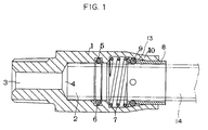
- Fig. 1 is a cross-sectional view illustrating a pipe coupling according to a first embodiment of the present invention.
- Fig. 2 is a partial cross-sectional view illustrating the relationship between an inner collar and a ball.
- Fig. 3 is a partial cross-sectional view of another example illustrating the relationship between the inner collar and the ball.
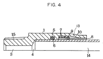
- Fig. 4 is a partial cross-sectional view illustrating a state in which a pipe body is pulled out from the pipe coupling of the present invention.
- Fig. 5 is a partial cross-sectional view of a modified example illustrating the relationship between the inner collar and an outer collar.
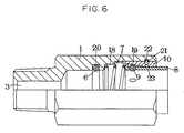
- Fig. 6 is a view illustrating a cross-section of one-half of a pipe coupling according to a second embodiment of the present invention.
- Fig. 7 is a view illustrating a cross-section of one-half of a pipe coupling according to a third embodiment of the present invention.
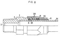
- Fig. 8 is a view illustrating a cross-section of one-half of a pipe coupling according to a fourth embodiment of the present invention.
- Fig. 9 is a view illustrating a cross-section of one-half of a conventional pipe coupling.
- Fig. 1 is a cross-sectional view illustrating a pipe coupling according to a first embodiment of the present invention.
- a female member 1 which forms a base body of the pipe coupling is provided with a through hole 2 having a large diameter, and a through hole 3 having a small diameter.
- a stepped portion 4 is formed between these through holes 2 and 3.
- the through hole 2 is provided with a groove 5 near a leading end thereof, and a seal member 6 such as an O ring is fitted into the groove 5.
- a coil spring 7 is disposed further toward an exit than the seal member 6, and an inner collar 8 made of synthetic resin, together with a pressing member, i.e., a ball 9, is disposed even further toward the exit than the coil spring 7.
- the coil spring 7, the inner collar 8 and the ball 9 are all covered by an outer collar 10.
- the collar 10 extends from and is formed integrally with the female member 1, and a leading end of the collar 10 is reduced in diameter.
- a separate outer collar may be fixed to the female member 1 by brazing or may be screwed thereto.
- the position of the outer collar 10 can be adjusted in accordance with the degree to which the outer collar 10 and the female member 1 are screwed together.
- the relationship between the inner collar 8 and the ball 9 is such that the ball 9 is fitted into the inner collar 8 as illustrated in Fig. 2.
- This structure is formed by setting the ball 9 into a mold at the time of molding the inner collar 8 so that the ball 9 can be fitted into the inner collar 8.
- a crack may be formed in the inner collar 8 at a leading end thereof.
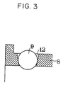
- Fig. 3 illustrates a modified example of the relationship between the inner collar 8 and the ball 9.
- a tapered hole 12 is formed in the inner collar 8, and the ball 9 is fitted into the hole 12 from an outer peripheral side of the inner collar 8.
- the outer collar 10 has an inclined surface 13 with respect to the above-described ball 9.
- the inclined surface 13 is formed such that the diameter thereof at the side of a deep portion, i.e., the portion, within the female member 1, with which a leading end of an inserted pipe body makes contact, is large.
- the inclined surface 13 causes the movement of the ball 9 to be restricted, and causes a contact force of the ball 9 with respect to a pipe body to be exhibited.
- Fig. 1 illustrates the state in which a pipe body 14 indicated by the dotted lines is inserted into the inner collar 8.
- the position of the pipe body 14 is determined by causing the leading end thereof to abut against the stepped portion 4.
- the ball 9 is pushed against the inclined surface 13 of the outer collar 10 by the coil spring 7.
- the inclined surface 13 of the outer collar 10 causes the ball 9 to press the surface of the pipe body 14.
- the ball 9 When the pipe body 14 is about to be pulled out by a stronger force, or when the pressure within the pipe body 14 becomes high, the ball 9 is pressed strongly by the inclined surface 13 of the outer collar 10 and strongly presses the surface of the pipe body 14. As a result, the ball 9 may be dug in the surface of the pipe body 14 such that the pipe body 14 can be firmly held by the ball 9.
- the ball 9 is made of any material whose hardness is larger than that of the pipe body 14.
- the pipe body 14 when the pipe body 14 is removed from the pipe coupling, a leading end of the above-described inner collar 8, which projects out from the leading end of the outer collar 10, is used. Namely, the pipe body 14 can be pulled out by pushing the leading end of the inner collar 8 in the direction of the female member 1. In other words, the inner collar 8 can be moved in the direction of the female member 1 by pushing the projected portion of the inner collar 8, thereby causing a pressing force of the ball 9 to be released.
- the female member 1 is provided with a male screw 15 at the side of the through hole 3.
- the male screw 15 is connected to an illustrated pipe body or the like.
- seal member 6 an O ring of which the cross-sectional configuration is circular, is shown herein.
- the present invention is not limited to the same, and any seal member, for example, a cross-section thereof is an L-shaped or X-shaped configuration, may be applied.
- the relationship between the inner collar 8 and the outer collar 10 does not always need to be set such that the inner collar 8 projects out from the outer collar 10, and it suffices that the inner collar 8 can be moved toward the side of the female member 1 from the outside.
- Fig. 5 is a partial cross-sectional view illustrating the example as described above. It suffices that, although the leading end of the inner collar 8 does not project out from the outer collar 10, the leading end of the inner collar 8 can be pushed by a screwdriver 16 or the like. In addition, a small hole 17 is formed in the outer collar 10, and the screwdriver 16 or the like is pushed into the small hole 17, thereby causing the inner collar 8 to be moved toward the side of the female member 1.
- Fig. 6 is a view illustrating a cross-section of one-half of a pipe coupling according to a second embodiment of the present invention.
- an inner peripheral surface of the female member 1 is formed by a plurality of stepped portions.
- the coil spring 7 is fitted into a second stepped portion 18, and the outer collar 10 is fitted into a third stepped portion 19.
- an O ring 6 is fitted into a groove 20 formed in the inner peripheral surface of the female member 1.
- an engaging member (a stop ring) 21 is fitted into a groove 22 formed in the inner peripheral surface of the third stepped portion 19 of the female member 1 and a groove 23 formed in the outer collar 10.
- Fig. 7 is a view illustrating a cross-section of one-half of a pipe coupling according to a third embodiment of the present invention.
- the seal member 6 located at the inner peripheral surface of the female member 1 is supported by a washer 24 against the seal member 6.
- Fig. 8 is a view illustrating a cross-section of one-half of a pipe coupling according to a fourth embodiment of the present invention.
- the female member 1 and the outer collar 10 are threadedly engaged with each other.
- Other structures are similar to those of the first embodiment. Namely, the female member 1 and the outer collar 10 are screwed together by means of a male screw 25 of the female member 1 and a female screw 26 of the outer collar 10. The position where the inclined portion 13 of the outer collar 10 and the ball 9 contact each other can be adjusted in accordance with the degree to which the female member 1 and the outer collar 10 are screwed together.
- each operation of connecting and removing the pipe body can be effected in the same way as the first embodiment.
Landscapes
- Engineering & Computer Science (AREA)
- General Engineering & Computer Science (AREA)
- Mechanical Engineering (AREA)
- Quick-Acting Or Multi-Walled Pipe Joints (AREA)
- Joints With Sleeves (AREA)
Applications Claiming Priority (2)
| Application Number | Priority Date | Filing Date | Title |
|---|---|---|---|
| JP5085336A JPH06272795A (ja) | 1993-03-19 | 1993-03-19 | 管継手 |
| JP85336/93 | 1993-03-19 |
Publications (1)
| Publication Number | Publication Date |
|---|---|
| EP0616165A1 true EP0616165A1 (de) | 1994-09-21 |
Family
ID=13855805
Family Applications (1)
| Application Number | Title | Priority Date | Filing Date |
|---|---|---|---|
| EP94104217A Withdrawn EP0616165A1 (de) | 1993-03-19 | 1994-03-17 | Rohrkupplung |
Country Status (2)
| Country | Link |
|---|---|
| EP (1) | EP0616165A1 (de) |
| JP (1) | JPH06272795A (de) |
Cited By (8)
| Publication number | Priority date | Publication date | Assignee | Title |
|---|---|---|---|---|
| FR2740532A1 (fr) * | 1995-10-30 | 1997-04-30 | Manuli Automobile France Sa | Raccord etanche a connexion rapide |
| GB2331341A (en) * | 1997-11-14 | 1999-05-19 | Nitto Kohki Co | Socket for pipe coupling and pipe coupling including such |
| CN102374349A (zh) * | 2010-08-13 | 2012-03-14 | 奥麦克股份公司 | 特别用于家用电器的套管式延伸件及相关家用电器 |
| CN103775774A (zh) * | 2014-01-28 | 2014-05-07 | 张颂文 | 直推连接管接头 |
| CN111156358A (zh) * | 2020-03-03 | 2020-05-15 | 许吉界 | 一种管道安装连接法兰 |
| CN113752815A (zh) * | 2021-11-10 | 2021-12-07 | 北京胜能能源科技有限公司 | 一种钢珠涨紧式锁止机构及其尺寸设计方法 |
| CN116972243A (zh) * | 2023-07-28 | 2023-10-31 | 沈阳飞机工业(集团)有限公司 | 金属导管无扩口直接快速连接方法 |
| CN120212346A (zh) * | 2025-05-27 | 2025-06-27 | 苏州罗克莱科技有限公司 | 一种海洋管道维修机械连接器 |
Families Citing this family (9)
| Publication number | Priority date | Publication date | Assignee | Title |
|---|---|---|---|---|
| KR20020078164A (ko) * | 2001-04-06 | 2002-10-18 | 김석윤 | 배관용 조인트 |
| JP4599043B2 (ja) * | 2003-09-03 | 2010-12-15 | Jfe継手株式会社 | 差込み式管継手 |
| JP4628931B2 (ja) * | 2005-11-04 | 2011-02-09 | 日東工器株式会社 | 雄雌部材アセンブリ |
| WO2012051481A1 (en) | 2010-10-15 | 2012-04-19 | Swagelok Company | Push to connect conduit fitting with ferrule |
| JP2013245744A (ja) * | 2012-05-25 | 2013-12-09 | Jfe Pipe Fitting Mfg Co Ltd | 差込式管継手 |
| WO2015061404A1 (en) * | 2013-10-24 | 2015-04-30 | Swagelok Company | Single action push to connect conduit fitting |
| EP3286476B1 (de) * | 2015-04-23 | 2019-10-02 | Swagelok Company | Steckverbindung für ein rohr |
| US10458582B2 (en) | 2015-04-23 | 2019-10-29 | Swagelok Company | Single action push to connect conduit fitting with colleting |
| EP3948042B1 (de) | 2019-04-01 | 2025-01-08 | Swagelok Company | Push-to-connect-anschlussbaugruppen für leitungen und anordnungen |
Citations (4)
| Publication number | Priority date | Publication date | Assignee | Title |
|---|---|---|---|---|
| FR706393A (fr) * | 1929-08-21 | 1931-06-23 | Accouplement rapide et automatique pour tirants, câbles métalliques, tuyaux et objets analogues | |
| US2182797A (en) * | 1938-03-15 | 1939-12-12 | Stephen V Dillon | Gripping and coupling means |
| DE8121384U1 (de) * | 1980-07-21 | 1982-02-25 | IMI Enots Ltd., Lichfield, Staffordshire | Loesbare rohrkupplung und patrone zur bildung einer solchen rohrkupplung |
| EP0156575A2 (de) * | 1984-03-13 | 1985-10-02 | Owen Walmsley | Klemme |
-
1993
- 1993-03-19 JP JP5085336A patent/JPH06272795A/ja active Pending
-
1994
- 1994-03-17 EP EP94104217A patent/EP0616165A1/de not_active Withdrawn
Patent Citations (4)
| Publication number | Priority date | Publication date | Assignee | Title |
|---|---|---|---|---|
| FR706393A (fr) * | 1929-08-21 | 1931-06-23 | Accouplement rapide et automatique pour tirants, câbles métalliques, tuyaux et objets analogues | |
| US2182797A (en) * | 1938-03-15 | 1939-12-12 | Stephen V Dillon | Gripping and coupling means |
| DE8121384U1 (de) * | 1980-07-21 | 1982-02-25 | IMI Enots Ltd., Lichfield, Staffordshire | Loesbare rohrkupplung und patrone zur bildung einer solchen rohrkupplung |
| EP0156575A2 (de) * | 1984-03-13 | 1985-10-02 | Owen Walmsley | Klemme |
Cited By (13)
| Publication number | Priority date | Publication date | Assignee | Title |
|---|---|---|---|---|
| FR2740532A1 (fr) * | 1995-10-30 | 1997-04-30 | Manuli Automobile France Sa | Raccord etanche a connexion rapide |
| WO1997016673A1 (fr) * | 1995-10-30 | 1997-05-09 | Manuli Auto France | Raccord etanche a connexion rapide |
| GB2331341A (en) * | 1997-11-14 | 1999-05-19 | Nitto Kohki Co | Socket for pipe coupling and pipe coupling including such |
| GB2331341B (en) * | 1997-11-14 | 2000-04-05 | Nitto Kohki Co | Pipe coupling and socket therefor |
| CN102374349B (zh) * | 2010-08-13 | 2015-04-08 | 奥麦克股份公司 | 特别用于家用电器的套管式延伸件及相关家用电器 |
| CN102374349A (zh) * | 2010-08-13 | 2012-03-14 | 奥麦克股份公司 | 特别用于家用电器的套管式延伸件及相关家用电器 |
| CN103775774A (zh) * | 2014-01-28 | 2014-05-07 | 张颂文 | 直推连接管接头 |
| CN103775774B (zh) * | 2014-01-28 | 2017-10-10 | 张颂文 | 直推连接管接头 |
| CN111156358A (zh) * | 2020-03-03 | 2020-05-15 | 许吉界 | 一种管道安装连接法兰 |
| CN111156358B (zh) * | 2020-03-03 | 2021-08-03 | 荆州市江汉汽车零部件制造股份有限公司 | 一种管道安装连接法兰 |
| CN113752815A (zh) * | 2021-11-10 | 2021-12-07 | 北京胜能能源科技有限公司 | 一种钢珠涨紧式锁止机构及其尺寸设计方法 |
| CN116972243A (zh) * | 2023-07-28 | 2023-10-31 | 沈阳飞机工业(集团)有限公司 | 金属导管无扩口直接快速连接方法 |
| CN120212346A (zh) * | 2025-05-27 | 2025-06-27 | 苏州罗克莱科技有限公司 | 一种海洋管道维修机械连接器 |
Also Published As
| Publication number | Publication date |
|---|---|
| JPH06272795A (ja) | 1994-09-27 |
Similar Documents
| Publication | Publication Date | Title |
|---|---|---|
| US5653480A (en) | Pipe coupling | |
| US3312484A (en) | Toggle ring tube coupling | |
| US6869109B2 (en) | Pipe joint | |
| EP1074781B1 (de) | Rohrkupplung | |
| US6186561B1 (en) | Retainer for piping connector | |
| US6991265B2 (en) | Device for gripping a pipe or bar | |
| US7798537B2 (en) | Coupling apparatus | |
| US6334634B1 (en) | Push-to-connect tubing fitting | |
| EP0425230B1 (de) | Rohrkupplung | |
| JPH0439492A (ja) | クイックコネクタ | |
| JPS6116877B2 (de) | ||
| JPH06272795A (ja) | 管継手 | |
| EP1366318A1 (de) | Kupplung zur verbindung eines rohrs oder schlauchs durch einschieben | |
| KR100245776B1 (ko) | 세경 파이프 접속용 연결구 | |
| JP2006077837A (ja) | ホース接続用のコネクタ | |
| KR100324547B1 (ko) | 퀵타입 커플링 | |
| JP2002357295A (ja) | 管継手 | |
| KR102116778B1 (ko) | 고압호스 연결용 피팅 | |
| JP4391222B2 (ja) | 管継手 | |
| WO2002046655A1 (en) | Pipe joint | |
| JPH0914555A (ja) | 管継手 | |
| KR200179786Y1 (ko) | 호스 연결구 | |
| JPH0735189Y2 (ja) | 配管端末接続構造 | |
| JP4387993B2 (ja) | 配管継手 | |
| JP3307569B2 (ja) | 伸縮可撓継手 |
Legal Events
| Date | Code | Title | Description |
|---|---|---|---|
| PUAI | Public reference made under article 153(3) epc to a published international application that has entered the european phase |
Free format text: ORIGINAL CODE: 0009012 |
|
| 17P | Request for examination filed |
Effective date: 19940317 |
|
| AK | Designated contracting states |
Kind code of ref document: A1 Designated state(s): DE FR GB |
|
| 17Q | First examination report despatched |
Effective date: 19950711 |
|
| STAA | Information on the status of an ep patent application or granted ep patent |
Free format text: STATUS: THE APPLICATION IS DEEMED TO BE WITHDRAWN |
|
| 18D | Application deemed to be withdrawn |
Effective date: 19960123 |