EP0616391A2 - Steckverbinder mit Verrieglungshebel - Google Patents
Steckverbinder mit Verrieglungshebel Download PDFInfo
- Publication number
- EP0616391A2 EP0616391A2 EP94104205A EP94104205A EP0616391A2 EP 0616391 A2 EP0616391 A2 EP 0616391A2 EP 94104205 A EP94104205 A EP 94104205A EP 94104205 A EP94104205 A EP 94104205A EP 0616391 A2 EP0616391 A2 EP 0616391A2
- Authority
- EP
- European Patent Office
- Prior art keywords
- connector housing
- male
- female
- female connector
- housing
- Prior art date
- Legal status (The legal status is an assumption and is not a legal conclusion. Google has not performed a legal analysis and makes no representation as to the accuracy of the status listed.)
- Granted
Links
- 238000003780 insertion Methods 0.000 claims description 18
- 230000037431 insertion Effects 0.000 claims description 18
- 230000008859 change Effects 0.000 abstract description 2
- 229920003002 synthetic resin Polymers 0.000 description 4
- 239000000057 synthetic resin Substances 0.000 description 4
- 239000000463 material Substances 0.000 description 3
- 230000008901 benefit Effects 0.000 description 2
- 238000010276 construction Methods 0.000 description 2
- 230000005489 elastic deformation Effects 0.000 description 2
- 238000012986 modification Methods 0.000 description 2
- 230000004048 modification Effects 0.000 description 2
- 230000009471 action Effects 0.000 description 1
- 230000007246 mechanism Effects 0.000 description 1
- 238000000034 method Methods 0.000 description 1
- 230000005405 multipole Effects 0.000 description 1
- 230000008569 process Effects 0.000 description 1
Images


Classifications
-
- H—ELECTRICITY
- H01—ELECTRIC ELEMENTS
- H01R—ELECTRICALLY-CONDUCTIVE CONNECTIONS; STRUCTURAL ASSOCIATIONS OF A PLURALITY OF MUTUALLY-INSULATED ELECTRICAL CONNECTING ELEMENTS; COUPLING DEVICES; CURRENT COLLECTORS
- H01R13/00—Details of coupling devices of the kinds covered by groups H01R12/70 or H01R24/00 - H01R33/00
- H01R13/62—Means for facilitating engagement or disengagement of coupling parts or for holding them in engagement
- H01R13/629—Additional means for facilitating engagement or disengagement of coupling parts, e.g. aligning or guiding means, levers, gas pressure electrical locking indicators, manufacturing tolerances
- H01R13/62933—Comprising exclusively pivoting lever
- H01R13/62955—Pivoting lever comprising supplementary/additional locking means
-
- H—ELECTRICITY
- H01—ELECTRIC ELEMENTS
- H01R—ELECTRICALLY-CONDUCTIVE CONNECTIONS; STRUCTURAL ASSOCIATIONS OF A PLURALITY OF MUTUALLY-INSULATED ELECTRICAL CONNECTING ELEMENTS; COUPLING DEVICES; CURRENT COLLECTORS
- H01R13/00—Details of coupling devices of the kinds covered by groups H01R12/70 or H01R24/00 - H01R33/00
- H01R13/62—Means for facilitating engagement or disengagement of coupling parts or for holding them in engagement
- H01R13/629—Additional means for facilitating engagement or disengagement of coupling parts, e.g. aligning or guiding means, levers, gas pressure electrical locking indicators, manufacturing tolerances
- H01R13/62933—Comprising exclusively pivoting lever
- H01R13/62938—Pivoting lever comprising own camming means
Definitions
- This invention relates to a connector, and more particularly to a connector of the type having a connection effected using a lever.
- Connectors utilizing levers have an advantage in that connection and disconnection can be effected with a small force. This has been applied particularly to multi-pole connectors.
- the fundamental construction of such connectors is known and described in Japanese Patent Unexamined Publication No. 4-62772 as follows.
- a number of male terminals are provided in a male connector housing serving as a receiving connector housing.
- a number of female terminals are provided in a female connector housing to be inserted into the male terminals.
- a lever with cam grooves for effecting leverage is pivotally mounted on the male connector housing, and engagement projections are provided on a central portion of a lower portion of a cover mounted on the female connector housing.
- the engagement projections of the cover are respectively engaged in the cam grooves of the lever for connecting the two connector housings together.
- the lever is pivotally movable.
- the cover and the female connector housing are inserted into the male connector housing by a cam action of the cam grooves so that the male and female terminals of the two connector housings are connected together against a mechanical insertion resistance, thus completing the connection of the two connector housings.
- the group of terminals provided in each connector housing are not always of the same type and are not always arranged and distributed uniformly.
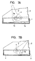
- a so-called hybrid type is shown in Fig. 7A in which a smaller number of power terminals 1a and a larger number of signal terminals 1b are provided in a male connector housing 1.
- a large unbalance of a mechanical insertion resistance may occur between the right and the left regions of the group of terminals 1a, 1b.
- the female connector housing 2 is inserted in a tilted manner, as shown in Fig. 7A, so that the opposite end edges of the female connector housing 2 interfere with an inner surface of the male connector housing 1 at two points, which are designated, respectively, by reference characters X and Y in Fig. 7B.
- the female connector housing 2 is generally made of a synthetic resin material.
- An engagement projection 4 engaged in a cam groove 3a of a lever 3 is provided at a central position in the X-Y direction. Therefore, the female connector housing 2 is elastically deformed by a pressing force applied to the engagement projection 4 through leverage of the lever 3 such that the lower surface of the female connector housing 2 bulges between the two points X and Y. This bulged portion abuts against the bottom surface of the male connector housing 1 so that the female connector housing 2 cannot be further inserted. As a result, the female connector housing 2 remains tilted relative to the male connector housing 1. This may cause problems because the connection of the terminals is incomplete, which therefore invites incomplete contact.
- An object of the present invention is to provide a connector where even if there is an unbalance in insertion resistance, the two connector housings are prevented from being inserted in a tilted manner relative to each other, thereby preventing incomplete contact of terminals.
- the present invention provides a lever-type connector having a lever that is pivotally mounted on one of two connector housings of the connector. The connection and disconnection of the connector are effected by the lever. A recessed portion is formed in at least one of opposed surfaces of the two connector housings except for marginal portions such that the opposed surfaces contact each other when the connector is fully connected.
- the opposed surface of the first connector housing interferes at its opposite end edges with improper portions of the second connector housing so that the first connector housing is elastically deformed and bulged at a central portion of the opposed surface. Even at this time, a gap due to the recessed portion is secured between the bulged opposed surface and the opposed surface of the second connector housing.
- the first connector housing is further inserted in an elastically deformed condition. At this time, the first connector housing slides at the opposite end edges of the opposed surface to change its posture. As a result, the two connector housings are connected together in a proper posture without tilting such that the opposite end edges of the opposed surfaces of the two connector housings are in contact with each other.
- the two connector housings are connected together in the proper posture without tilting, and therefore, an advantage is achieved such that incomplete contact of the terminals is prevented.
- the lever-type connector of the present invention comprises a male connector housing 10, a female connector housing 20, and a lever 30.
- the male connector housing 10 is made of a synthetic resin material and has a hood portion 11 into which the female connector housing 20 is tightly fitted.
- the hood portion 11 has a uniform rectangular horizontal cross-section from its opening to its inner bottom surface.
- a plurality of male terminals 12 are provided, including power terminals 12a of a relatively large size and signal terminals 12b of a relatively small size.
- the power terminals 12a are provided at a right region of the inner bottom surface of the hood portion 11 in the direction of the long side of the inner bottom surface, and the signal terminals 12b are provided at the left region of the inner bottom surface.
- Lever support shafts 13 are respectively formed on central portions of the opposite side surfaces of the hood portion 11.
- a lever 30, of a synthetic resin and having two legs 31, is pivotally mounted on the lever support shafts 13 at two legs 31.
- Each leg 31 has an arcuate cam groove 32.
- the lever support shafts 13 are inwardly disposed of the arc of the cam groove 32.
- the female connector housing 20 is made of a synthetic resin material and has a size and shape that can be tightly fitted in the hood portion 11 of the male connector housing 10.
- Female terminals (not shown), to be respectively connected to the male terminals 12, are provided in the portion of the female connector housing to be fitted in the hood portion 11.
- the female connector housing 20 has a cover 21 that is exposed to the exterior of the hood portion 11 when the female connector housing 20 is fitted in the male connector housing 10.
- Cam reception projections 22 are respectively formed on opposite side surfaces of the cover 21 to be respectively received in the cam grooves 32 of the legs 31. The cam reception projections 22 cooperate with the lever 30 to connect the male and female connector housings 10 and 20 together.
- the cam reception projections 22 elastically deform the two legs 31 of the lever 30 to urge the two legs 31 away from each other.
- the cam reception projections 22 are respectively received in the cam grooves 32, thus providing a connection condition.
- the engagement position between the cam reception projection 22 and the cam groove 32 in the direction of the length of the cam groove 32 is moved relative to the lever support shaft 13 in a direction to reduce the distance between this engagement position and the lever support shaft 13.
- the female connector housing 20 is inserted deep into the hood portion 11 against the sliding resistance between the male and female connector housings 10 and 20 and the fitting resistances between the male and female terminals.
- Fig. 1B shows a partial state of connection between the male connector housing 10 and the female connector housing 20.
- Fig. 1C shows a fully connected state when the lever 30 is fully rotated.
- the male connector housing 10 is provided with means for ensuring a positive connection between the male and female connector housings 10 and 20 as will now be described.
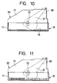
- Slightly-raised step portions 15 are respectively formed on the four corner portions of the inner bottom surface of the hood portion 11.
- the other portion of the inner bottom surface of the hood portion 11 provides a recessed portion 16 having a wider area and smaller height than the step portions 15. For example, when the dimension of the long side of the inner bottom surface of the hood portion 11 is approximately 10 cm, the difference in height between the step portion 15 and the recessed portion 16 is approximately 0.5 ⁇ 0.7 mm.
- the female connector housing 20 When the female connector housing 20 is fitted into the hood portion 11 by pivotally moving the lever 30, the female connector housing 20 is brought into a tilted posture relative to the male connector housing 10. This is because the fitting resistances of the male power terminals 12a and the male signal terminals 12b relative to the female terminals are different from each other because of the difference in distribution densities between the power terminals 12a and the signal terminals 12b.
- one of the opposite ends (the left end in Fig. 1B) of the female connector housing 20 is abutted against the upper surfaces of the step portions 15.
- the other end (the right end in Fig. 1B) interferes with a portion of the inner wall surface of the hood portion 11 slightly above the step portions 15.
- the insertion of the female connector housing 20 is then in a condition as shown in Fig. 1B.
- the central portion of the female connector housing 20 is elastically deformed to bulge downwardly by a pressing force applied through the engagement between the cam grooves 32 of the lever 30 and the cam reception projections 22.
- the force obtained by combining a resiliently-restoring force (increasing with the increase flexing of the female connector housing 20) with the insertion force of the lever 30 becomes generally equal to the insertion resistance obtained by combining the fitting resistances between the male and female terminals with the frictional resistance at the area of contact between the male and female connector housings 10 and 20.
- a slight gap S is provided for allowing a further elastic deformation or further insertion of the female connector housing 20 between the bulged portion of the female connector housing 20 and the recessed portion 16 of the hood portion 11.
- the female connector housing 20 is further elastically deformed to narrow the gap S between the bulged portion and the recessed portion 16 of the hood portion 11.
- the combined force of the increased resiliently-restoring force of the female connector housing 20 and the insertion force of the lever 30 overcomes the above insertion resistance so that the female connector housing 20 slides on the contact areas (i.e., on the step portions 15 and on the inner wall surface), thereby connecting the female connector housing 20 into a proper posture.
- the female connector housing 20 is inserted to such an extent that the opposite ends of the female connector housing 20, in the direction of the length of the female connector housing 20, are abutted against the step portions 15.
- the male terminals 12 and the female terminals are therefore completely connected together to thereby prevent imperfect contact of the terminals caused by the tilted fitting of the male and female connector housings 10 and 20 relative to each other.
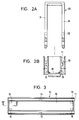
- Figs. 2A-2B show the lever 30 in a disassembled condition with respect to the hood portion 11.
- Figs. 3 and 4 show different views of the male connector housing with the terminals omitted.
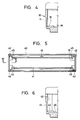
- the opposite inner side wall surfaces of a hood portion 41 of a male connector housing 40 provide guide grooves 42 at opposite ends of the hood portion 41.
- a female connector housing (not shown in Figs. 5 and 6) is inserted into the hood portion 41, guide ribs formed on the female connector housing are fitted in the guide grooves 42, respectively, so that the female connector housing is guided to keep a proper posture without being tilted relative to the hood portion 41.
- Bottom surfaces of the guide grooves formed in the hood portion 41 are constituted by raised step portions 45 slightly higher than an inner bottom surface of the hood portion 41. Therefore, the inner bottom surface of the hood portion 41 provides a recessed portion 46 lower than the step portions 45.
- the guide ribs are fitted in the guide grooves, and by doing so, the female connector housing can be inserted into the hood portion 41 without being tilted relative to the male connector housing 40.
- the female connector housing interferes with an inner wall surface of the hood portion 41 with one end abutted against the step portions 45 so that the female connector housing has a tilted posture.
- the inner bottom surface of the hood portion 41 is formed by the recessed portion 46 lower than the step portions 45, and therefore, even when the female connector housing is elastically deformed to be bulged at its lower surface, a gap for allowing a further elastic deformation and a further insertion of the female connector housing is provided between this bulged portion and the recessed portion 46.
- the female connector housing is finally fitted in the male connector housing in the proper posture so that the complete connection between the male and female terminals is achieved.
Landscapes
- Details Of Connecting Devices For Male And Female Coupling (AREA)
Applications Claiming Priority (2)
| Application Number | Priority Date | Filing Date | Title |
|---|---|---|---|
| JP1993018643U JP2595864Y2 (ja) | 1993-03-19 | 1993-03-19 | レバー式コネクタ |
| JP18643/93 | 1993-03-19 |
Publications (3)
| Publication Number | Publication Date |
|---|---|
| EP0616391A2 true EP0616391A2 (de) | 1994-09-21 |
| EP0616391A3 EP0616391A3 (de) | 1995-06-28 |
| EP0616391B1 EP0616391B1 (de) | 1998-01-28 |
Family
ID=11977293
Family Applications (1)
| Application Number | Title | Priority Date | Filing Date |
|---|---|---|---|
| EP94104205A Expired - Lifetime EP0616391B1 (de) | 1993-03-19 | 1994-03-17 | Steckverbinder mit Verrieglungshebel |
Country Status (4)
| Country | Link |
|---|---|
| US (1) | US5441420A (de) |
| EP (1) | EP0616391B1 (de) |
| JP (1) | JP2595864Y2 (de) |
| DE (1) | DE69408184T2 (de) |
Cited By (2)
| Publication number | Priority date | Publication date | Assignee | Title |
|---|---|---|---|---|
| EP0843386A1 (de) * | 1996-08-08 | 1998-05-20 | Sumitomo Wiring Systems, Ltd. | Steckverbinder mit Hebel |
| WO2009002493A3 (en) * | 2007-06-26 | 2009-10-15 | Tyco Electronics Corporation | Electrical connector assembly for use with a blister pack |
Families Citing this family (7)
| Publication number | Priority date | Publication date | Assignee | Title |
|---|---|---|---|---|
| DE69423372T2 (de) * | 1993-01-06 | 2000-10-26 | Sumitomo Wiring Systems, Ltd. | Steckverbinder mit Verriegelungshebel |
| JP3472666B2 (ja) * | 1996-07-24 | 2003-12-02 | 矢崎総業株式会社 | コネクタ |
| JPH1131551A (ja) * | 1997-07-09 | 1999-02-02 | Yazaki Corp | レバー嵌合式コネクタ |
| US5938458A (en) * | 1998-06-17 | 1999-08-17 | Molex Incorporated | Lever type electrical connector |
| EP1037326A3 (de) * | 1999-03-08 | 2001-02-07 | The Whitaker Corporation | Hebelbetätigter elektrischer Verbinder |
| JP5753465B2 (ja) * | 2011-09-12 | 2015-07-22 | 矢崎総業株式会社 | コネクタ係合体 |
| JP5935750B2 (ja) * | 2013-04-26 | 2016-06-15 | 住友電装株式会社 | レバー式コネクタ |
Family Cites Families (6)
| Publication number | Priority date | Publication date | Assignee | Title |
|---|---|---|---|---|
| NL137273B (de) * | 1966-04-08 | |||
| DE3527916A1 (de) * | 1985-08-03 | 1987-02-12 | Cannon Electric Gmbh | Elektrische steckerkupplung |
| US5135410A (en) * | 1990-05-30 | 1992-08-04 | Sumitomo Wiring Systems, Ltd. | Electric connector assembly |
| JP2971531B2 (ja) * | 1990-06-29 | 1999-11-08 | 住友電装株式会社 | コネクタの結合構造 |
| JPH0810611B2 (ja) * | 1990-10-02 | 1996-01-31 | 山一電機工業株式会社 | コネクタ |
| US5230635A (en) * | 1991-06-25 | 1993-07-27 | Yazaki Corporation | Connector with lever |
-
1993
- 1993-03-19 JP JP1993018643U patent/JP2595864Y2/ja not_active Expired - Lifetime
-
1994
- 1994-03-17 US US08/214,238 patent/US5441420A/en not_active Expired - Lifetime
- 1994-03-17 EP EP94104205A patent/EP0616391B1/de not_active Expired - Lifetime
- 1994-03-17 DE DE69408184T patent/DE69408184T2/de not_active Expired - Lifetime
Cited By (4)
| Publication number | Priority date | Publication date | Assignee | Title |
|---|---|---|---|---|
| EP0843386A1 (de) * | 1996-08-08 | 1998-05-20 | Sumitomo Wiring Systems, Ltd. | Steckverbinder mit Hebel |
| US5888081A (en) * | 1996-08-08 | 1999-03-30 | Sumitomo Wiring Systems Inc. | Lever connector |
| WO2009002493A3 (en) * | 2007-06-26 | 2009-10-15 | Tyco Electronics Corporation | Electrical connector assembly for use with a blister pack |
| US7699174B2 (en) | 2007-06-26 | 2010-04-20 | Tyco Electronics Corporation | Electrical connector interfaced with conductive ink on a cardboard substrate |
Also Published As
| Publication number | Publication date |
|---|---|
| DE69408184T2 (de) | 1998-05-14 |
| JPH0672174U (ja) | 1994-10-07 |
| JP2595864Y2 (ja) | 1999-06-02 |
| EP0616391B1 (de) | 1998-01-28 |
| DE69408184D1 (de) | 1998-03-05 |
| US5441420A (en) | 1995-08-15 |
| EP0616391A3 (de) | 1995-06-28 |
Similar Documents
| Publication | Publication Date | Title |
|---|---|---|
| US10566735B2 (en) | Connector | |
| US6183277B1 (en) | Lever fitting-type connector | |
| EP0803937B1 (de) | Verbinder mit Trägheitsverriegelung | |
| JP3949064B2 (ja) | 電気コネクタ | |
| US6203385B1 (en) | Electrical contact | |
| US5938470A (en) | Half-fitting prevention connector | |
| US6623316B1 (en) | Electrical connector having improved features regarding normal force required for effectively engaging a printed board with the electrical connector | |
| USRE34539E (en) | Electrical connector | |
| JPH03116672A (ja) | 電気コネクタ | |
| US5584721A (en) | Connector | |
| EP0616391B1 (de) | Steckverbinder mit Verrieglungshebel | |
| JP3442577B2 (ja) | フードアッシーのコネクタへの組付方法および同組付構造 | |
| EP1115181A1 (de) | Elektrischer Verbinder | |
| EP0448083B1 (de) | Vorrichtung zum Feststellen des Eingriffs eines Verbinders | |
| JPH0216542Y2 (de) | ||
| CN101740946A (zh) | 连接器 | |
| US6224414B1 (en) | Half-fitting prevention connector | |
| JP3218155B2 (ja) | カム部材付きコネクタ | |
| US6224403B1 (en) | Lever-fitting type connector | |
| US7066747B2 (en) | Connector | |
| US6250937B1 (en) | Lever fitting-type connector | |
| US5915996A (en) | Assembly of plug and cap electric connectors | |
| US5427539A (en) | Lever type connector | |
| US6247945B1 (en) | Lever fitting connector | |
| JP2001057269A (ja) | コネクタ |
Legal Events
| Date | Code | Title | Description |
|---|---|---|---|
| PUAI | Public reference made under article 153(3) epc to a published international application that has entered the european phase |
Free format text: ORIGINAL CODE: 0009012 |
|
| AK | Designated contracting states |
Kind code of ref document: A2 Designated state(s): DE FR GB |
|
| PUAL | Search report despatched |
Free format text: ORIGINAL CODE: 0009013 |
|
| AK | Designated contracting states |
Kind code of ref document: A3 Designated state(s): DE FR GB |
|
| 17P | Request for examination filed |
Effective date: 19950726 |
|
| 17Q | First examination report despatched |
Effective date: 19960322 |
|
| GRAG | Despatch of communication of intention to grant |
Free format text: ORIGINAL CODE: EPIDOS AGRA |
|
| GRAG | Despatch of communication of intention to grant |
Free format text: ORIGINAL CODE: EPIDOS AGRA |
|
| GRAH | Despatch of communication of intention to grant a patent |
Free format text: ORIGINAL CODE: EPIDOS IGRA |
|
| GRAH | Despatch of communication of intention to grant a patent |
Free format text: ORIGINAL CODE: EPIDOS IGRA |
|
| GRAA | (expected) grant |
Free format text: ORIGINAL CODE: 0009210 |
|
| AK | Designated contracting states |
Kind code of ref document: B1 Designated state(s): DE FR GB |
|
| REF | Corresponds to: |
Ref document number: 69408184 Country of ref document: DE Date of ref document: 19980305 |
|
| ET | Fr: translation filed | ||
| PLBE | No opposition filed within time limit |
Free format text: ORIGINAL CODE: 0009261 |
|
| STAA | Information on the status of an ep patent application or granted ep patent |
Free format text: STATUS: NO OPPOSITION FILED WITHIN TIME LIMIT |
|
| 26N | No opposition filed | ||
| REG | Reference to a national code |
Ref country code: GB Ref legal event code: IF02 |
|
| PGFP | Annual fee paid to national office [announced via postgrant information from national office to epo] |
Ref country code: GB Payment date: 20020320 Year of fee payment: 9 |
|
| PG25 | Lapsed in a contracting state [announced via postgrant information from national office to epo] |
Ref country code: GB Free format text: LAPSE BECAUSE OF NON-PAYMENT OF DUE FEES Effective date: 20030317 |
|
| GBPC | Gb: european patent ceased through non-payment of renewal fee |
Effective date: 20030317 |
|
| PGFP | Annual fee paid to national office [announced via postgrant information from national office to epo] |
Ref country code: FR Payment date: 20110317 Year of fee payment: 18 |
|
| PGFP | Annual fee paid to national office [announced via postgrant information from national office to epo] |
Ref country code: DE Payment date: 20110309 Year of fee payment: 18 |
|
| REG | Reference to a national code |
Ref country code: FR Ref legal event code: ST Effective date: 20121130 |
|
| REG | Reference to a national code |
Ref country code: DE Ref legal event code: R119 Ref document number: 69408184 Country of ref document: DE Effective date: 20121002 |
|
| PG25 | Lapsed in a contracting state [announced via postgrant information from national office to epo] |
Ref country code: FR Free format text: LAPSE BECAUSE OF NON-PAYMENT OF DUE FEES Effective date: 20120402 |
|
| PG25 | Lapsed in a contracting state [announced via postgrant information from national office to epo] |
Ref country code: DE Free format text: LAPSE BECAUSE OF NON-PAYMENT OF DUE FEES Effective date: 20121002 |