EP0616436B1 - Erdempfangstation für Satellitensignale - Google Patents
Erdempfangstation für Satellitensignale Download PDFInfo
- Publication number
- EP0616436B1 EP0616436B1 EP94104219A EP94104219A EP0616436B1 EP 0616436 B1 EP0616436 B1 EP 0616436B1 EP 94104219 A EP94104219 A EP 94104219A EP 94104219 A EP94104219 A EP 94104219A EP 0616436 B1 EP0616436 B1 EP 0616436B1
- Authority
- EP
- European Patent Office
- Prior art keywords
- frequency
- receiver
- receivers
- signals
- local oscillator
- Prior art date
- Legal status (The legal status is an assumption and is not a legal conclusion. Google has not performed a legal analysis and makes no representation as to the accuracy of the status listed.)
- Expired - Lifetime
Links
- 230000009977 dual effect Effects 0.000 claims description 5
- 230000011664 signaling Effects 0.000 claims description 2
- 238000010586 diagram Methods 0.000 description 4
- 238000000926 separation method Methods 0.000 description 2
- 241000283014 Dama Species 0.000 description 1
- 239000013078 crystal Substances 0.000 description 1
- JNSGIVNNHKGGRU-JYRVWZFOSA-N diethoxyphosphinothioyl (2z)-2-(2-amino-1,3-thiazol-4-yl)-2-methoxyiminoacetate Chemical compound CCOP(=S)(OCC)OC(=O)C(=N/OC)\C1=CSC(N)=N1 JNSGIVNNHKGGRU-JYRVWZFOSA-N 0.000 description 1
Images

Classifications
-
- H—ELECTRICITY
- H04—ELECTRIC COMMUNICATION TECHNIQUE
- H04B—TRANSMISSION
- H04B7/00—Radio transmission systems, i.e. using radiation field
- H04B7/14—Relay systems
- H04B7/15—Active relay systems
- H04B7/185—Space-based or airborne stations; Stations for satellite systems
- H04B7/1851—Systems using a satellite or space-based relay
- H04B7/18517—Transmission equipment in earth stations
-
- H—ELECTRICITY
- H04—ELECTRIC COMMUNICATION TECHNIQUE
- H04W—WIRELESS COMMUNICATION NETWORKS
- H04W4/00—Services specially adapted for wireless communication networks; Facilities therefor
- H04W4/18—Information format or content conversion, e.g. adaptation by the network of the transmitted or received information for the purpose of wireless delivery to users or terminals
-
- H—ELECTRICITY
- H04—ELECTRIC COMMUNICATION TECHNIQUE
- H04W—WIRELESS COMMUNICATION NETWORKS
- H04W84/00—Network topologies
- H04W84/02—Hierarchically pre-organised networks, e.g. paging networks, cellular networks, WLAN [Wireless Local Area Network] or WLL [Wireless Local Loop]
- H04W84/04—Large scale networks; Deep hierarchical networks
- H04W84/06—Airborne or Satellite Networks
-
- H—ELECTRICITY
- H04—ELECTRIC COMMUNICATION TECHNIQUE
- H04W—WIRELESS COMMUNICATION NETWORKS
- H04W88/00—Devices specially adapted for wireless communication networks, e.g. terminals, base stations or access point devices
- H04W88/02—Terminal devices
- H04W88/04—Terminal devices adapted for relaying to or from another terminal or user
Definitions
- This invention relates to an earth-based receiving station for receiving radio signals from a satellite relay station.
- the control station assigns a communication channel in accordance to access demand from an earth-based transmitting station.
- a CSC common signalling channel
- the CSC is continually transmitted from the control station.
- Earth-based transmitting stations transmit access demand signals to the control station by CSC in the up-linked channels.
- Earth-based receiving stations in the system are listening CSC transmitted from the control station, and when the control station assigns a receiving channel by CSC to a receiving station, the receiving station tunes a channel receiver frequency to the assigned channel.
- All the communication channels are transmitted in burst type waves.
- Fig. 2 illustrate a block diagram of such receiving station of a prior art.
- Radio frequency signals received by an antenna 1 are converted to first intermediate frequency signals by a first frequency converter 2.
- the first intermediate frequency signals from the converter 2 are supplied through a distributor 3 to a control receiver 5 and a channel receiver 6.
- the control receiver 5 receives the CSC, phase-locks a VCO 44 to the CSC carrier frequency, and delivers output of the VCO 44 as a first local oscillator frequency to the converter 2.
- a phase-lock loop for the VCO 44 is a closed circuit comprising VCO 44, first frequency converter 2, second frequency converter 40-5, second intermediate frequency amplifier 41-5, demodulator 42-5, low-pass-filter 43, VCO 44.
- Frequency synthesizer 48-5 supplies a second local oscillator frequency to the second frequency converter 40-5.
- An amplitude level at an output of the second intermediate frequency amplifier 41-5 is detected by a level detector 45.
- the detected level is supplied to the converter 2 for feed-back controlling gain of the converter 2.
- the first intermediate frequency signals are supplied to the channel receiver 6, and a receiving frequency of a channel receiver is determined by the second local oscillator frequency which is supplied from a synthesizer 48-6.
- the channel receiver 6 is listening CSC, and when the channel receiver 6 receives a command on CSC for assigning a channel frequency, this command is demodulated by a demodulator 42-6, is decoded by a decoder in a data processor 46, and controls a logic 47-6 in accordance with the assigned channel.
- the logic 47-6 changes output frequency of the synthesizer 48-6 to generate a second local oscillator frequency to tune for receiving the assigned channel frequency.
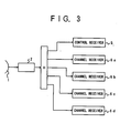
- plural channel receivers 6 are provided as shown in Fig. 3.
- EP-A-324 363 discloses a demand assignment multiple access control system for an SCPC satellite communication system with first and second control stations which independently perform centralized DAMA control through corresponding CSC.
- an important object of the invention is to eliminate the vulnerability of the prior art, and materialize an earth-based receiving station in which a standby spare of the control receiver is provided, and the standby spare of the control receiver is operating as a channel receiver in the station as long as there is no trouble in the control receiver of current use.
- Another object of this invention is to provide means for instantly converting the standing spare of the control receiver to a control receiver of current use.
- At least two receivers are provided and one of the receivers is designated to operate as a control receiver, and other receivers are designated to receive communication channels.
- an earth-based receiving station comprises:
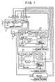
- Fig. 1 shows a block diagram of an embodiment of this invention.
- Fig. 2 shows a block diagram of an earth-based receiving station of a prior art.
- Fig. 3 shows another block diagram of an earth-based receiving station of a prior art.
- FIG. 1 there is shown an embodiment of this invention.
- the same numerals in Fig. 1 and Fig. 2 indicate the same or the corresponding parts.
- the first frequency converter 2 of the present invention comprises a low noise amplifier 20 for amplifying radio frequency signals received at the antenna 1, a first mixer 21, and a broad band first intermediate frequency amplifier 22.
- Output of the converter 2 is supplied through a distributor 3 to receivers 4a, 4b, and 4c.
- the synthesizer 48-4a is controlled to generate a second local oscillator frequency to tune to the CSC frequency.
- the control is delivered through the terminal equipment 7a, the data processor 46-4a, and the logic 47-4a.
- this second local oscillator frequency is F 2p .
- the demodulator 42 of a receiver 4 is a demodulator for PSK modulated signals, and generater a phase error at a frequency F 2 in equation(1).
- the phase error output is delivered to the low-pass-filter 43-4a.
- a selector 8a connects output of the VCO 44-4a to the converter 2
- a selector 8b connects output of the level detector 45-4a to the converter 2.
- a phase-lock loop is closed from VCO 44-4a, mixer 21, second frequency converter 40-4a, second intermediate frequency amplifier 41-4a, demodulator 42-4a, low-pass-filter 43-4a, to the VCO, and a negative-feedback-control loop is closed from level detector 45-4a, first intermediate frequency amplifier 22, second frequency converter 40-4a, second intermediate amplifier 41-4a, to the level detector 45-4a.
- first intermediate frequency signals with a suitable amplitude is supplied to receivers 4b and 4c.
- the synthesizer 48-6 is controlled to tune to CSC frequency, through the terminal equipment 7c, the data processor 46-4c, and the logic 47-4b.
- the synthesizer 48-4b is controlled to tune to CSC, but demodulated signals are ignored in the data processor 46-4b, as long as the receiver 4c is listening CSC.
- the message is demodulated by the demodulator 42-4c.
- the data processor 46-4c decodes the message and controls the synthesizer 48-4c to tune to the assigned channel frequency.
- the dual purpose receiver 4b comes to operate as another channel receiver and listens CSC.
- the host computer connects output of VCO 44-4b to the first mixer 21 through the selector 8b, and connects output of the level detector 45-4b to the first intermediate frequency amplifier 22 through the selector 8b.
- the receiver 4a can still be used as a channel receiver, and the trouble in the receiver 4a has no harm on the earth-based receiving station.
- the receiver 4c in Fig. 1 is omitted, and the receiver 4a is used as a control receiver while the receiver 4b is used as a channel receiver.
- the control receiver has a trouble and the trouble is in the VCO 44-4a
- the receiver 4a is used as a channel receiver and the receiver 4b is used as a control receiver.
Landscapes
- Engineering & Computer Science (AREA)
- Physics & Mathematics (AREA)
- Astronomy & Astrophysics (AREA)
- Aviation & Aerospace Engineering (AREA)
- General Physics & Mathematics (AREA)
- Computer Networks & Wireless Communication (AREA)
- Signal Processing (AREA)
- Radio Relay Systems (AREA)
Claims (3)
- Erdempfangsstation zum Empfangen von Funksignalen von einer Satelliten-Relaisstation, mit:gekennzeichnet durch:einem ersten Frequenzwandler (2) zum Umwandeln von Funkfrequenzsignalen von einer Satelliten-Relaisstation in entsprechende Signale in einem ersten Zwischenfrequenzband;mindestens zwei Empfänger (4a, 4b), wobei jeder Empfänger als ein Steuerempfänger oder als ein Kanalempfänger verwendbar ist, der Steuerempfänger einen gemeinsamen Signalisierungskanal (CSC) übertragen in einem Ein-Kanalpro-Träger-System (SCPC) in einer Satellitenkommunikation empfängt, eine mit der CSC-Trägerfrequenz phasensynchronisierte erste Lokaloszillatorfrequenz erzeugt, und die erste Lokaloszillatorfrequenz an den ersten Frequenzwandler (2) liefert; undeine Einrichtung zum Verwenden eines der Empfänger als den Steuerempfänger und des anderen Empfängers bzw. der Empfänger als den bzw. die Kanalempfänger.
- Erdempfangsstation nach Anspruch 1, wobei der Zwei-Zweck-Empfänger (4) aufweist:einen zweiten Frequenzwandler (40-4) zum Umwandeln der aus dem ersten Frequenzwandler (2) über einen Verteiler (3) gelieferten ersten Zwischenfrequenzsignale in Signale in einem zweiten Zwischenfrequenzband mittels einer zweiten Lokaloszillatorfrequenz,einen zweiten Zwischenfrequenzverstärker (41-4) mit einer vorbestimmten Bandbreite zum Verstärken zweiter Zwischenfrequenzsignale aus dem zweiten Frequenzwandler (40-4),einen Demodulator (42-4) zum Demodulieren von Signalen aus dem zweiten Zwischenfrequenzverstärker (41-4),eine Einrichtung zum Steuern der ersten von einem VCO (44-4) erzeugten Lokaloszillatorfrequenz mit einem in dem Demodulator (42-4) detektierten Phasenfehlersignal,einen Pegeldetektor (45-4) zum Detektieren eines Amplitudenpegels des Ausgangssignals des zweiten Zwischenfrequenzverstärkers.einen Datenprozessor (46-4) zum Dekodieren von Signalen aus dem Demodulator (42-4),einen Frequenzsynthesizer (48-4) zum Erzeugen der zweiten Lokaloszillatorfrequenz, undeine Einrichtung (47-4) zum Einstellen des Frequenzsynthesizers (48-4) durch den Datenprozessor (46-4), um eine selektierte zweite Lokaloszillatorfrequenz zu erzeugen.
- Erdempfangsstation nach Anspruch 1 oder 2, wobei die Einrichtung zum Verwenden eines von den Empfängern als Steuerempfänger und des anderen Empfängers bzw. der Empfänger als den bzw. die Kanalempfänger aufweist:eine Einrichtung zum Einstellen des Synthesizers (48-4a) in einem ersten Zwei-Zweck-Empfänger (4a) derart, daß er eine zweite Lokaloszillatorfrequenz zur Abstimmung auf die CSC-Trägerfrequenz erzeugt,einen ersten Selektor (8a) zum Verbinden des VCO-Ausgangs des ersten Zwei-Zweck-Empfängers (4a) mit dem ersten Frequenzwandler (2), undeinen zweiten Selektor (8b) zum Verbinden des Pegeldetektorausgangs des ersten Zwei-Zweck-Empfängers (4a) mit dem ersten Frequenzwandler (2).
Applications Claiming Priority (3)
| Application Number | Priority Date | Filing Date | Title |
|---|---|---|---|
| JP5999793 | 1993-03-19 | ||
| JP59997/93 | 1993-03-19 | ||
| JP5999793 | 1993-03-19 |
Publications (2)
| Publication Number | Publication Date |
|---|---|
| EP0616436A1 EP0616436A1 (de) | 1994-09-21 |
| EP0616436B1 true EP0616436B1 (de) | 1999-08-18 |
Family
ID=13129322
Family Applications (1)
| Application Number | Title | Priority Date | Filing Date |
|---|---|---|---|
| EP94104219A Expired - Lifetime EP0616436B1 (de) | 1993-03-19 | 1994-03-17 | Erdempfangstation für Satellitensignale |
Country Status (5)
| Country | Link |
|---|---|
| US (1) | US5483662A (de) |
| EP (1) | EP0616436B1 (de) |
| CN (1) | CN1052590C (de) |
| AU (1) | AU669041B2 (de) |
| DE (1) | DE69420066T2 (de) |
Families Citing this family (5)
| Publication number | Priority date | Publication date | Assignee | Title |
|---|---|---|---|---|
| DE4434903A1 (de) * | 1994-09-29 | 1996-04-11 | Hirschmann Richard Gmbh Co | Schaltungsanordnung für die Satellitenkommunikation |
| JPH1051343A (ja) * | 1996-08-06 | 1998-02-20 | Fujitsu Ltd | 信号受信装置及び信号受信システム |
| DE29710331U1 (de) * | 1997-06-13 | 1997-08-14 | TechniSat Digital GmbH, 01462 Mobschatz | Satellitenübertragungssystem zur digitalen Datenübertragung über Unterträgerfrequenzen |
| JPH11220665A (ja) * | 1998-01-30 | 1999-08-10 | Sony Corp | 通信方法、無線基地局装置及び無線端末装置 |
| CN101105526B (zh) * | 2007-07-11 | 2011-03-16 | 哈尔滨工程大学 | 基于信号的实时跟踪本振装置 |
Family Cites Families (8)
| Publication number | Priority date | Publication date | Assignee | Title |
|---|---|---|---|---|
| US5020132A (en) * | 1987-08-14 | 1991-05-28 | Ericsson Ge Mobile Communications Inc. | Processor-to-processor communications protocol for a public service trunking system |
| JP2595603B2 (ja) * | 1988-01-11 | 1997-04-02 | 日本電気株式会社 | 要求割付多元接続制御方式 |
| US4995098A (en) * | 1988-09-06 | 1991-02-19 | Motorola, Inc. | Adaptive scanning method |
| NL8802633A (nl) * | 1988-10-26 | 1990-05-16 | Philips Nv | Satelliet-ontvanger, alsmede televisiesignaal-bewerkingsschakeling geschikt voor de satelliet-ontvanger. |
| JPH0642638B2 (ja) * | 1989-02-09 | 1994-06-01 | 株式会社東芝 | 無線通信装置 |
| JPH03110931A (ja) * | 1989-09-26 | 1991-05-10 | Nec Corp | 無線電話装置の制御チヤネル予備周波数切替方式 |
| JPH0418826A (ja) * | 1990-05-11 | 1992-01-23 | Fujitsu Ltd | 制御チャネル切替方法 |
| JP2778293B2 (ja) * | 1991-07-04 | 1998-07-23 | ソニー株式会社 | 衛星放送受信システム及び切換分配器 |
-
1994
- 1994-03-01 AU AU56481/94A patent/AU669041B2/en not_active Ceased
- 1994-03-17 EP EP94104219A patent/EP0616436B1/de not_active Expired - Lifetime
- 1994-03-17 DE DE69420066T patent/DE69420066T2/de not_active Expired - Fee Related
- 1994-03-18 US US08/210,020 patent/US5483662A/en not_active Expired - Fee Related
- 1994-03-19 CN CN94102899A patent/CN1052590C/zh not_active Expired - Fee Related
Also Published As
| Publication number | Publication date |
|---|---|
| EP0616436A1 (de) | 1994-09-21 |
| DE69420066T2 (de) | 2000-03-09 |
| DE69420066D1 (de) | 1999-09-23 |
| AU669041B2 (en) | 1996-05-23 |
| CN1095201A (zh) | 1994-11-16 |
| AU5648194A (en) | 1994-09-22 |
| US5483662A (en) | 1996-01-09 |
| CN1052590C (zh) | 2000-05-17 |
Similar Documents
| Publication | Publication Date | Title |
|---|---|---|
| US6212397B1 (en) | Method and system for controlling remote multipoint stations | |
| US5081703A (en) | Satellite mobile communication system for rural service areas | |
| JPS6346824A (ja) | 送信電力制御方式 | |
| EP0725495B1 (de) | Ton-im-Band-Übertragungssystem mit verschobenem Pilotton | |
| EP0996241B1 (de) | Mobile kommunikationsanordnung | |
| US5774788A (en) | Remote ground terminal having an outdoor unit with a frequency-multiplier | |
| US6370361B1 (en) | Transceiver with a receive/transmit fast switch function | |
| US7333469B2 (en) | Method for deep paging | |
| WO1997021287A1 (en) | System and method for frequency division duplex/time division duplex radio frequency communications | |
| EP0616436B1 (de) | Erdempfangstation für Satellitensignale | |
| US5414431A (en) | Satellite communication system | |
| CA2180203C (en) | Radio communication apparatus and method | |
| US4207521A (en) | System using carrier burst sequences for detecting interference signals occurring across channels of a radio link including a repeater | |
| JPS5841018B2 (ja) | ダイバ−シチ送信および受信装置 | |
| AU9520898A (en) | Direct conversion receiver pre-selection | |
| CA2166229C (en) | Demodulator control system and a receiver capable of quickly acquiring a desired carrier wave | |
| US7095711B1 (en) | Communication method and apparatus for a radio local area network system using macrodiversity | |
| JP2001217765A (ja) | 衛星の遠隔制御リンクのための高ビットレートおよび低ビットレート伝送方法 | |
| JP2812194B2 (ja) | 衛星通信地球受信局装置 | |
| JP3052518B2 (ja) | バースト信号復調装置の復調制御方法 | |
| JPH066275A (ja) | ダイバーシチ無線機 | |
| US6771627B1 (en) | Method of operating a mobile station for diversity communication | |
| JPH02291732A (ja) | 移動通信系における分散受信方式 | |
| JPH11289284A (ja) | ダイバシティ受信装置 | |
| KR20030059536A (ko) | 이동 통신 시스템 기지국의 망동기 장치 |
Legal Events
| Date | Code | Title | Description |
|---|---|---|---|
| PUAI | Public reference made under article 153(3) epc to a published international application that has entered the european phase |
Free format text: ORIGINAL CODE: 0009012 |
|
| 17P | Request for examination filed |
Effective date: 19940712 |
|
| AK | Designated contracting states |
Kind code of ref document: A1 Designated state(s): DE FR GB |
|
| 17Q | First examination report despatched |
Effective date: 19970826 |
|
| GRAG | Despatch of communication of intention to grant |
Free format text: ORIGINAL CODE: EPIDOS AGRA |
|
| GRAG | Despatch of communication of intention to grant |
Free format text: ORIGINAL CODE: EPIDOS AGRA |
|
| GRAG | Despatch of communication of intention to grant |
Free format text: ORIGINAL CODE: EPIDOS AGRA |
|
| GRAG | Despatch of communication of intention to grant |
Free format text: ORIGINAL CODE: EPIDOS AGRA |
|
| GRAH | Despatch of communication of intention to grant a patent |
Free format text: ORIGINAL CODE: EPIDOS IGRA |
|
| GRAH | Despatch of communication of intention to grant a patent |
Free format text: ORIGINAL CODE: EPIDOS IGRA |
|
| GRAA | (expected) grant |
Free format text: ORIGINAL CODE: 0009210 |
|
| AK | Designated contracting states |
Kind code of ref document: B1 Designated state(s): DE FR GB |
|
| REF | Corresponds to: |
Ref document number: 69420066 Country of ref document: DE Date of ref document: 19990923 |
|
| ET | Fr: translation filed | ||
| PLBE | No opposition filed within time limit |
Free format text: ORIGINAL CODE: 0009261 |
|
| STAA | Information on the status of an ep patent application or granted ep patent |
Free format text: STATUS: NO OPPOSITION FILED WITHIN TIME LIMIT |
|
| 26N | No opposition filed | ||
| REG | Reference to a national code |
Ref country code: GB Ref legal event code: IF02 |
|
| PGFP | Annual fee paid to national office [announced via postgrant information from national office to epo] |
Ref country code: FR Payment date: 20060308 Year of fee payment: 13 |
|
| PGFP | Annual fee paid to national office [announced via postgrant information from national office to epo] |
Ref country code: DE Payment date: 20060309 Year of fee payment: 13 |
|
| PGFP | Annual fee paid to national office [announced via postgrant information from national office to epo] |
Ref country code: GB Payment date: 20060315 Year of fee payment: 13 |
|
| GBPC | Gb: european patent ceased through non-payment of renewal fee |
Effective date: 20070317 |
|
| REG | Reference to a national code |
Ref country code: FR Ref legal event code: ST Effective date: 20071130 |
|
| PG25 | Lapsed in a contracting state [announced via postgrant information from national office to epo] |
Ref country code: DE Free format text: LAPSE BECAUSE OF NON-PAYMENT OF DUE FEES Effective date: 20071002 |
|
| PG25 | Lapsed in a contracting state [announced via postgrant information from national office to epo] |
Ref country code: GB Free format text: LAPSE BECAUSE OF NON-PAYMENT OF DUE FEES Effective date: 20070317 |
|
| PG25 | Lapsed in a contracting state [announced via postgrant information from national office to epo] |
Ref country code: FR Free format text: LAPSE BECAUSE OF NON-PAYMENT OF DUE FEES Effective date: 20070402 |