EP0617199A1 - Catalyseur pour le réduction de la teneur en oxydes d'azote dans le gaz d'échappement d'un moteur à combustion interne - Google Patents
Catalyseur pour le réduction de la teneur en oxydes d'azote dans le gaz d'échappement d'un moteur à combustion interne Download PDFInfo
- Publication number
- EP0617199A1 EP0617199A1 EP94103916A EP94103916A EP0617199A1 EP 0617199 A1 EP0617199 A1 EP 0617199A1 EP 94103916 A EP94103916 A EP 94103916A EP 94103916 A EP94103916 A EP 94103916A EP 0617199 A1 EP0617199 A1 EP 0617199A1
- Authority
- EP
- European Patent Office
- Prior art keywords
- catalytically active
- exhaust gas
- active layer
- catalyst according
- catalyst
- Prior art date
- Legal status (The legal status is an assumption and is not a legal conclusion. Google has not performed a legal analysis and makes no representation as to the accuracy of the status listed.)
- Granted
Links
Images
Classifications
-
- F—MECHANICAL ENGINEERING; LIGHTING; HEATING; WEAPONS; BLASTING
- F01—MACHINES OR ENGINES IN GENERAL; ENGINE PLANTS IN GENERAL; STEAM ENGINES
- F01N—GAS-FLOW SILENCERS OR EXHAUST APPARATUS FOR MACHINES OR ENGINES IN GENERAL; GAS-FLOW SILENCERS OR EXHAUST APPARATUS FOR INTERNAL-COMBUSTION ENGINES
- F01N3/00—Exhaust or silencing apparatus having means for purifying, rendering innocuous, or otherwise treating exhaust
- F01N3/08—Exhaust or silencing apparatus having means for purifying, rendering innocuous, or otherwise treating exhaust for rendering innocuous
- F01N3/10—Exhaust or silencing apparatus having means for purifying, rendering innocuous, or otherwise treating exhaust for rendering innocuous by thermal or catalytic conversion of noxious components of exhaust
- F01N3/18—Exhaust or silencing apparatus having means for purifying, rendering innocuous, or otherwise treating exhaust for rendering innocuous by thermal or catalytic conversion of noxious components of exhaust characterised by methods of operation; Control
- F01N3/20—Exhaust or silencing apparatus having means for purifying, rendering innocuous, or otherwise treating exhaust for rendering innocuous by thermal or catalytic conversion of noxious components of exhaust characterised by methods of operation; Control specially adapted for catalytic conversion
- F01N3/206—Adding periodically or continuously substances to exhaust gases for promoting purification, e.g. catalytic material in liquid form, NOx reducing agents
- F01N3/2066—Selective catalytic reduction [SCR]
-
- B—PERFORMING OPERATIONS; TRANSPORTING
- B01—PHYSICAL OR CHEMICAL PROCESSES OR APPARATUS IN GENERAL
- B01D—SEPARATION
- B01D53/00—Separation of gases or vapours; Recovering vapours of volatile solvents from gases; Chemical or biological purification of waste gases, e.g. engine exhaust gases, smoke, fumes, flue gases, aerosols
- B01D53/34—Chemical or biological purification of waste gases
- B01D53/92—Chemical or biological purification of waste gases of engine exhaust gases
- B01D53/94—Chemical or biological purification of waste gases of engine exhaust gases by catalytic processes
- B01D53/9404—Removing only nitrogen compounds
- B01D53/9409—Nitrogen oxides
- B01D53/9413—Processes characterised by a specific catalyst
- B01D53/9418—Processes characterised by a specific catalyst for removing nitrogen oxides by selective catalytic reduction [SCR] using a reducing agent in a lean exhaust gas
-
- B—PERFORMING OPERATIONS; TRANSPORTING
- B01—PHYSICAL OR CHEMICAL PROCESSES OR APPARATUS IN GENERAL
- B01D—SEPARATION
- B01D53/00—Separation of gases or vapours; Recovering vapours of volatile solvents from gases; Chemical or biological purification of waste gases, e.g. engine exhaust gases, smoke, fumes, flue gases, aerosols
- B01D53/34—Chemical or biological purification of waste gases
- B01D53/92—Chemical or biological purification of waste gases of engine exhaust gases
- B01D53/94—Chemical or biological purification of waste gases of engine exhaust gases by catalytic processes
- B01D53/9404—Removing only nitrogen compounds
- B01D53/9409—Nitrogen oxides
- B01D53/9431—Processes characterised by a specific device
-
- F—MECHANICAL ENGINEERING; LIGHTING; HEATING; WEAPONS; BLASTING
- F01—MACHINES OR ENGINES IN GENERAL; ENGINE PLANTS IN GENERAL; STEAM ENGINES
- F01N—GAS-FLOW SILENCERS OR EXHAUST APPARATUS FOR MACHINES OR ENGINES IN GENERAL; GAS-FLOW SILENCERS OR EXHAUST APPARATUS FOR INTERNAL-COMBUSTION ENGINES
- F01N13/00—Exhaust or silencing apparatus characterised by constructional features
- F01N13/009—Exhaust or silencing apparatus characterised by constructional features having two or more separate purifying devices arranged in series
-
- F—MECHANICAL ENGINEERING; LIGHTING; HEATING; WEAPONS; BLASTING
- F01—MACHINES OR ENGINES IN GENERAL; ENGINE PLANTS IN GENERAL; STEAM ENGINES
- F01N—GAS-FLOW SILENCERS OR EXHAUST APPARATUS FOR MACHINES OR ENGINES IN GENERAL; GAS-FLOW SILENCERS OR EXHAUST APPARATUS FOR INTERNAL-COMBUSTION ENGINES
- F01N13/00—Exhaust or silencing apparatus characterised by constructional features
- F01N13/009—Exhaust or silencing apparatus characterised by constructional features having two or more separate purifying devices arranged in series
- F01N13/0097—Exhaust or silencing apparatus characterised by constructional features having two or more separate purifying devices arranged in series the purifying devices are arranged in a single housing
-
- F—MECHANICAL ENGINEERING; LIGHTING; HEATING; WEAPONS; BLASTING
- F01—MACHINES OR ENGINES IN GENERAL; ENGINE PLANTS IN GENERAL; STEAM ENGINES
- F01N—GAS-FLOW SILENCERS OR EXHAUST APPARATUS FOR MACHINES OR ENGINES IN GENERAL; GAS-FLOW SILENCERS OR EXHAUST APPARATUS FOR INTERNAL-COMBUSTION ENGINES
- F01N3/00—Exhaust or silencing apparatus having means for purifying, rendering innocuous, or otherwise treating exhaust
- F01N3/08—Exhaust or silencing apparatus having means for purifying, rendering innocuous, or otherwise treating exhaust for rendering innocuous
- F01N3/10—Exhaust or silencing apparatus having means for purifying, rendering innocuous, or otherwise treating exhaust for rendering innocuous by thermal or catalytic conversion of noxious components of exhaust
- F01N3/24—Exhaust or silencing apparatus having means for purifying, rendering innocuous, or otherwise treating exhaust for rendering innocuous by thermal or catalytic conversion of noxious components of exhaust characterised by constructional aspects of converting apparatus
- F01N3/28—Construction of catalytic reactors
- F01N3/2803—Construction of catalytic reactors characterised by structure, by material or by manufacturing of catalyst support
-
- F—MECHANICAL ENGINEERING; LIGHTING; HEATING; WEAPONS; BLASTING
- F01—MACHINES OR ENGINES IN GENERAL; ENGINE PLANTS IN GENERAL; STEAM ENGINES
- F01N—GAS-FLOW SILENCERS OR EXHAUST APPARATUS FOR MACHINES OR ENGINES IN GENERAL; GAS-FLOW SILENCERS OR EXHAUST APPARATUS FOR INTERNAL-COMBUSTION ENGINES
- F01N3/00—Exhaust or silencing apparatus having means for purifying, rendering innocuous, or otherwise treating exhaust
- F01N3/08—Exhaust or silencing apparatus having means for purifying, rendering innocuous, or otherwise treating exhaust for rendering innocuous
- F01N3/10—Exhaust or silencing apparatus having means for purifying, rendering innocuous, or otherwise treating exhaust for rendering innocuous by thermal or catalytic conversion of noxious components of exhaust
- F01N3/24—Exhaust or silencing apparatus having means for purifying, rendering innocuous, or otherwise treating exhaust for rendering innocuous by thermal or catalytic conversion of noxious components of exhaust characterised by constructional aspects of converting apparatus
- F01N3/28—Construction of catalytic reactors
- F01N3/2803—Construction of catalytic reactors characterised by structure, by material or by manufacturing of catalyst support
- F01N3/2807—Metal other than sintered metal
- F01N3/281—Metallic honeycomb monoliths made of stacked or rolled sheets, foils or plates
-
- F—MECHANICAL ENGINEERING; LIGHTING; HEATING; WEAPONS; BLASTING
- F01—MACHINES OR ENGINES IN GENERAL; ENGINE PLANTS IN GENERAL; STEAM ENGINES
- F01N—GAS-FLOW SILENCERS OR EXHAUST APPARATUS FOR MACHINES OR ENGINES IN GENERAL; GAS-FLOW SILENCERS OR EXHAUST APPARATUS FOR INTERNAL-COMBUSTION ENGINES
- F01N3/00—Exhaust or silencing apparatus having means for purifying, rendering innocuous, or otherwise treating exhaust
- F01N3/08—Exhaust or silencing apparatus having means for purifying, rendering innocuous, or otherwise treating exhaust for rendering innocuous
- F01N3/10—Exhaust or silencing apparatus having means for purifying, rendering innocuous, or otherwise treating exhaust for rendering innocuous by thermal or catalytic conversion of noxious components of exhaust
- F01N3/24—Exhaust or silencing apparatus having means for purifying, rendering innocuous, or otherwise treating exhaust for rendering innocuous by thermal or catalytic conversion of noxious components of exhaust characterised by constructional aspects of converting apparatus
- F01N3/28—Construction of catalytic reactors
- F01N3/2803—Construction of catalytic reactors characterised by structure, by material or by manufacturing of catalyst support
- F01N3/2825—Ceramics
- F01N3/2828—Ceramic multi-channel monoliths, e.g. honeycombs
-
- B—PERFORMING OPERATIONS; TRANSPORTING
- B01—PHYSICAL OR CHEMICAL PROCESSES OR APPARATUS IN GENERAL
- B01D—SEPARATION
- B01D2251/00—Reactants
- B01D2251/20—Reductants
- B01D2251/206—Ammonium compounds
- B01D2251/2067—Urea
-
- B—PERFORMING OPERATIONS; TRANSPORTING
- B01—PHYSICAL OR CHEMICAL PROCESSES OR APPARATUS IN GENERAL
- B01D—SEPARATION
- B01D2255/00—Catalysts
- B01D2255/20—Metals or compounds thereof
- B01D2255/207—Transition metals
- B01D2255/20707—Titanium
-
- B—PERFORMING OPERATIONS; TRANSPORTING
- B01—PHYSICAL OR CHEMICAL PROCESSES OR APPARATUS IN GENERAL
- B01D—SEPARATION
- B01D2255/00—Catalysts
- B01D2255/20—Metals or compounds thereof
- B01D2255/207—Transition metals
- B01D2255/20723—Vanadium
-
- B—PERFORMING OPERATIONS; TRANSPORTING
- B01—PHYSICAL OR CHEMICAL PROCESSES OR APPARATUS IN GENERAL
- B01D—SEPARATION
- B01D2255/00—Catalysts
- B01D2255/20—Metals or compounds thereof
- B01D2255/207—Transition metals
- B01D2255/20769—Molybdenum
-
- B—PERFORMING OPERATIONS; TRANSPORTING
- B01—PHYSICAL OR CHEMICAL PROCESSES OR APPARATUS IN GENERAL
- B01D—SEPARATION
- B01D2255/00—Catalysts
- B01D2255/20—Metals or compounds thereof
- B01D2255/207—Transition metals
- B01D2255/20776—Tungsten
-
- B—PERFORMING OPERATIONS; TRANSPORTING
- B01—PHYSICAL OR CHEMICAL PROCESSES OR APPARATUS IN GENERAL
- B01D—SEPARATION
- B01D2255/00—Catalysts
- B01D2255/90—Physical characteristics of catalysts
- B01D2255/911—NH3-storage component incorporated in the catalyst
-
- B—PERFORMING OPERATIONS; TRANSPORTING
- B01—PHYSICAL OR CHEMICAL PROCESSES OR APPARATUS IN GENERAL
- B01D—SEPARATION
- B01D2258/00—Sources of waste gases
- B01D2258/01—Engine exhaust gases
- B01D2258/012—Diesel engines and lean burn gasoline engines
-
- F—MECHANICAL ENGINEERING; LIGHTING; HEATING; WEAPONS; BLASTING
- F01—MACHINES OR ENGINES IN GENERAL; ENGINE PLANTS IN GENERAL; STEAM ENGINES
- F01N—GAS-FLOW SILENCERS OR EXHAUST APPARATUS FOR MACHINES OR ENGINES IN GENERAL; GAS-FLOW SILENCERS OR EXHAUST APPARATUS FOR INTERNAL-COMBUSTION ENGINES
- F01N2570/00—Exhaust treating apparatus eliminating, absorbing or adsorbing specific elements or compounds
- F01N2570/14—Nitrogen oxides
-
- F—MECHANICAL ENGINEERING; LIGHTING; HEATING; WEAPONS; BLASTING
- F01—MACHINES OR ENGINES IN GENERAL; ENGINE PLANTS IN GENERAL; STEAM ENGINES
- F01N—GAS-FLOW SILENCERS OR EXHAUST APPARATUS FOR MACHINES OR ENGINES IN GENERAL; GAS-FLOW SILENCERS OR EXHAUST APPARATUS FOR INTERNAL-COMBUSTION ENGINES
- F01N2610/00—Adding substances to exhaust gases
- F01N2610/02—Adding substances to exhaust gases the substance being ammonia or urea
-
- F—MECHANICAL ENGINEERING; LIGHTING; HEATING; WEAPONS; BLASTING
- F02—COMBUSTION ENGINES; HOT-GAS OR COMBUSTION-PRODUCT ENGINE PLANTS
- F02B—INTERNAL-COMBUSTION PISTON ENGINES; COMBUSTION ENGINES IN GENERAL
- F02B3/00—Engines characterised by air compression and subsequent fuel addition
- F02B3/06—Engines characterised by air compression and subsequent fuel addition with compression ignition
-
- Y—GENERAL TAGGING OF NEW TECHNOLOGICAL DEVELOPMENTS; GENERAL TAGGING OF CROSS-SECTIONAL TECHNOLOGIES SPANNING OVER SEVERAL SECTIONS OF THE IPC; TECHNICAL SUBJECTS COVERED BY FORMER USPC CROSS-REFERENCE ART COLLECTIONS [XRACs] AND DIGESTS
- Y02—TECHNOLOGIES OR APPLICATIONS FOR MITIGATION OR ADAPTATION AGAINST CLIMATE CHANGE
- Y02A—TECHNOLOGIES FOR ADAPTATION TO CLIMATE CHANGE
- Y02A50/00—TECHNOLOGIES FOR ADAPTATION TO CLIMATE CHANGE in human health protection, e.g. against extreme weather
- Y02A50/20—Air quality improvement or preservation, e.g. vehicle emission control or emission reduction by using catalytic converters
-
- Y—GENERAL TAGGING OF NEW TECHNOLOGICAL DEVELOPMENTS; GENERAL TAGGING OF CROSS-SECTIONAL TECHNOLOGIES SPANNING OVER SEVERAL SECTIONS OF THE IPC; TECHNICAL SUBJECTS COVERED BY FORMER USPC CROSS-REFERENCE ART COLLECTIONS [XRACs] AND DIGESTS
- Y02—TECHNOLOGIES OR APPLICATIONS FOR MITIGATION OR ADAPTATION AGAINST CLIMATE CHANGE
- Y02T—CLIMATE CHANGE MITIGATION TECHNOLOGIES RELATED TO TRANSPORTATION
- Y02T10/00—Road transport of goods or passengers
- Y02T10/10—Internal combustion engine [ICE] based vehicles
- Y02T10/12—Improving ICE efficiencies
Definitions
- the invention relates to a catalyst for nitrogen oxide reduction in the exhaust gas of an internal combustion engine, in particular a diesel engine.
- nitrogen oxides are formed due to the thermodynamic conditions prevailing during the combustion. These nitrogen oxides contribute significantly to the environmental problems of air pollution and acid rain.
- Primary measures are all measures that are taken to keep nitrogen oxide formation as low as possible when the fossil fuels are combusted with atmospheric oxygen.
- Secondary measures are all measures in which the nitrogen oxides once formed are removed catalytically and / or by other process engineering means.
- catalysts which are coated with platinum and / or other noble metals and on which the nitrogen oxides are reduced to molecular nitrogen with hydrocarbons and carbon monoxide and atmospheric oxygen contained in the exhaust gas. It is also known to denit the exhaust gas from diesel and lean-burn engines by means of catalysts which operate according to the selective catalytic reduction (SCR) method.
- SCR selective catalytic reduction
- DeNO x catalysts the nitrogen oxides are converted to nitrogen and water with ammonia previously introduced into the exhaust gas at the catalytically active centers of the catalyst.
- the ammonia is not carried in the motor vehicle, but can be formed from an aqueous urea solution, for example, as required. Oxides of one or more of the elements iron, copper, titanium, vanadium, tungsten, molybdenum, chromium, manganese, cerium, etc. are mostly used as the catalytically active material.
- the invention is therefore based on the object of specifying a catalytic converter with which high degrees of separation for nitrogen oxides result with low slip of the reducing agent for all operating states of the internal combustion engine.
- a catalyst is provided with a catalyst support and a catalytically active layer, in which the amount of reducing agent that can be stored per unit length increases in the flow direction of the exhaust gas.
- reducing agent encompasses any substance which is itself oxidized during the reduction of the nitrogen oxides, such as substances which can be converted into ammonia, carbon monoxide, hydrocarbons, alcohol.
- the reducing agent can be stored in the catalytically active layer and / or the catalyst support.
- the parts of the catalytic converter which are initially arranged in the flow direction of the exhaust gas have a relatively small storage capacity for the reducing agent. This results in a better light-off behavior of the catalyst compared to a larger storage capacity of the catalyst in this area. This also means that after the stored reducing agent has been used up, the catalyst can be quickly refilled with the reducing agent due to its small storage capacity and thus quickly returns to its original operating state.
- the increasing amount of reducing agent that can be stored in the direction of flow of the exhaust gas ensures that, with high nitrogen oxide emissions from the engine, sufficient reducing agent can nevertheless be provided to reduce nitrogen oxide.
- These buffers build up during normal operation as a result of the decreasing concentration of reducing agent in the direction of flow of the exhaust gas and the resulting reduction in reducing agent storage. Because the storage capacity of the catalyst for the reducing agent decreases with increasing temperature, these buffers serve to desorb the catalyst, for example as a result of a drastic increase in the temperature of the exhaust gas Save quantities of reducing agent. Thus, the reducing agent is effectively prevented from being discharged from the catalyst.
- the thickness of the catalytically active layer can increase in the flow direction of the exhaust gas. This increase can take place both continuously and discontinuously. This ensures that the storage capacity for the reducing agent of the catalytically active layer is used to achieve the above-mentioned effect.
- the thickness of the catalytically active layer at the gas inlet has approximately the thickness of the reaction zone.
- the thickness of the reaction zone is defined as the material depth in which the concentration of nitrogen oxides has dropped to almost zero.
- the thickness of the catalytically active layer at the gas outlet has a multiple of the thickness of the reaction zone.
- the specific surface area of the catalytically active layer increases in the flow direction of the exhaust gas.
- the reducing agent can be increasingly adsorbed on the specific surface increasing in the flow direction of the exhaust gas, as a result of which the requirement of increasing the amount of reducing agent that can be stored per unit length is met. This increase can take place both continuously and discontinuously.
- the specific surface at the gas inlet is set to 20 to 100 m2 / g catalytically active substance and / or the specific surface at the gas outlet is set to 40 to 600 m2 / g catalytically active substance.
- the increase in the specific surface area of the catalyst can be achieved, for example, by coating the catalyst with zeolites and / or aluminum oxide.
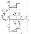
- Figure 1 shows schematically a section of an exhaust pipe 2 of a truck diesel engine, not shown.
- a temperature sensor 4 a hydrolysis catalytic converter 6, a DeNO x catalytic converter 8, an oxidation catalytic converter 10 and a further temperature sensor 12 are installed in series in the exhaust gas line 2.
- a reducing agent supply line 14 is connected to the hydrolysis catalytic converter 6 and, starting from a storage container 16 for a reducing agent 18, opens into the hydrolysis catalytic converter 6 via an injection valve 20.
- the reducing agent 18 is a substance which can be converted into ammonia, for example an aqueous urea solution, that can be carried safely in the vehicle.
- the DeNO x catalyst 8 comprises two partial catalysts 22, 24, which differ in their structure.
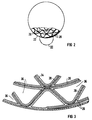
- the partial catalytic converter 22 consists of sheet metal 26 arranged in a spiral shape and made of a stainless steel or a thermistor alloy. Between the individual layers of the sheet 26, a corrugated sheet 28 is inserted, which supports the entire spiral structure of the sheet 26.
- the sheet 28 is also made of a stainless steel or a thermistor alloy and, like the sheet 26, has a thickness of approximately 40 ⁇ m.
- the catalytically active layer 34 (see FIG. 3) applied both to the sheet 26 and to the wave-shaped sheet 28 has in the exemplary embodiment a thickness of approximately 40 ⁇ m and a specific surface area of approximately 50 m 2 / g, which is a primary particle size in the starting material of approximately 15 nm.
- the part 22 has a length l1 of about 30 cm in the embodiment.
- a catalytically active substance in the catalytically active layer 34 titanium oxide (TiO2) with one or more of the additives molybdenum oxide (MoO3), tungsten oxide (WO) and vanadium oxide (V2O5) is used. It is also conceivable to use a phase of the empirical formula V x Mo y O 32-z with x, y ⁇ 1, x + y ⁇ 12, z ⁇ 1 as a particularly catalytically active substance in the catalytically active layer 34.
- the flow through the catalyst part 22 is essentially laminar.
- deflection elements for the exhaust gas 30 can be provided on the sheets 26 and 28, as a result of which the interaction of the reducing agent and the nitrogen oxides in the exhaust gas 30 with the catalytically active layer 34 is increased.
- the course of the thickness d of the catalytically active layer 34 is shown in a step-like manner in the diagram above the catalytic converter 8.
- the thickness d of the catalytically active layer 34 could, however, likewise run along the dotted or the dash-dotted line. This with regard to the thickness d can also be transferred to the course of the specific surface 0 along the catalyst 8.
- the step-like course is realized in the diagram below the catalytic converter.
- Figure 3 shows an enlarged view of the detail dashed in Figure 2.
- the catalytically active layer 34 which is applied, for example, by dipping or rolling onto the sheets 26, 28, is also shown for clarification.
- the exhaust gas 30 flows through the gas spaces 36 which are left free between the sheets 26, 28.
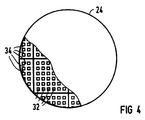
- FIG. 4 shows the section along the line IV-IV in FIG. 1 through the partial catalytic converter 24 of the DeNO x catalytic converter 8.
- this partial catalytic converter 24 arranged behind the part 22 in the flow direction of the exhaust gas 30 is designed as an all-ceramic honeycomb.
- the walls of the honeycomb body are both a catalyst support and a catalytically active layer.
- the wall thickness of the honeycomb is approximately 300 ⁇ m, which corresponds to a multiple of the thickness of the reaction zone.
- the thickness of the reaction zone is defined as the depth in the catalytically active layer at which the nitrogen oxide content has dropped to almost zero.
- the thickness of the reaction zone depends, among other things, on the NO x concentration and the pore radii and is generally between 5 and 200 ⁇ m; in the exemplary embodiment it is approximately 40 ⁇ m.
- the specific surface area of the honeycomb material (catalytically active material) is approximately 100 m 2 / g, which corresponds to a primary particle size of the starting material of approximately 30 nm.
- the catalytically active layer 34 consists of the same materials already mentioned above for the partial catalyst 22.
- the specific surfaces of the catalytically active layer 34 are thus set within the preferred range from 20 to 100 m 2 / g at the exhaust gas inlet into the partial catalytic converter 22 and within the preferred range from 40 to 600 m 2 / g at the exhaust gas outlet. Large specific surfaces of the catalytically active layer 34 can also be generated, for example, by an additional coating of the catalyst parts 22, 24 with zeolites and / or with aluminum oxide.
- the exhaust gas 30 mixed with ammonia then flows into the DeNO x catalytic converter 8 and in this first into the catalytic converter part 22.
- this catalytic converter part can only store relatively little ammonia, but has a quick light-off behavior and can also be filled with ammonia relatively quickly after it has been emptied.
- the majority of the nitrogen oxides contained in the exhaust gas are already converted in this part 22 with the ammonia by contacting the catalytically active layer 34 to nitrogen and water.
- the nitrogen oxides which have not yet been catalytically converted in the catalyst part 22 then become when flowing through the catalyst part 24 implemented.
- Ammonia discharged from the catalytic converter part 24 with the exhaust gas 30 is catalytically converted by means of the oxidation catalytic converter 10 together with hydrocarbons and carbon monoxide still contained in the exhaust gas, so that a largely pollutant-free exhaust gas 30 is fed to a silencer (not shown further here).
- the nitrogen oxide concentration can increase to approximately 1300 ppm, the air mass flow to approximately 1600 g / h and the exhaust gas temperature to approximately 540 ° C.
- This increases the reaction of nitrogen oxides and ammonia on the one hand and leads to a reduction in the amount of ammonia stored in the DeNO x catalyst 8.
- ammonia is released, corresponding to the temperature rise of the exhaust gas 30, which causes a decreasing storage capacity of the catalytically active layer 34 for ammonia.
- the catalytic converter part 24 has a greater layer thickness of the catalytically active layer 34 and twice the specific surface area per unit length compared to the catalytic converter part 22 at a length l2 of approximately 15 cm selected in the exemplary embodiment, this catalytic converter part 24 serves as a catchment store for that due to the temperature rise of the exhaust gas 30 desorbed ammonia. Without these properties of the DeNO x catalytic converter 8 according to the invention, large amounts of ammonia would be desorbed in the event of positive load jumps, so that the downstream oxidation catalytic converter 10 would also not be able to prevent a considerable ammonia slip and thus a considerable odor nuisance and air pollution.
- the arrangement according to the invention of a plate catalytic converter as the first partial catalytic converter 22 in front of a honeycomb catalytic converter as the second partial catalytic converter 24 also weakens the thermal load on the all-ceramic honeycomb caused by temperature jumps. Because the sheets 26, 28 smooth in the partial catalytic converter 22 due to their heat conduction and heat radiation characteristics too large temperature changes. Nevertheless, it would be equally conceivable to replace the catalytic converter part 22 with all-ceramic honeycomb catalysts, the wall thickness of which increases in the flow direction of the exhaust gas 30 or the number of cells per surface area increases in the flow direction of the exhaust gas 30.
- the specific storage capacity of the catalytically active layer 34 in the exemplary embodiment for a temperature of 250 ° C. about 3 g ammonia per kg catalyst and at 500 ° C. about 0.5 g ammonia per kg Catalyst lies.
- all substances that are relatively easy to convert into ammonia are conceivable as reducing agents 18.
- hydrocarbons, carbon monoxide, etc. are also conceivable.
- a ceramic support for example made of aluminum oxide Al2O3 or similar minerals, could also be provided as a support for the catalytically active layer 34.
Landscapes
- Engineering & Computer Science (AREA)
- Chemical & Material Sciences (AREA)
- Chemical Kinetics & Catalysis (AREA)
- Combustion & Propulsion (AREA)
- Health & Medical Sciences (AREA)
- Mechanical Engineering (AREA)
- General Engineering & Computer Science (AREA)
- Toxicology (AREA)
- Biomedical Technology (AREA)
- Environmental & Geological Engineering (AREA)
- Analytical Chemistry (AREA)
- General Chemical & Material Sciences (AREA)
- Oil, Petroleum & Natural Gas (AREA)
- Ceramic Engineering (AREA)
- Exhaust Gas Treatment By Means Of Catalyst (AREA)
- Exhaust Gas After Treatment (AREA)
- Catalysts (AREA)
Applications Claiming Priority (2)
| Application Number | Priority Date | Filing Date | Title |
|---|---|---|---|
| DE4309891 | 1993-03-26 | ||
| DE4309891 | 1993-03-26 |
Publications (2)
| Publication Number | Publication Date |
|---|---|
| EP0617199A1 true EP0617199A1 (fr) | 1994-09-28 |
| EP0617199B1 EP0617199B1 (fr) | 1996-01-31 |
Family
ID=6483953
Family Applications (1)
| Application Number | Title | Priority Date | Filing Date |
|---|---|---|---|
| EP94103916A Expired - Lifetime EP0617199B1 (fr) | 1993-03-26 | 1994-03-14 | Catalyseur pour le réduction de la teneur en oxydes d'azote dans le gaz d'échappement d'un moteur à combustion interne |
Country Status (7)
| Country | Link |
|---|---|
| US (1) | US5833932A (fr) |
| EP (1) | EP0617199B1 (fr) |
| JP (1) | JPH06343877A (fr) |
| AT (1) | ATE133752T1 (fr) |
| DE (1) | DE59400100D1 (fr) |
| DK (1) | DK0617199T3 (fr) |
| ES (1) | ES2083301T3 (fr) |
Cited By (12)
| Publication number | Priority date | Publication date | Assignee | Title |
|---|---|---|---|---|
| WO1998051402A1 (fr) * | 1997-05-14 | 1998-11-19 | Hjs Fahrzeugtechnik Gmbh & Co. | Procede et dispositif pour la reduction des oxydes nitriques sur un pot catalytique a reduction selective catalytique |
| DE19816323C1 (de) * | 1998-04-11 | 1999-10-14 | Dornier Gmbh | Verfahren zur katalytischen Reduktion von Stickoxiden unter Zugabe von Reduktionsmitteln in motorischen Abgasen |
| EP1074291A1 (fr) * | 1999-08-04 | 2001-02-07 | Technologies Avancees & Membranes Industrielles S.A. | Membrane pour filtration tangentielle et son procédé de fabrication |
| US6312650B1 (en) * | 1996-05-15 | 2001-11-06 | Silentor Holding A/S | Silencer |
| EP1106799A4 (fr) * | 1998-06-23 | 2003-02-05 | Toyota Motor Co Ltd | Dispositif de reglage d'emission de gaz d'echappement dans un moteur a combustion interne |
| FR2890108A1 (fr) * | 2005-08-29 | 2007-03-02 | Peugeot Citroen Automobiles Sa | Ligne d'echappement et de purification des gaz d'echappement d'un moteur de vehicule automobile et vehicule comportant une telle ligne |
| WO2007039240A1 (fr) * | 2005-10-06 | 2007-04-12 | Emitec Gesellschaft Für Emissionstechnologie Mbh | Procede et dispositif de reduction de la fraction d'oxyde d'azote dans les gaz d'echappement d'un moteur a combustion interne |
| DE102010053751A1 (de) * | 2010-10-28 | 2012-05-03 | Oerlikon Trading Ag, Trübbach | Molybdänmonoxidschichten und deren Herstellung mittels PVD |
| CN102027207B (zh) * | 2008-03-17 | 2013-07-17 | 康明斯过滤Ip公司 | 废气清洁系统、设备和方法 |
| WO2014128270A1 (fr) * | 2013-02-25 | 2014-08-28 | Umicore Ag & Co. Kg | Catalyseur scr avec rendement en nox amélioré |
| US9797286B2 (en) | 2013-10-30 | 2017-10-24 | GM Global Technology Operations LLC | SCR filter washcoat thickness efficiency compensation system |
| DE102014115630B4 (de) | 2013-10-30 | 2022-09-29 | GM Global Technology Operations, LLC (n.d. Ges. d. Staates Delaware) | Abgasbehandlungssystem, Steuermodul und Verfahren zum Steuern eines Abgasbehandlungssystems |
Families Citing this family (41)
| Publication number | Priority date | Publication date | Assignee | Title |
|---|---|---|---|---|
| DE3904493A1 (de) * | 1989-02-15 | 1990-08-16 | Deere & Co | Antriebsvorrichtung fuer mindestens zwei radpaare |
| US5943858A (en) * | 1995-05-19 | 1999-08-31 | Siemens Aktiengesellschaft | Premixing chamber for an exhaust gas purification system |
| DE19531028A1 (de) * | 1995-08-23 | 1997-02-27 | Siemens Ag | Verfahren zur Abgasreinigung und Abgas-Reinigungseinrichtung für einen Verbrennungsmotor |
| DE19816482C2 (de) * | 1998-04-14 | 2001-11-29 | Siemens Ag | Plattenkatalysator |
| ATE306608T1 (de) * | 1998-11-13 | 2005-10-15 | Engelhard Corp | Katalysator und verfahren zur reduzierung der abgasemissionen |
| DE19919472C2 (de) * | 1999-04-29 | 2001-04-19 | Bosch Gmbh Robert | Vorrichtung und Verfahren zur Detektion von Ammoniak |
| US6266955B1 (en) | 1999-08-20 | 2001-07-31 | Caterpillar Inc. | Diagnostic system for an emissions control on an engine |
| US6314722B1 (en) | 1999-10-06 | 2001-11-13 | Matros Technologies, Inc. | Method and apparatus for emission control |
| US6311484B1 (en) | 2000-02-22 | 2001-11-06 | Engelhard Corporation | System for reducing NOx transient emission |
| US6919047B1 (en) * | 2000-10-10 | 2005-07-19 | Corning Incorporated | Reduction of nitrogen oxides in diesel exhaust gases and fuel injection system |
| US6415602B1 (en) | 2000-10-16 | 2002-07-09 | Engelhard Corporation | Control system for mobile NOx SCR applications |
| US6449947B1 (en) * | 2001-10-17 | 2002-09-17 | Fleetguard, Inc. | Low pressure injection and turbulent mixing in selective catalytic reduction system |
| US6601385B2 (en) * | 2001-10-17 | 2003-08-05 | Fleetguard, Inc. | Impactor for selective catalytic reduction system |
| JP3951774B2 (ja) * | 2002-03-29 | 2007-08-01 | 三菱ふそうトラック・バス株式会社 | 内燃機関のNОx浄化装置 |
| US7093427B2 (en) * | 2002-11-21 | 2006-08-22 | Ford Global Technologies, Llc | Exhaust gas aftertreatment systems |
| JP4152833B2 (ja) * | 2003-07-30 | 2008-09-17 | 日産ディーゼル工業株式会社 | エンジンの排気浄化装置 |
| US7117669B2 (en) * | 2004-05-05 | 2006-10-10 | Eaton Corporation | Temperature swing adsorption and selective catalytic reduction NOx removal system |
| US6996975B2 (en) * | 2004-06-25 | 2006-02-14 | Eaton Corporation | Multistage reductant injection strategy for slipless, high efficiency selective catalytic reduction |
| US7213395B2 (en) * | 2004-07-14 | 2007-05-08 | Eaton Corporation | Hybrid catalyst system for exhaust emissions reduction |
| US7178328B2 (en) * | 2004-12-20 | 2007-02-20 | General Motors Corporation | System for controlling the urea supply to SCR catalysts |
| DE102005017402A1 (de) * | 2005-04-15 | 2006-10-19 | Emitec Gesellschaft Für Emissionstechnologie Mbh | Verfahren und Vorrichtung zur dosierten Bereitstellung eines, insbesondere als Feststoff vorliegenden, Reduktionsmittels für Abgassysteme |
| JP4432917B2 (ja) | 2006-03-06 | 2010-03-17 | トヨタ自動車株式会社 | 内燃機関の排気浄化装置 |
| US20080202097A1 (en) * | 2007-02-28 | 2008-08-28 | Caterpillar Inc. | Engine exhaust treatment system |
| US8209956B2 (en) * | 2007-07-31 | 2012-07-03 | Caterpillar Inc. | SCR emissions control system |
| US8001769B2 (en) * | 2007-08-20 | 2011-08-23 | Caterpillar Inc. | Control of SCR system having a filtering device |
| US7992380B2 (en) * | 2007-08-23 | 2011-08-09 | Caterpillar Inc. | Emission control system implementing reduction agent injection |
| US8713917B2 (en) * | 2007-08-30 | 2014-05-06 | GM Global Technology Operations LLC | Method for reducing NH3 release from SCR catalysts during thermal transients |
| US7613561B1 (en) * | 2008-04-24 | 2009-11-03 | Honeywell International Inc | Measurement of NO and NO2 for control of selective catalytic reduction |
| WO2010014217A1 (fr) * | 2008-07-29 | 2010-02-04 | Rafael Espinoza | Réacteur à panneau de type coussin et procédé correspondant |
| WO2010131369A1 (fr) * | 2009-05-15 | 2010-11-18 | トヨタ自動車株式会社 | Catalyseur de purification de gaz d'échappement et son procédé de fabrication |
| DE112010003455T5 (de) * | 2009-08-28 | 2012-07-26 | Honda Motor Co., Ltd. | Abgasreinigungsvorrichtung für elnen Verbrennungsmotor |
| US20110064633A1 (en) * | 2009-09-14 | 2011-03-17 | Ford Global Technologies, Llc | Multi-Functional Catalyst Block and Method of Using the Same |
| MX2015011264A (es) | 2013-03-14 | 2016-04-28 | Basf Corp | Sistema de catalizadores para reduccion catalitica selectiva. |
| US9468915B2 (en) | 2013-03-14 | 2016-10-18 | Basf Corporation | Selective catalytic reduction catalyst system |
| US10626772B2 (en) | 2014-07-18 | 2020-04-21 | Cummins Inc. | SCR exhaust aftertreatment apparatus, system and methods including multiple washcoat formulations |
| WO2016011366A1 (fr) * | 2014-07-18 | 2016-01-21 | Cummins Inc. | Appareils, systèmes et procédés de post-traitement de gaz d'échappement de rcs comprenant de multiples formulations d'enduit |
| JP7171164B2 (ja) * | 2017-04-14 | 2022-11-15 | 三菱重工業株式会社 | 燃焼排ガス処理方法、燃焼排ガス処理装置およびそれのメンテナンス方法 |
| WO2020043662A1 (fr) * | 2018-08-28 | 2020-03-05 | Umicore Ag & Co. Kg | Catalyseur destiné à être utilisé dans la réduction catalytique sélective d'oxydes d'azote |
| EP3730210A1 (fr) * | 2019-04-26 | 2020-10-28 | Umicore Ag & Co. Kg | Filtre en céramique catalyseur pour bougie d'élimination de particules combinée et de réduction catalytique sélective (scr) d'oxydes d'azote |
| CN109763883B (zh) * | 2019-02-11 | 2021-03-12 | 无锡威孚力达催化净化器有限责任公司 | 一种scr系统氨气泄露的检测方法、装置及系统 |
| MX2024003192A (es) * | 2023-03-17 | 2024-09-18 | Polaris Inc | Sistema de aire/escape para un vehiculo. |
Citations (6)
| Publication number | Priority date | Publication date | Assignee | Title |
|---|---|---|---|---|
| FR2393145A1 (fr) * | 1977-05-31 | 1978-12-29 | Caterpillar Tractor Co | Procede et dispositif catalytiques d'epuration des gaz d'echappement |
| JPS6118438A (ja) * | 1984-07-04 | 1986-01-27 | Toyota Motor Corp | モノリス触媒の製造方法 |
| JPS6318123A (ja) * | 1986-07-10 | 1988-01-26 | Fuji Heavy Ind Ltd | 触媒コンバ−タ |
| EP0364694A1 (fr) * | 1988-09-03 | 1990-04-25 | Bayer Ag | Procédé de réduction d'oxydes d'azote contenue dans des gaz d'échappement avec un catalyseur contenant du zéolithe |
| JPH03258326A (ja) * | 1990-03-07 | 1991-11-18 | Babcock Hitachi Kk | 排ガス脱硝装置および排ガス脱硝方法 |
| EP0470334A1 (fr) * | 1990-08-08 | 1992-02-12 | Siemens Aktiengesellschaft | Catalysateur d'oxydes mixtes résistant à l'arsénic et son procédé de préparation |
Family Cites Families (16)
| Publication number | Priority date | Publication date | Assignee | Title |
|---|---|---|---|---|
| US3768982A (en) * | 1971-06-22 | 1973-10-30 | Ford Motor Co | Catalytic converter with electrically preheated catalyst |
| IT1070099B (it) * | 1975-09-23 | 1985-03-25 | Degussa | Catalizzatore supportato monolitico e disposizione di catalizzatori supportati monolitici per la depurazione dei gas di scarico di motori a combustione |
| JPS5413815A (en) * | 1977-07-02 | 1979-02-01 | Nippon Soken Inc | Caralytic converter for exhaust gas |
| US4390355A (en) * | 1982-02-02 | 1983-06-28 | General Motors Corporation | Wall-flow monolith filter |
| DE8438260U1 (de) * | 1984-12-29 | 1985-04-11 | Süddeutsche Kühlerfabrik Julius Fr. Behr GmbH & Co KG, 7000 Stuttgart | Traegermatrix, insbesondere fuer einen katalytischen reaktor zur abgasreinigung |
| DE3531809A1 (de) * | 1985-09-06 | 1987-03-26 | Kraftwerk Union Ag | Katalysatormaterial zur reduktion von stickoxiden |
| DE3531810A1 (de) * | 1985-09-06 | 1987-03-19 | Kraftwerk Union Ag | Katalysatormaterial zur reduktion von stickoxiden |
| DE3536315A1 (de) * | 1985-10-11 | 1987-04-16 | Sueddeutsche Kuehler Behr | Katalysatoranordnung zur reinigung von abgasen, insbesondere einer brennkraftmaschine |
| DE3813312A1 (de) * | 1988-04-20 | 1989-11-02 | Siemens Ag | Plattenfoermiger katalysator zur verminderung der stickoxide in rauchgasen und verfahren zu seiner herstellung |
| DE3826137A1 (de) * | 1988-08-01 | 1990-02-08 | Siemens Ag | Denox-platten-katalysator und verfahren zu seiner herstellung |
| JPH04118053A (ja) * | 1989-12-29 | 1992-04-20 | Tokyo Roki Kk | エンジンの排気ガス浄化用触媒 |
| US5229080A (en) * | 1990-06-29 | 1993-07-20 | Ngk Insulators, Ltd. | Resistance adjusting type heater and catalytic converter |
| DE4024942A1 (de) * | 1990-08-06 | 1992-02-13 | Emitec Emissionstechnologie | Monolithischer metallischer wabenkoerper mit variierender kanalzahl |
| US5270277A (en) * | 1990-08-08 | 1993-12-14 | Siemens Aktiengesellschaft | Arsenic-resistant catalyst and method for producing the same |
| DE4025587A1 (de) * | 1990-08-11 | 1992-02-13 | Basf Ag | Verfahren zur herstellung von katalysatoren |
| DE4032085A1 (de) * | 1990-10-10 | 1992-04-16 | Didier Werke Ag | Katalysatoranordnung zur reduktion von stickoxiden |
-
1994
- 1994-03-14 EP EP94103916A patent/EP0617199B1/fr not_active Expired - Lifetime
- 1994-03-14 DE DE59400100T patent/DE59400100D1/de not_active Expired - Fee Related
- 1994-03-14 ES ES94103916T patent/ES2083301T3/es not_active Expired - Lifetime
- 1994-03-14 AT AT94103916T patent/ATE133752T1/de not_active IP Right Cessation
- 1994-03-14 DK DK94103916.6T patent/DK0617199T3/da active
- 1994-03-24 JP JP6077987A patent/JPH06343877A/ja active Pending
-
1997
- 1997-10-20 US US08/953,964 patent/US5833932A/en not_active Expired - Fee Related
Patent Citations (6)
| Publication number | Priority date | Publication date | Assignee | Title |
|---|---|---|---|---|
| FR2393145A1 (fr) * | 1977-05-31 | 1978-12-29 | Caterpillar Tractor Co | Procede et dispositif catalytiques d'epuration des gaz d'echappement |
| JPS6118438A (ja) * | 1984-07-04 | 1986-01-27 | Toyota Motor Corp | モノリス触媒の製造方法 |
| JPS6318123A (ja) * | 1986-07-10 | 1988-01-26 | Fuji Heavy Ind Ltd | 触媒コンバ−タ |
| EP0364694A1 (fr) * | 1988-09-03 | 1990-04-25 | Bayer Ag | Procédé de réduction d'oxydes d'azote contenue dans des gaz d'échappement avec un catalyseur contenant du zéolithe |
| JPH03258326A (ja) * | 1990-03-07 | 1991-11-18 | Babcock Hitachi Kk | 排ガス脱硝装置および排ガス脱硝方法 |
| EP0470334A1 (fr) * | 1990-08-08 | 1992-02-12 | Siemens Aktiengesellschaft | Catalysateur d'oxydes mixtes résistant à l'arsénic et son procédé de préparation |
Non-Patent Citations (3)
| Title |
|---|
| DATABASE WPI Section Ch Week 9201, 1992 Derwent World Patents Index; Class E11, AN 92-004258 * |
| PATENT ABSTRACTS OF JAPAN vol. 012, no. 222 (M - 712) 24 June 1988 (1988-06-24) * |
| PATENT ABSTRACTS OF JAPAN vol. 10, no. 166 (C - 353) 13 June 1986 (1986-06-13) * |
Cited By (24)
| Publication number | Priority date | Publication date | Assignee | Title |
|---|---|---|---|---|
| US6312650B1 (en) * | 1996-05-15 | 2001-11-06 | Silentor Holding A/S | Silencer |
| WO1998051402A1 (fr) * | 1997-05-14 | 1998-11-19 | Hjs Fahrzeugtechnik Gmbh & Co. | Procede et dispositif pour la reduction des oxydes nitriques sur un pot catalytique a reduction selective catalytique |
| US6399034B1 (en) | 1997-05-14 | 2002-06-04 | Hjs Fahrzeugtechnik Gmbh & Co. | Process for reducing nitrogen oxides on SCR catalyst |
| DE19816323C1 (de) * | 1998-04-11 | 1999-10-14 | Dornier Gmbh | Verfahren zur katalytischen Reduktion von Stickoxiden unter Zugabe von Reduktionsmitteln in motorischen Abgasen |
| US7086223B2 (en) | 1998-06-23 | 2006-08-08 | Toyota Jidosha Kabushiki Kaisha | Exhaust gas purification device of internal combustion engine |
| EP1106799A4 (fr) * | 1998-06-23 | 2003-02-05 | Toyota Motor Co Ltd | Dispositif de reglage d'emission de gaz d'echappement dans un moteur a combustion interne |
| US6959540B2 (en) | 1998-06-23 | 2005-11-01 | Toyota Jidosha Kabushiki Kaisha | Exhaust gas purification device of internal combustion engine |
| US7086222B2 (en) | 1998-06-23 | 2006-08-08 | Toyota Jidosha Kabushiki Kaisha | Exhaust gas purification device of internal combustion engine |
| US7272924B2 (en) | 1998-06-23 | 2007-09-25 | Toyota Jidosha Kabushiki Kaisha | Exhaust gas purification device of internal combustion engine |
| FR2797198A1 (fr) * | 1999-08-04 | 2001-02-09 | Tami Ind | Membrane pour filtration tangentielle et son procede de fabrication |
| EP1074291A1 (fr) * | 1999-08-04 | 2001-02-07 | Technologies Avancees & Membranes Industrielles S.A. | Membrane pour filtration tangentielle et son procédé de fabrication |
| FR2890108A1 (fr) * | 2005-08-29 | 2007-03-02 | Peugeot Citroen Automobiles Sa | Ligne d'echappement et de purification des gaz d'echappement d'un moteur de vehicule automobile et vehicule comportant une telle ligne |
| EP1760281A1 (fr) * | 2005-08-29 | 2007-03-07 | Peugeot Citroën Automobiles S.A. | Ligne d'échappement et de purification des gaz d'échappement d'un moteur de véhicule automobile et véhicule comportant une telle ligne |
| WO2007039240A1 (fr) * | 2005-10-06 | 2007-04-12 | Emitec Gesellschaft Für Emissionstechnologie Mbh | Procede et dispositif de reduction de la fraction d'oxyde d'azote dans les gaz d'echappement d'un moteur a combustion interne |
| US7765798B2 (en) | 2005-10-06 | 2010-08-03 | Emitec Gesellschaft Fuer Emissionstechnologie Mbh | Method and device for reducing the nitrogen oxide proportion in the exhaust gas of an internal combustion engine |
| CN102027207B (zh) * | 2008-03-17 | 2013-07-17 | 康明斯过滤Ip公司 | 废气清洁系统、设备和方法 |
| DE102010053751A1 (de) * | 2010-10-28 | 2012-05-03 | Oerlikon Trading Ag, Trübbach | Molybdänmonoxidschichten und deren Herstellung mittels PVD |
| WO2014128270A1 (fr) * | 2013-02-25 | 2014-08-28 | Umicore Ag & Co. Kg | Catalyseur scr avec rendement en nox amélioré |
| DE102013003112A1 (de) * | 2013-02-25 | 2014-08-28 | Umicore Ag & Co. Kg | SCR-Katalysator mit verbessertem NOx-Umsatz |
| DE102013003112B4 (de) * | 2013-02-25 | 2017-06-14 | Umicore Ag & Co. Kg | SCR-Katalysator mit verbessertem NOx-Umsatz |
| US9694320B2 (en) | 2013-02-25 | 2017-07-04 | Umicore Ag & Co. Kg | SCR catalytic converter having improved NOx conversion |
| US9797286B2 (en) | 2013-10-30 | 2017-10-24 | GM Global Technology Operations LLC | SCR filter washcoat thickness efficiency compensation system |
| DE102014115630B4 (de) | 2013-10-30 | 2022-09-29 | GM Global Technology Operations, LLC (n.d. Ges. d. Staates Delaware) | Abgasbehandlungssystem, Steuermodul und Verfahren zum Steuern eines Abgasbehandlungssystems |
| DE102014115631B4 (de) | 2013-10-30 | 2022-09-29 | GM Global Technology Operations, LLC (n.d. Ges. d. Staates Delaware) | Abgasbehandlungssystem, Steuermodul und Verfahren zum dynamischen Erzeugen eines Reduktionsmittelspeichermodells |
Also Published As
| Publication number | Publication date |
|---|---|
| DK0617199T3 (da) | 1996-07-01 |
| ATE133752T1 (de) | 1996-02-15 |
| EP0617199B1 (fr) | 1996-01-31 |
| ES2083301T3 (es) | 1996-04-01 |
| JPH06343877A (ja) | 1994-12-20 |
| US5833932A (en) | 1998-11-10 |
| DE59400100D1 (de) | 1996-03-14 |
Similar Documents
| Publication | Publication Date | Title |
|---|---|---|
| EP0617199B1 (fr) | Catalyseur pour le réduction de la teneur en oxydes d'azote dans le gaz d'échappement d'un moteur à combustion interne | |
| DE69217108T2 (de) | Katalytisches Reaktorsystem | |
| DE3877229T2 (de) | Verfahren zum entfernen von nox aus fluidstroemen. | |
| DE60035734T3 (de) | Abgasreiningungssystem für einen Dieselmotor | |
| EP0879633B1 (fr) | Procédé pour purifier un gaz d'échappement maigre et système catalytique correspondant | |
| DE69124528T2 (de) | Katalysatorstruktur mit integriertem wärmeaustausch | |
| DE60109300T2 (de) | Verfahren und vorrichtung zur entfernung von stickoxiden im abgas einer brennkraftmaschine | |
| DE102011110164B4 (de) | Abgasnachbehandlungssystem mit bifunktionellen Katalysatormaterialien und Verfahren zur Magerabgas-NOx-Reduktion | |
| EP1625285B1 (fr) | Procede et dispositif d'epuration de gaz d'echappement | |
| EP3003537B1 (fr) | Méthode de réduction des composants nocifs dans les gaz d'échappement des moteurs à essence. | |
| EP2825294B1 (fr) | Élément catalytique d'un système de purification des gaz d'échappement d'un véhicule motorisé et utilisation d'un élément catalytique | |
| EP1153648A1 (fr) | Catalyseur structuré pour la réduction sélective d'oxydes d'azote par l'ammoniac utilisant un composé hydrolisable | |
| EP3724469A1 (fr) | Combinaison d'une rcs à base de zéolite avec une rcs à base de manganèse dans la dérivation | |
| EP0611594A1 (fr) | Catalyseur pour la conversion de réactants dans un mélange gazeux | |
| DE4221363A1 (de) | Verfahren und vorrichtung zum reinigen eines abgases | |
| EP1985819A2 (fr) | Système de traitement de gaz d'échappement | |
| EP0779095A1 (fr) | Procédé et dispositif pour la purification catalytique de gaz | |
| EP1078150A1 (fr) | Pot catalytique, notamment pour moteur diesel ou moteur a melange pauvre | |
| DE102011012799A1 (de) | Katalysator zur Entfernung von Stickoxiden aus dem Abgas von Dieselmotoren | |
| WO1998039083A1 (fr) | Systeme catalyseur pour l'epuration des gaz d'echappement de moteurs diesel | |
| EP1558842B1 (fr) | Systeme d'echappement de gaz et procede pour le faire fonctionner | |
| EP2644859B1 (fr) | Procédé destiné à l'utilisation en liaison avec un dispositif de post-traitement de gaz d'échappement | |
| EP2166203B1 (fr) | Dispositif de nettoyage d'un flux de gaz d'échappement d'un moteur à combustion interne d'un véhicule automobile, notamment un véhicule utilitaire | |
| DD296617A5 (de) | Katalysator zur reinigung von abgasen aus ueberstaechiometrisch betriebenen verbrennungsmotoren und gasturbinen | |
| WO2006097131A1 (fr) | Corps a nids d'abeilles pourvu de moyens d'introduction de reactif, procede correspondant et systeme associe |
Legal Events
| Date | Code | Title | Description |
|---|---|---|---|
| PUAI | Public reference made under article 153(3) epc to a published international application that has entered the european phase |
Free format text: ORIGINAL CODE: 0009012 |
|
| AK | Designated contracting states |
Kind code of ref document: A1 Designated state(s): AT BE CH DE DK ES FR GB IT LI NL SE |
|
| 17P | Request for examination filed |
Effective date: 19941018 |
|
| 17Q | First examination report despatched |
Effective date: 19950301 |
|
| GRAA | (expected) grant |
Free format text: ORIGINAL CODE: 0009210 |
|
| AK | Designated contracting states |
Kind code of ref document: B1 Designated state(s): AT BE CH DE DK ES FR GB IT LI NL SE |
|
| REF | Corresponds to: |
Ref document number: 133752 Country of ref document: AT Date of ref document: 19960215 Kind code of ref document: T |
|
| REF | Corresponds to: |
Ref document number: 59400100 Country of ref document: DE Date of ref document: 19960314 |
|
| REG | Reference to a national code |
Ref country code: CH Ref legal event code: NV Representative=s name: SIEMENS-ALBIS AKTIENGESELLSCHAFT |
|
| REG | Reference to a national code |
Ref country code: ES Ref legal event code: FG2A Ref document number: 2083301 Country of ref document: ES Kind code of ref document: T3 |
|
| GBT | Gb: translation of ep patent filed (gb section 77(6)(a)/1977) |
Effective date: 19960313 |
|
| ITF | It: translation for a ep patent filed | ||
| ET | Fr: translation filed | ||
| REG | Reference to a national code |
Ref country code: DK Ref legal event code: T3 |
|
| PLBE | No opposition filed within time limit |
Free format text: ORIGINAL CODE: 0009261 |
|
| STAA | Information on the status of an ep patent application or granted ep patent |
Free format text: STATUS: NO OPPOSITION FILED WITHIN TIME LIMIT |
|
| 26N | No opposition filed | ||
| REG | Reference to a national code |
Ref country code: GB Ref legal event code: IF02 |
|
| PGFP | Annual fee paid to national office [announced via postgrant information from national office to epo] |
Ref country code: NL Payment date: 20030317 Year of fee payment: 10 |
|
| PGFP | Annual fee paid to national office [announced via postgrant information from national office to epo] |
Ref country code: DK Payment date: 20030324 Year of fee payment: 10 Ref country code: CH Payment date: 20030324 Year of fee payment: 10 |
|
| PGFP | Annual fee paid to national office [announced via postgrant information from national office to epo] |
Ref country code: ES Payment date: 20030325 Year of fee payment: 10 |
|
| PGFP | Annual fee paid to national office [announced via postgrant information from national office to epo] |
Ref country code: BE Payment date: 20030326 Year of fee payment: 10 |
|
| PGFP | Annual fee paid to national office [announced via postgrant information from national office to epo] |
Ref country code: GB Payment date: 20040225 Year of fee payment: 11 |
|
| PG25 | Lapsed in a contracting state [announced via postgrant information from national office to epo] |
Ref country code: ES Free format text: LAPSE BECAUSE OF NON-PAYMENT OF DUE FEES Effective date: 20040315 |
|
| PGFP | Annual fee paid to national office [announced via postgrant information from national office to epo] |
Ref country code: FR Payment date: 20040318 Year of fee payment: 11 |
|
| PGFP | Annual fee paid to national office [announced via postgrant information from national office to epo] |
Ref country code: AT Payment date: 20040322 Year of fee payment: 11 |
|
| PGFP | Annual fee paid to national office [announced via postgrant information from national office to epo] |
Ref country code: SE Payment date: 20040323 Year of fee payment: 11 |
|
| PG25 | Lapsed in a contracting state [announced via postgrant information from national office to epo] |
Ref country code: LI Free format text: LAPSE BECAUSE OF NON-PAYMENT OF DUE FEES Effective date: 20040331 Ref country code: DK Free format text: LAPSE BECAUSE OF NON-PAYMENT OF DUE FEES Effective date: 20040331 Ref country code: CH Free format text: LAPSE BECAUSE OF NON-PAYMENT OF DUE FEES Effective date: 20040331 Ref country code: BE Free format text: LAPSE BECAUSE OF NON-PAYMENT OF DUE FEES Effective date: 20040331 |
|
| PGFP | Annual fee paid to national office [announced via postgrant information from national office to epo] |
Ref country code: DE Payment date: 20040920 Year of fee payment: 11 |
|
| BERE | Be: lapsed |
Owner name: *SIEMENS A.G. Effective date: 20040331 |
|
| REG | Reference to a national code |
Ref country code: CH Ref legal event code: PL |
|
| PG25 | Lapsed in a contracting state [announced via postgrant information from national office to epo] |
Ref country code: IT Free format text: LAPSE BECAUSE OF NON-PAYMENT OF DUE FEES;WARNING: LAPSES OF ITALIAN PATENTS WITH EFFECTIVE DATE BEFORE 2007 MAY HAVE OCCURRED AT ANY TIME BEFORE 2007. THE CORRECT EFFECTIVE DATE MAY BE DIFFERENT FROM THE ONE RECORDED. Effective date: 20050314 Ref country code: GB Free format text: LAPSE BECAUSE OF NON-PAYMENT OF DUE FEES Effective date: 20050314 Ref country code: AT Free format text: LAPSE BECAUSE OF NON-PAYMENT OF DUE FEES Effective date: 20050314 |
|
| PG25 | Lapsed in a contracting state [announced via postgrant information from national office to epo] |
Ref country code: SE Free format text: LAPSE BECAUSE OF NON-PAYMENT OF DUE FEES Effective date: 20050315 |
|
| REG | Reference to a national code |
Ref country code: ES Ref legal event code: FD2A Effective date: 20040315 |
|
| PG25 | Lapsed in a contracting state [announced via postgrant information from national office to epo] |
Ref country code: NL Free format text: LAPSE BECAUSE OF NON-PAYMENT OF DUE FEES Effective date: 20051001 Ref country code: DE Free format text: LAPSE BECAUSE OF NON-PAYMENT OF DUE FEES Effective date: 20051001 |
|
| EUG | Se: european patent has lapsed | ||
| GBPC | Gb: european patent ceased through non-payment of renewal fee |
Effective date: 20050314 |
|
| PG25 | Lapsed in a contracting state [announced via postgrant information from national office to epo] |
Ref country code: FR Free format text: LAPSE BECAUSE OF NON-PAYMENT OF DUE FEES Effective date: 20051130 |
|
| NLV4 | Nl: lapsed or anulled due to non-payment of the annual fee |
Effective date: 20051001 |
|
| REG | Reference to a national code |
Ref country code: FR Ref legal event code: ST Effective date: 20051130 |