EP0617237A2 - Accumulateur d'eau chaude télescopique avec régulation - Google Patents
Accumulateur d'eau chaude télescopique avec régulation Download PDFInfo
- Publication number
- EP0617237A2 EP0617237A2 EP94890061A EP94890061A EP0617237A2 EP 0617237 A2 EP0617237 A2 EP 0617237A2 EP 94890061 A EP94890061 A EP 94890061A EP 94890061 A EP94890061 A EP 94890061A EP 0617237 A2 EP0617237 A2 EP 0617237A2
- Authority
- EP
- European Patent Office
- Prior art keywords
- tank
- hot water
- water tank
- container
- tanks
- Prior art date
- Legal status (The legal status is an assumption and is not a legal conclusion. Google has not performed a legal analysis and makes no representation as to the accuracy of the status listed.)
- Withdrawn
Links
- XLYOFNOQVPJJNP-UHFFFAOYSA-N water Substances O XLYOFNOQVPJJNP-UHFFFAOYSA-N 0.000 title claims abstract description 82
- 239000007788 liquid Substances 0.000 claims abstract description 19
- 238000000605 extraction Methods 0.000 claims abstract description 6
- 238000010438 heat treatment Methods 0.000 claims description 18
- 239000000446 fuel Substances 0.000 claims description 3
- 239000000463 material Substances 0.000 claims description 2
- 239000007787 solid Substances 0.000 claims description 2
- 230000002349 favourable effect Effects 0.000 description 2
- 238000009413 insulation Methods 0.000 description 2
- 238000005457 optimization Methods 0.000 description 2
- 230000005855 radiation Effects 0.000 description 2
- 230000006978 adaptation Effects 0.000 description 1
- 238000010276 construction Methods 0.000 description 1
- 238000005516 engineering process Methods 0.000 description 1
- 230000005923 long-lasting effect Effects 0.000 description 1
- 238000000034 method Methods 0.000 description 1
- 230000000284 resting effect Effects 0.000 description 1
- 230000000717 retained effect Effects 0.000 description 1
- 238000010792 warming Methods 0.000 description 1
Images

Classifications
-
- F—MECHANICAL ENGINEERING; LIGHTING; HEATING; WEAPONS; BLASTING
- F24—HEATING; RANGES; VENTILATING
- F24D—DOMESTIC- OR SPACE-HEATING SYSTEMS, e.g. CENTRAL HEATING SYSTEMS; DOMESTIC HOT-WATER SUPPLY SYSTEMS; ELEMENTS OR COMPONENTS THEREFOR
- F24D11/00—Central heating systems using heat accumulated in storage masses
- F24D11/002—Central heating systems using heat accumulated in storage masses water heating system
-
- F—MECHANICAL ENGINEERING; LIGHTING; HEATING; WEAPONS; BLASTING
- F28—HEAT EXCHANGE IN GENERAL
- F28D—HEAT-EXCHANGE APPARATUS, NOT PROVIDED FOR IN ANOTHER SUBCLASS, IN WHICH THE HEAT-EXCHANGE MEDIA DO NOT COME INTO DIRECT CONTACT
- F28D20/00—Heat storage plants or apparatus in general; Regenerative heat-exchange apparatus not covered by groups F28D17/00 or F28D19/00
- F28D2020/0065—Details, e.g. particular heat storage tanks, auxiliary members within tanks
- F28D2020/0086—Partitions
- F28D2020/0095—Partitions movable or floating
Definitions
- the present invention relates to a hot water tank which is coupled to an energy source and a circulation system and / or at least one hot water consumer.
- Such hot water storage tanks are known in different designs, whereby a correspondingly insulated and large-volume container is fed with high-temperature water via an energy source and at least one hot water consumer draws heated or hot water from this container and / or a circulation system, for example a heating system the container is coupled.
- a disadvantage of these known hot water storage tanks is in general the fact that only hot water of a single temperature level can be kept in stock in such a storage tank and the temperature in the storage tank may drop sharply when large amounts of hot water or energy are drawn, and the contents are reheated at times must at what low energy prices can not be exploited.
- the temperatures in such a hot water tank usually have to be chosen very high in order to be able to store a corresponding amount of energy, for which purpose costly insulation of the container is necessary for energy optimization.
- a hot water tank of the type mentioned is essentially characterized in that at least one insulated, telescopic tank is (are) attached to the tank cover in a fixed container, that an extraction line opens into each tank, that the (the) Tank (s) is (are) arranged in the tank and is connected to each other or to the tank via valves that the volume of the (The) tank is changeable depending on the liquid addition or removal, and that in the tank (s) water of different temperatures can be introduced such that a temperature gradient from a highest temperature in the innermost tank to a lower temperature in the Container and possibly in the surrounding tank (s).
- the hot water tank according to the invention can be adapted to the current energy situation and the amount of hot water available. Due to the variable volume of the tanks, each having a different temperature level, a volume corresponding to the amount of energy available is made available for each temperature level at any time, as a result of which energy can be saved and used economically.
- the latest findings in heating technology and its individual components, in particular the different possibilities of energy generation and generation can be linked and combined with one another in the sense of an optimization of the energy sources to be used in particular with the inventive hot water tank.
- the design is such that the material of the tanks is selected such that the weight of the tank is less than the weight of the stored liquid and the liquid surrounding the tank. This automatically adjusts the volume when hot water is supplied to or removed from one of the tanks the same by utilizing the buoyancy of the respective inner tank in an outer tank.
- the design is preferably such that a valve for connecting adjacent tanks is provided on the bottom surface of the respective inner tank. If the valve body is seated on the bottom surface of the surrounding tank, the valve can be opened automatically if the valve is designed accordingly, so that the amount of liquid in adjacent tanks can be automatically compensated for by overflow.
- temperature sensors are preferably provided in the tanks.
- the design is such that the external tank is connected to a cold water reservoir bounded by the container via an overflow opening.
- the design according to the invention is developed in such a way that a connection line to a heat exchanger or to an energy source, in particular a solar energy system or a solid or liquid boiler, is connected to the water reservoir, and that the heat exchanger or the energy source is connected via lines whose passage cross-section is via a Control device is controllable depending on the temperature of the heated water, can be connected to different tanks in the container.
- a connection line to a heat exchanger or to an energy source in particular a solar energy system or a solid or liquid boiler
- the training is preferably such that a float valve is provided in the cold water volume, which controls a flow valve in a supply line to the cold water tank depending on the liquid level in the cold water tank.
- the design is preferably such that elements of a heating system, in particular heating coils, are arranged in at least one internal tank, whereby a low-temperature heating system and a radio heating system can be implemented in a simple manner.
- the design is further preferably made such that a heat pump can be connected to a tank of medium temperature levels.
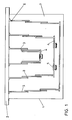
- FIG. 1 shows a section through a first embodiment of a hot water tank according to the invention
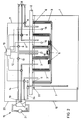
- Figure 2 shows the hot water tank shown in Figure 1 with a simple hot water control
- FIG. 3 shows a modified embodiment of the hot water tank according to the invention with the connection of a heating system.
- Fig. 1 denotes a fixed container, three insulated, telescopic tanks 3 are attached to the cover 2 of this container forming the hot water tank.
- the tanks can contract or expand in accordance with the addition or delivery of liquid, as will be explained in more detail with reference to the following figures.
- the inside tanks are each Via valves 5 arranged in the bottom surface 4, while the volume delimiting the outer, telescopic tank is connected via an overflow opening 6 in its upper edge region to a cold water reservoir 7 delimited by the jacket of the container 1.
- the three telescopic tanks arranged inside the container 1 are shown in their fully retracted position, in which the tanks 3 each have their smallest possible volume.
- the bottom valves 5 are opened by resting an outer tank on the inner tank, so that a liquid equalization between two adjacent tanks takes place automatically.
- an extraction line 8 opens into each of the tanks, which leads to consumers (not shown in more detail).
- Pumps and / or valves 9 are switched on in these extraction lines 8, control lines from a central control device 10 to these pumps or valves 9 being designated 11.
- the control unit 10 also controls pumps or valves 13 in supply lines 14 via control lines 12, via which heated water from a heat source 15 is conducted into the individual tanks in accordance with the temperature of this heated water.
- the temperature distribution in the individual tanks is such that the highest temperature prevails in the inner tank and a lower temperature prevails in the outer tanks.
- heat sensors 16 are arranged in these, which are also connected to the control unit 10 via lines 17.
- the device in the present case comprises a heat exchanger 25, to which water is supplied from the cold water reservoir 7 of the container via a line 18, which after heating up as a function of the temperature determined with the temperature sensor 19 via the supply lines 14 is one of the Tanks fed becomes.
- the temperature sensor 19 is also connected to the control unit 10 via a line 20.
- a solar energy system, a heat pump or a fuel boiler 21 can be used as the energy source for the heat exchanger 25.
- the liquid level in the cold water reservoir 7 is kept at a constant value via a float valve 22, which float valve is a flow valve. controls a pump 23 in a supply line 24.
- the reference symbols of the preceding figure have been retained for the same components.
- a heating system is also provided in this embodiment.
- the central control device 10 enables different control and removal processes.
- water from the heat exchanger 25 is introduced into the corresponding tank via the feed lines 14, the temperature in the individual tanks again being checked via the temperature sensors 16.
- a corresponding temperature gradient can be set via the control device by means of a programmable temperature difference between adjacent tanks. In connection with the use of a Heinz system, for example, a temperature difference of 15 ° C between individual tanks has proven to be favorable.
- the inner tanks When using a solar system 26 to supply the heat exchanger 25, the inner tanks in each case expand by appropriate hot water supply on fair weather days, since water taken from the cold water reservoir 7 via the line 18 is heated and fed into the respective inner tank.
- the maximum volume of the hot water tank designated 29 in this exemplary embodiment is reached, the bottom surface 4 of this innermost tank sits on the bottom surface the surrounding this innermost tank and designated 30, so that a connection between these two tanks is made via the bottom valve 5 and hot water flows from the innermost tank into the surrounding warm water tank.
- the bottom valves 5 With further supply of warm water, after the warm water tank 30 has been completely filled, its bottom valves 5 are also opened by sitting on the bottom surface of the further tank designated 31 and thus overflowing with liquid.
- the state shown in FIG. 3 is obtained, which corresponds to a storage of a maximum possible amount of heat or energy.
- the temperatures which can be achieved in this way in the inner tanks are sufficient to operate a low-temperature heating system, indicated schematically at 32, and a schematic radiator system, indicated at 33.
- hot water can be provided from the tank 30 and thus also from the innermost tank 29, if necessary via a mixer 34 and into the outer one to redirect tank 31 at a lower temperature.
- the mixer 34 is in turn controlled by the central control device 10 via a control line 35.
- the water in these heating systems can also be heated accordingly in the heat exchanger 25, whereby in addition to the solar energy system 26, a heat pump 27 and / or a fuel boiler 28 can be provided.
- a heat pump 27 and / or a fuel boiler 28 can be provided at corresponding temperatures in the heating systems 32 and 33.
- the hot water stored in these tanks can also be heated via the coil systems 37 and 38 immersed in the tanks 29 and 30.
- the heat pump designated 27 is advantageously fed from the tank 31 via the extraction line 39 and an optionally provided mixer 40, the return line 41 of the heat pump opening into the cold water reservoir 7.
Landscapes
- Engineering & Computer Science (AREA)
- Physics & Mathematics (AREA)
- Thermal Sciences (AREA)
- Chemical & Material Sciences (AREA)
- Combustion & Propulsion (AREA)
- Mechanical Engineering (AREA)
- General Engineering & Computer Science (AREA)
- Heat-Pump Type And Storage Water Heaters (AREA)
Applications Claiming Priority (2)
| Application Number | Priority Date | Filing Date | Title |
|---|---|---|---|
| AT57393 | 1993-03-23 | ||
| AT573/93 | 1993-03-23 |
Publications (2)
| Publication Number | Publication Date |
|---|---|
| EP0617237A2 true EP0617237A2 (fr) | 1994-09-28 |
| EP0617237A3 EP0617237A3 (fr) | 1995-03-08 |
Family
ID=3494186
Family Applications (1)
| Application Number | Title | Priority Date | Filing Date |
|---|---|---|---|
| EP94890061A Withdrawn EP0617237A3 (fr) | 1993-03-23 | 1994-03-22 | Accumulateur d'eau chaude télescopique avec régulation. |
Country Status (1)
| Country | Link |
|---|---|
| EP (1) | EP0617237A3 (fr) |
Cited By (2)
| Publication number | Priority date | Publication date | Assignee | Title |
|---|---|---|---|---|
| NL1017998C2 (nl) * | 2001-05-04 | 2002-11-05 | Noble Products Twente B V | Inrichting en werkwijze voor warmteopslag en toewijzing. |
| CN119100028A (zh) * | 2024-10-11 | 2024-12-10 | 福建誉泉环保设备有限公司 | 空气源热泵用储水罐及其控制方法 |
Family Cites Families (4)
| Publication number | Priority date | Publication date | Assignee | Title |
|---|---|---|---|---|
| CA1038176A (fr) * | 1975-04-01 | 1978-09-12 | James W.S. Rose | Systeme d'entreposage thermique |
| DE2724416A1 (de) * | 1977-05-28 | 1978-12-07 | Battelle Institut E V | Speicherelement fuer fluessige waermetraeger in heizanlagen |
| DE2749714A1 (de) * | 1977-11-07 | 1979-05-23 | Walter Dipl Ing Zimmermann | Waermespeicher |
| US4137900A (en) * | 1977-11-23 | 1979-02-06 | Brautigam Robert F | Solar heating system |
-
1994
- 1994-03-22 EP EP94890061A patent/EP0617237A3/fr not_active Withdrawn
Cited By (2)
| Publication number | Priority date | Publication date | Assignee | Title |
|---|---|---|---|---|
| NL1017998C2 (nl) * | 2001-05-04 | 2002-11-05 | Noble Products Twente B V | Inrichting en werkwijze voor warmteopslag en toewijzing. |
| CN119100028A (zh) * | 2024-10-11 | 2024-12-10 | 福建誉泉环保设备有限公司 | 空气源热泵用储水罐及其控制方法 |
Also Published As
| Publication number | Publication date |
|---|---|
| EP0617237A3 (fr) | 1995-03-08 |
Similar Documents
| Publication | Publication Date | Title |
|---|---|---|
| DE102010056370A1 (de) | Vorrichtung zur Steigerung der Effizienz einer Wärmepumpe bei der Brauchwassererzeugung | |
| DE2854999A1 (de) | Waermeuebertrager | |
| DE2851169C2 (de) | Wassererhitzer | |
| DE2651722A1 (de) | Verfahren und vorrichtung zur speisung einer anlage zur erzeugung und verteilung von einem dampf, der zur bildung einer ergaenzenden fluessigkeit kondensiert werden kann | |
| DE2947995A1 (de) | Heizwasserspeicher | |
| DE2804748C2 (de) | Wärme-isolierter Behälter für warmes Wasser o.a. Flüssigkeiten | |
| EP0518369B1 (fr) | Accumulateur stratifié | |
| DE2721173A1 (de) | Waermespeicher | |
| EP0617237A2 (fr) | Accumulateur d'eau chaude télescopique avec régulation | |
| DE60211816T2 (de) | Thermosiphon-Wärmespeichervorrichtung | |
| DE3044079C2 (de) | Warmwasserspeicher | |
| DE19504730C1 (de) | Warmwasserbereitungsanlage nach dem Durchflußprinzip mit Leistungsbegrenzung | |
| DE9315785U1 (de) | Multivalente Heizungsanlage | |
| DE3305041C2 (fr) | ||
| DE1299393B (de) | Warmwassererzeuger, insbesondere Heizwassererzeuger | |
| DE4429838A1 (de) | Vorrichtung zur Warmwassererzeugung mittels Solarenergie | |
| DE29706808U1 (de) | Pufferspeicher und Wärmesammel- und Verteilsystem mit einem Pufferspeicher | |
| DE10312520B4 (de) | Verfahren zum Betrieb eines solargekoppelten Wärmeträgerkreislaufes | |
| EP3106763A1 (fr) | Ballon d'eau chaude sanitaire et installation de distribution d'eau chaude dotee d'un ballon d'eau chaude sanitaire | |
| DE3828396A1 (de) | Vorrichtung zum erwaermen des waermetraegers eines heizkreislaufes und von brauchwasser | |
| DE102012008495A1 (de) | Vorrichtung zur Pufferspeicherung von Kälte- oder Wärmeenergie, Energiemanagementsystem mit der Vorrichtung und Verfahren zum Betreiben des Energiemanagementsystems | |
| DE4241384A1 (en) | Vehicular heater with storage for power unit contact - incorporates jet pump delivering liq. with heat recovered from exhaust to heat exchanger in passenger space | |
| DE102007044165A1 (de) | Vorrichtung zum Betrieb von Motoranlagen mit Pflanzenöl | |
| DE202016005844U1 (de) | Wärmespeicher mit Warmwasser-Wärmetauscher | |
| CH655376A5 (de) | Heizanlage zur warmwasserbereitung. |
Legal Events
| Date | Code | Title | Description |
|---|---|---|---|
| PUAI | Public reference made under article 153(3) epc to a published international application that has entered the european phase |
Free format text: ORIGINAL CODE: 0009012 |
|
| AK | Designated contracting states |
Kind code of ref document: A2 Designated state(s): AT BE CH DE DK ES FR GB GR IE IT LI NL PT SE |
|
| RAX | Requested extension states of the european patent have changed |
Free format text: SI PAYMENT 940409 |
|
| PUAL | Search report despatched |
Free format text: ORIGINAL CODE: 0009013 |
|
| AK | Designated contracting states |
Kind code of ref document: A3 Designated state(s): AT BE CH DE DK ES FR GB GR IE IT LI NL PT SE |
|
| STAA | Information on the status of an ep patent application or granted ep patent |
Free format text: STATUS: THE APPLICATION IS DEEMED TO BE WITHDRAWN |
|
| 18D | Application deemed to be withdrawn |
Effective date: 19950909 |