EP0617246A2 - Regel- und Steuergerät - Google Patents
Regel- und Steuergerät Download PDFInfo
- Publication number
- EP0617246A2 EP0617246A2 EP94104362A EP94104362A EP0617246A2 EP 0617246 A2 EP0617246 A2 EP 0617246A2 EP 94104362 A EP94104362 A EP 94104362A EP 94104362 A EP94104362 A EP 94104362A EP 0617246 A2 EP0617246 A2 EP 0617246A2
- Authority
- EP
- European Patent Office
- Prior art keywords
- housing part
- lower housing
- housing
- circular sector
- front surface
- Prior art date
- Legal status (The legal status is an assumption and is not a legal conclusion. Google has not performed a legal analysis and makes no representation as to the accuracy of the status listed.)
- Granted
Links
Images
Classifications
-
- F—MECHANICAL ENGINEERING; LIGHTING; HEATING; WEAPONS; BLASTING
- F24—HEATING; RANGES; VENTILATING
- F24H—FLUID HEATERS, e.g. WATER OR AIR HEATERS, HAVING HEAT-GENERATING MEANS, e.g. HEAT PUMPS, IN GENERAL
- F24H9/00—Details
- F24H9/20—Arrangement or mounting of control or safety devices
Definitions
- the invention relates to a regulating and control device for, in particular, heating boilers, comprising a pivotably mounted housing with setting and display elements arranged in its visible front surface.
- Regulating and control devices of the type mentioned are generally known and in use, so that no special printed evidence is required in this regard.
- the pivotability of such devices is provided in order to be able to adjust the front surface to the most favorable viewing angle.
- the pivotability is achieved in that the housing is rotatably mounted laterally on bases which are themselves fastened in a suitable manner on the housing of the boiler in question. If the cable connection from the boiler to the device housing is not inserted through the base and the swivel axes into the device housing, which is correspondingly complex, the cable routing extends freely between the device housing and the boiler housing, a problem that does not exist if the device housing is fixed is installed on the boiler housing. Here, however, the front surface cannot be set visually.
- the invention has for its object to improve regulating and control devices of the generic type in such a way that with its housing, that is to say without a lateral base, it can be installed firmly on the boiler housing on the one hand, but the front surface should nevertheless be visibly adjustable.
- the housing is formed from a lower housing part and from a tube-like stop-limited swiveling in and out in this, circular sector-shaped second cross-section housing part having the front surface.
- the electronics can be easily arranged and accommodated in the lower housing part and wired with the setting and display elements of the front surface on the swiveling housing part, i.e. the wiring is completely hidden in both housing parts.
- the upper and lower edges of the engagement opening in the lower housing part are adapted to the arc shape of the upper and lower end faces of the circular sector-shaped second housing part.
- a seal being arranged in a further embodiment in the gaps between the opening edges of the lower housing part and the upper and lower end faces and the circular sector-shaped side walls of the housing part, for which a polyamide-flocked flange band is advantageously provided, that not only seals well, but also prevents squeaking or abrasion noises when adjusting the second housing part.
- the seal is provided in particular in order to prevent moisture from penetrating into the interior of the housing, which could precipitate at the top and drip onto the electronic elements located at the bottom.
- the engagement opening is arranged in a plane running at 45 ° to the horizontal base surface of the lower housing part, and the arc length of the upper end surface is at least 45 °. This allows the pivoting housing part to be continuously adjusted over an arc length of at least 90 °.
- the lower housing part is provided with a removable cover.
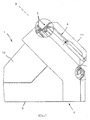
- the regulating and control device consists, in a known manner, of a pivotably mounted housing with adjustment and display elements arranged in its front face 4, but here and as shown, the housing 1 consists of a lower housing part 2 and a tube-like stop-limited swiveling in and out of it , in cross-section circular sector-shaped, second, the front surface 4 having housing part 3 is formed.
- the housing 1 consists of a lower housing part 2 and a tube-like stop-limited swiveling in and out of it , in cross-section circular sector-shaped, second, the front surface 4 having housing part 3 is formed.
- stroke-limited reference is made to the positions marked with A.
- the upper and lower edges 5 of the engagement opening 6 in the lower housing part 2 are adapted to the arc shape of the upper and lower end faces 7 of the circular sector-shaped second housing part 3, the gaps between the opening edges of the lower housing part 2 and the end surfaces 7 and Side walls 7 'of the housing part 3 in the shape of a sector of a circle, a seal 8 is arranged and this is designed in the form of a polyamide-flocked flange band.
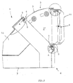
- the engagement opening 6 is arranged in a plane E which extends approximately at 45 ° to the horizontal base surface 9 of the lower housing part 2, the arc length of the upper end surface 7 also being approximately 45 °, so that the vertical position of the front surface 4 shown is thus obtained (see Fig. 2).
- a removable cover, with which the side flanks of the lower housing part 2 are also partially covered, is designated by 10 and a transparent cover for the front surface by 11.
Landscapes
- Engineering & Computer Science (AREA)
- General Engineering & Computer Science (AREA)
- Chemical & Material Sciences (AREA)
- Thermal Sciences (AREA)
- Combustion & Propulsion (AREA)
- Mechanical Engineering (AREA)
- Physics & Mathematics (AREA)
- Devices For Indicating Variable Information By Combining Individual Elements (AREA)
- Pivots And Pivotal Connections (AREA)
- Vehicle Body Suspensions (AREA)
- Massaging Devices (AREA)
- Indication Of The Valve Opening Or Closing Status (AREA)
- Selective Calling Equipment (AREA)
- Lock And Its Accessories (AREA)
- Lifting Devices For Agricultural Implements (AREA)
Abstract
Description
- Die Erfindung betrifft ein Regel- und Steuergerät für insbesondere Heizkessel, bestehend aus einem schwenkbar gelagerten Gehäuse mit in dessen sichtseitiger Frontfläche angeordneten Einstell- und Anzeigeelementen.
- Regel- und Steuergeräte der genannten Art sind allgemein bekannt und in Benutzung, so daß es diesbezüglich an sich keines besonderen druckschriftlichen Nachweises bedarf. Verwiesen sei nur bspw. auf die EP-A-0 393 046. Die Schwenkbarkeit solcher Geräte ist vorgesehen, um die Frontfläche auf den jeweils günstigsten Sichtwinkel einstellen zu können. Erreicht wird die Schwenkbarkeit dadurch, daß das Gehäuse seitlich an Sockeln drehbar gelagert ist, die selbst in geeigneter Weise auf dem Gehäuse des betreffenden Heizkessels befestigt sind. Sofern die Kabelverbindung aus dem Heizkessel mit dem Gerätegehäuse nicht durch die Sockel und die Schwenkachsen in das Gerätegehäuse eingeführt werden, was entsprechend aufwendig ist, erstreckt sich die Kabelführung frei zwischen Gerätegehäuse und Heizkesselgehäuse, ein Problem, das dann nicht gegeben ist, wenn das Gerätegehäuse fest auf dem Heizkesselgehäuse installiert wird. Hierbei kann aber die Frontfläche nicht sichtgünstig eingestellt werden.
- Der Erfindung liegt die Aufgabe zugrunde, Regel- und Steuergeräte der gattungsgemäßen Art dahingehend zu verbessern, daß dieses mit seinem Gehäuse, also ohne seitliche Sockel, einerseits fest auf dem Heizkesselgehäuse installiert werden kann, dabei aber die Frontfläche trotzdem sichtgünstig einstellbar sein soll.
- Diese Aufgabe ist mit einem Regel- und Steuergerät der eingangs genannten Art nach der Erfindung dadurch gelöst, daß das Gehäuse aus einem Gehäuseunterteil und aus einem in dieses tubusartig anschlagbegrenzt ein- und ausschwenkbaren, im Querschnitt kreissektorförmigen, zweiten, die Frontfläche aufweisenden Gehäuseteil gebildet ist.
- Abgesehen davon, daß eine solche neuartige Ausführungsform dem Gesamtdesign eines Heizkessels zugute kommt, ist damit die gestellte Aufgabe in eleganter Weise gelöst, verbunden mit dem Vorteil, daß es weder freiliegende Kabelführungen gibt, noch ein besonderer Aufwand bezüglich der Kabelführung getrieben werden muß, um dieses der Sicht bzw. äußeren Beeinträchtigungen zu entziehen.
- Die Elektronik ist dabei problemlos im unteren Gehäuseteil anzuordnen und unterzubringen und mit den Einstell- und Anzeigeelementen der am schwenkbaren Gehäuseteil befindlichen Frontfläche zu verkabeln, d.h., die Verkabelung befindet sich völlig versteckt in beiden Gehäuseteilen.
- Vorteilhafte Ausgestaltungen bestehen in Folgendem:
Die oberen und unteren Ränder der Eingriffsöffnung im Gehäuseunterteil sind an die Bogenform der oberen und unteren Abschlußflächen des kreissektorförmigen zweiten Gehäuseteils angepaßt ausgebildet. Dadurch ergibt sich eine saubere Schwenkführung des zweiten Gehäuseteils, wobei in weiterer Ausgestaltung in den Spalten zwischen den Öffnungsrändern des Gehäuseunterteils und den oberen und unteren Abschlußflächen und den kreissektorförmigen Seitenwänden des Gehäuseteils eine Dichtung angeordnet ist, für die vorteilhaft ein polyamid-beflocktes Flanschband vorgesehen ist, das nicht nur gut abdichtet, sondern auch Quietsch- bzw. Scheuergeräusche beim Verstellen des zweiten Gehäuseteils verhindert. Die Abdichtung ist insbesondere deshalb vorgesehen, um das Eindringen von Feuchtigkeit in das Gehäuseinnere zu vermeiden, die sich oben niederschlagen und auf die unten befindlichen Elektronikelemente abtropfen könnte. - Die Eingriffsöffnung ist in einer zur horizontalen Grundfläche des Gehäuseunterteiles unter 45° verlaufenden Ebene angeordnet, und die Bogenlänge der oberen Abschlußfläche beträgt mindestens 45°. Dadurch ist eine stufenlose Einstellungsmöglichkeit des schwenkbaren Gehäuseteiles über eine Bogenlänge von mindestens 90° gegeben.
- Um die Elektronik und die Verkabelung zur Frontfläche zugänglich zu halten, ist das untere Gehäuseteile mit einem abnehmbaren Deckel versehen.
- Das erfindungsgemäße Regel- und Steuergerät wird nachfolgend anhand der zeichnerischen Darstellung eines einzigen Ausführungsbeispieles näher erläutert.
- Es zeigt jeweils in Seitenansicht und teilweise im Schnitt
- Fig. 1
- das Gerät in Normalstellung und
- Fig. 2
- das Gerät mit ausgeschwenktem Geräteteil.
- Das Regel- und Steuergerät besteht in bekannter Weise aus einem schwenkbar gelagerten Gehäuse mit in dessen sichtseitiger Frontfläche 4 angeordneten Einstell- und Anzeigeelementen, wobei jedoch hier und gemäß Darstellung das Gehäuse 1 aus einem Gehäuseunterteil 2 und aus einem in dieses tubusartig anschlagbegrenzt ein- und ausschwenkbaren, im Querschnitt kreissektorförmigen, zweiten, die Frontfläche 4 aufweisenden Gehäuseteil 3 gebildet ist. Bezüglich "anschlagbegrenzt" wird auf die mit A bezeichneten Stellen verwiesen.
Wie aus den Schnittbereichsdarstellungen ersichtlich, sind die oberen und unteren Ränder 5 der Eingriffsöffnung 6 im Gehäuseunterteil 2 an die Bogenform der oberen und unteren Abschlußflächen 7 des kreissektorförmigen zweiten Gehäuseteils 3 angepaßt, wobei in den Spalten zwischen den Öffnungsrändern des Gehäuseunterteils 2 und den Abschlußflächen 7 und kreissektorförmigen Seitenwänden 7' des Gehäuseteils 3 eine Dichtung 8 angeordnet und diese in Form eines polyamid-beflockten Flanschbandes ausgebildet ist.
Ferner ist beim dargestellten Ausführungsbeispiel die Eingriffsöffnung 6 in einer zur horizontalen Grundfläche 9 des Gehäuseunterteils 2 etwa unter 45° verlaufenden Ebene E angeordnet, wobei die Bogenlänge der oberen Abschlußfläche 7 ebenfalls etwa 45° beträgt, so daß sich damit die dargestellte Vertikalstellung der Frontfläche 4 ergibt (siehe Fig. 2). - Ein abnehmbarer Deckel, mit dem auch die Seitenflanken des Gehäuseunterteiles 2 zum Teil mit erfaßt sind, ist mit 10 bezeichnet und eine transparente Abdeckhaube für die Frontfläche mit 11.
Claims (6)
- Regel- und Steuergerät für insbesondere Heizkessel, bestehend aus einem schwenkbar gelagerten Gehäuse (1) mit in dessen sichtseitiger Frontfläche (4) angeordneten Einstell- und Anzeigeelementen,
dadurch gekennzeichnet,
daß das Gehäuse (1) aus einem Gehäuseunterteil (2) und aus einem in dieses tubusartig anschlagbegrenzt ein- und ausschwenkbaren, im Querschnitt kreissektorförmigen, zweiten, die Frontfläche (4) aufweisenden Gehäuseteil (3) gebildet ist. - Gerät nach Anspruch 1,
dadurch gekennzeichnet,
daß die oberen und unteren Ränder (5) der Eingriffsöffnung (6) im Gehäuseunterteil (2) an die Bogenform der oberen und unteren Abschlußflächen (7) des kreissektorförmigen zweiten Gehäuseteils (3) angepaßt ausgebildet sind. - Gerät nach Anspruch 2,
dadurch gekennzeichnet,
daß in den Spalten zwischen den Öffnungsrändern des Gehäuseunterteils (2) und den Abschlußflächen (7) und kreissektorförmigen Seitenwänden (7') des Gehäuseteils (3) eine Dichtung (8) angeordnet ist. - Gerät nach Anspruch 3,
dadurch gekennzeichnet,
daß die Dichtung (8) in Form eines polyamid-beflockten Flanschbandes ausgebildet ist. - Gerät nach einem der Ansprüche 1 bis 4,
dadurch gekennzeichnet,
daß die Eingriffsöffnung (6) in einer zur horizontalen Grundfläche (9) des Gehäuseunterteiles (2) unter 45° ver laufenden Ebene (E) angeordnet ist und die Bogenlänge der oberen Abschlußfläche (7) mindestens 45° beträgt. - Gerät nach einem der Ansprüche 1 bis 5,
dadurch gekennzeichnet,
daß das Gehäuseunterteil (2) mit einem abnehmbaren Deckel (10) versehen ist.
Applications Claiming Priority (2)
| Application Number | Priority Date | Filing Date | Title |
|---|---|---|---|
| DE9304244U DE9304244U1 (de) | 1993-03-22 | 1993-03-22 | Regel- und Steuergerät |
| DE9304244U | 1993-03-22 |
Publications (3)
| Publication Number | Publication Date |
|---|---|
| EP0617246A2 true EP0617246A2 (de) | 1994-09-28 |
| EP0617246A3 EP0617246A3 (de) | 1995-02-01 |
| EP0617246B1 EP0617246B1 (de) | 1997-07-30 |
Family
ID=6890993
Family Applications (1)
| Application Number | Title | Priority Date | Filing Date |
|---|---|---|---|
| EP94104362A Expired - Lifetime EP0617246B1 (de) | 1993-03-22 | 1994-03-19 | Regel- und Steuergerät |
Country Status (3)
| Country | Link |
|---|---|
| EP (1) | EP0617246B1 (de) |
| AT (1) | ATE156253T1 (de) |
| DE (2) | DE9304244U1 (de) |
Cited By (3)
| Publication number | Priority date | Publication date | Assignee | Title |
|---|---|---|---|---|
| EP0921359A2 (de) | 1997-12-06 | 1999-06-09 | VIESSMANN WERKE GmbH & CO. | Heizkesselumschliessungsgehäuse mit Heizkreisreglergehäuse |
| NL1016284C2 (nl) * | 2000-09-27 | 2002-03-28 | Nefit Buderus B V | Verwarmingsinrichting met bedieningsmiddelen. |
| DE102004025927A1 (de) * | 2004-05-27 | 2006-03-23 | BSH Bosch und Siemens Hausgeräte GmbH | Elektrisches Haushaltsgerät, insbesondere Warmwasserbereiter, insbesondere Durchlauferhitzer |
Families Citing this family (3)
| Publication number | Priority date | Publication date | Assignee | Title |
|---|---|---|---|---|
| DE19508413C1 (de) * | 1995-03-09 | 1996-08-22 | Centra Buerkle Gmbh & Co | Regler |
| DE102007010921A1 (de) | 2007-03-05 | 2008-09-11 | Viessmann Werke Gmbh & Co Kg | Klappgehäuse |
| DE102007010920B3 (de) * | 2007-03-05 | 2008-06-19 | Viessmann Werke Gmbh & Co Kg | Klappgehäuse |
Family Cites Families (4)
| Publication number | Priority date | Publication date | Assignee | Title |
|---|---|---|---|---|
| AT300272B (de) * | 1968-05-21 | 1972-07-25 | Viessmann Hans | Reglerkasten |
| DE3404256A1 (de) * | 1984-02-07 | 1985-08-08 | Bosch Siemens Hausgeraete | Elektrisches haushaltgeraet |
| DE8811232U1 (de) * | 1988-09-06 | 1990-01-04 | Petz, Günter, 8500 Nürnberg | Heizlüfter |
| IT1228736B (it) * | 1989-03-16 | 1991-07-03 | Smeg Spa | Pannello comandi per apparecchi domestici, elettrici o a gas, con frontalino arretrabile per l'accesso ai comandi. |
-
1993
- 1993-03-22 DE DE9304244U patent/DE9304244U1/de not_active Expired - Lifetime
-
1994
- 1994-03-19 DE DE59403505T patent/DE59403505D1/de not_active Expired - Fee Related
- 1994-03-19 EP EP94104362A patent/EP0617246B1/de not_active Expired - Lifetime
- 1994-03-19 AT AT94104362T patent/ATE156253T1/de not_active IP Right Cessation
Cited By (6)
| Publication number | Priority date | Publication date | Assignee | Title |
|---|---|---|---|---|
| EP0921359A2 (de) | 1997-12-06 | 1999-06-09 | VIESSMANN WERKE GmbH & CO. | Heizkesselumschliessungsgehäuse mit Heizkreisreglergehäuse |
| DE19754266A1 (de) * | 1997-12-06 | 1999-06-17 | Viessmann Werke Kg | Heizkreisreglergehäuse |
| EP0921359A3 (de) * | 1997-12-06 | 2001-05-16 | VIESSMANN WERKE GmbH & CO. | Heizkesselumschliessungsgehäuse mit Heizkreisreglergehäuse |
| NL1016284C2 (nl) * | 2000-09-27 | 2002-03-28 | Nefit Buderus B V | Verwarmingsinrichting met bedieningsmiddelen. |
| EP1193454A1 (de) * | 2000-09-27 | 2002-04-03 | Nefit Buderus B.V. | Heizgerät mit Bedienungsmitteln |
| DE102004025927A1 (de) * | 2004-05-27 | 2006-03-23 | BSH Bosch und Siemens Hausgeräte GmbH | Elektrisches Haushaltsgerät, insbesondere Warmwasserbereiter, insbesondere Durchlauferhitzer |
Also Published As
| Publication number | Publication date |
|---|---|
| EP0617246A3 (de) | 1995-02-01 |
| DE59403505D1 (de) | 1997-09-04 |
| DE9304244U1 (de) | 1993-05-27 |
| EP0617246B1 (de) | 1997-07-30 |
| ATE156253T1 (de) | 1997-08-15 |
Similar Documents
| Publication | Publication Date | Title |
|---|---|---|
| DE8815072U1 (de) | Beleuchtete Reguliervorrichtung zur Betätigung einer Belüftungseinrichtung o.dgl.in einem Kraftfahrzeug | |
| DE2827889A1 (de) | Schiebedach fuer kraftfahrzeuge | |
| EP0617246A2 (de) | Regel- und Steuergerät | |
| EP0010763B1 (de) | Rahmenprofil für Fenster- und Türrahmen bzw. für aufsetzbare Bedienungsfelder od. dgl. von Schalt- oder Verteilerschränken und dgl. | |
| DE10043656A1 (de) | Mittelkonsole für ein Kraftfahrzeug | |
| DE69609015T2 (de) | Einrastbarer Stützschaft für Seilrollen | |
| DE9307045U1 (de) | Befestigungsvorrichtung für eine Atemmaske an einem Schutzhelm | |
| DE3424330A1 (de) | Luftreinigungsgeraet, insbesondere dunstabzugshaube | |
| DE8812250U1 (de) | Bedienungsgerätehalterung für Rollstühle | |
| DE2840443C2 (de) | Vorrichtung zur Höheneinstellung eines starren Schiebedeckels | |
| DE8817098U1 (de) | Gehäuse für den Anschluß von Kommunikationssystemen | |
| DE19502343C2 (de) | Feuchtigkeitsabweisende Belüftungsvorrichtung für ein Gehäuse | |
| EP0200084A2 (de) | Fahrzeugdach mit einer einen Deckel aufnehmenden Dachkassette | |
| DE69905814T2 (de) | Verstellbare Eck-Verbindung für Kabelkanäle | |
| DE4231950C2 (de) | Gehäuse für die Aufnahme von Daten- und Kommunikations-Steckverbindungen in senkrechter oder geneigter Einbaulage | |
| DE20220848U1 (de) | Gehäuse oder Gestell mit einer Kabelführungsvorrichtung | |
| DE19821896B4 (de) | Abdeckblende für Rolladen-Gurtwickler | |
| DE4119393A1 (de) | Schwenkanordnung | |
| DE19529652C1 (de) | Steuergerät zur schwenkbaren Befestigung auf einer horizontalen Befestigungsfläche | |
| DE2643614C3 (de) | Vorrichtung zum Befestigen einer einen Anschlußstutzen aufweisenden Mastleuchte | |
| DE9301322U1 (de) | Blendschutz für Computerbildschirme | |
| DE2212531C3 (de) | Brillenbügel mit einstellbarer Länge | |
| DE2836168C3 (de) | Konsole zum Befestigen von Heizkörpern an einer Wand | |
| DE8903381U1 (de) | Höhenverstellbare Pendelleuchte | |
| DE69804703T2 (de) | Kanalverbindung |
Legal Events
| Date | Code | Title | Description |
|---|---|---|---|
| PUAI | Public reference made under article 153(3) epc to a published international application that has entered the european phase |
Free format text: ORIGINAL CODE: 0009012 |
|
| AK | Designated contracting states |
Kind code of ref document: A2 Designated state(s): AT BE CH DE FR IT LI NL |
|
| PUAL | Search report despatched |
Free format text: ORIGINAL CODE: 0009013 |
|
| AK | Designated contracting states |
Kind code of ref document: A3 Designated state(s): AT BE CH DE FR IT LI NL |
|
| 17P | Request for examination filed |
Effective date: 19950202 |
|
| 17Q | First examination report despatched |
Effective date: 19960209 |
|
| GRAG | Despatch of communication of intention to grant |
Free format text: ORIGINAL CODE: EPIDOS AGRA |
|
| GRAH | Despatch of communication of intention to grant a patent |
Free format text: ORIGINAL CODE: EPIDOS IGRA |
|
| GRAH | Despatch of communication of intention to grant a patent |
Free format text: ORIGINAL CODE: EPIDOS IGRA |
|
| ITF | It: translation for a ep patent filed | ||
| GRAA | (expected) grant |
Free format text: ORIGINAL CODE: 0009210 |
|
| AK | Designated contracting states |
Kind code of ref document: B1 Designated state(s): AT BE CH DE FR IT LI NL |
|
| REF | Corresponds to: |
Ref document number: 156253 Country of ref document: AT Date of ref document: 19970815 Kind code of ref document: T |
|
| REG | Reference to a national code |
Ref country code: CH Ref legal event code: NV Representative=s name: SCHMAUDER & WANN PATENTANWALTSBUERO, INHABER KLAUS Ref country code: CH Ref legal event code: EP |
|
| ET | Fr: translation filed | ||
| REF | Corresponds to: |
Ref document number: 59403505 Country of ref document: DE Date of ref document: 19970904 |
|
| PLBI | Opposition filed |
Free format text: ORIGINAL CODE: 0009260 |
|
| 26 | Opposition filed |
Opponent name: BUDERUS HEIZTECHNIK GMBH, WETZLAR TE-PATENTWESEN Effective date: 19980303 |
|
| PLBF | Reply of patent proprietor to notice(s) of opposition |
Free format text: ORIGINAL CODE: EPIDOS OBSO |
|
| NLR1 | Nl: opposition has been filed with the epo |
Opponent name: BUDERUS HEIZTECHNIK GMBH, WETZLAR TE-PATENTWESEN |
|
| PLBF | Reply of patent proprietor to notice(s) of opposition |
Free format text: ORIGINAL CODE: EPIDOS OBSO |
|
| PLBF | Reply of patent proprietor to notice(s) of opposition |
Free format text: ORIGINAL CODE: EPIDOS OBSO |
|
| PGFP | Annual fee paid to national office [announced via postgrant information from national office to epo] |
Ref country code: BE Payment date: 19990303 Year of fee payment: 6 |
|
| PGFP | Annual fee paid to national office [announced via postgrant information from national office to epo] |
Ref country code: CH Payment date: 19990326 Year of fee payment: 6 |
|
| PGFP | Annual fee paid to national office [announced via postgrant information from national office to epo] |
Ref country code: NL Payment date: 19990331 Year of fee payment: 6 Ref country code: FR Payment date: 19990331 Year of fee payment: 6 Ref country code: DE Payment date: 19990331 Year of fee payment: 6 Ref country code: AT Payment date: 19990331 Year of fee payment: 6 |
|
| PLBO | Opposition rejected |
Free format text: ORIGINAL CODE: EPIDOS REJO |
|
| PLBN | Opposition rejected |
Free format text: ORIGINAL CODE: 0009273 |
|
| STAA | Information on the status of an ep patent application or granted ep patent |
Free format text: STATUS: OPPOSITION REJECTED |
|
| PG25 | Lapsed in a contracting state [announced via postgrant information from national office to epo] |
Ref country code: AT Free format text: LAPSE BECAUSE OF NON-PAYMENT OF DUE FEES Effective date: 20000319 |
|
| PG25 | Lapsed in a contracting state [announced via postgrant information from national office to epo] |
Ref country code: LI Free format text: LAPSE BECAUSE OF NON-PAYMENT OF DUE FEES Effective date: 20000331 Ref country code: CH Free format text: LAPSE BECAUSE OF NON-PAYMENT OF DUE FEES Effective date: 20000331 Ref country code: BE Free format text: LAPSE BECAUSE OF NON-PAYMENT OF DUE FEES Effective date: 20000331 |
|
| 27O | Opposition rejected |
Effective date: 19991219 |
|
| NLR2 | Nl: decision of opposition | ||
| BERE | Be: lapsed |
Owner name: VIESSMANN WERKE G.M.B.H. & CO. Effective date: 20000331 |
|
| PG25 | Lapsed in a contracting state [announced via postgrant information from national office to epo] |
Ref country code: NL Free format text: LAPSE BECAUSE OF NON-PAYMENT OF DUE FEES Effective date: 20001001 |
|
| REG | Reference to a national code |
Ref country code: CH Ref legal event code: PL |
|
| PG25 | Lapsed in a contracting state [announced via postgrant information from national office to epo] |
Ref country code: FR Free format text: LAPSE BECAUSE OF NON-PAYMENT OF DUE FEES Effective date: 20001130 |
|
| NLV4 | Nl: lapsed or anulled due to non-payment of the annual fee |
Effective date: 20001001 |
|
| REG | Reference to a national code |
Ref country code: FR Ref legal event code: ST |
|
| PG25 | Lapsed in a contracting state [announced via postgrant information from national office to epo] |
Ref country code: DE Free format text: LAPSE BECAUSE OF NON-PAYMENT OF DUE FEES Effective date: 20010103 |
|
| PG25 | Lapsed in a contracting state [announced via postgrant information from national office to epo] |
Ref country code: IT Free format text: LAPSE BECAUSE OF NON-PAYMENT OF DUE FEES;WARNING: LAPSES OF ITALIAN PATENTS WITH EFFECTIVE DATE BEFORE 2007 MAY HAVE OCCURRED AT ANY TIME BEFORE 2007. THE CORRECT EFFECTIVE DATE MAY BE DIFFERENT FROM THE ONE RECORDED. Effective date: 20050319 |