EP0921359A2 - Heizkesselumschliessungsgehäuse mit Heizkreisreglergehäuse - Google Patents
Heizkesselumschliessungsgehäuse mit Heizkreisreglergehäuse Download PDFInfo
- Publication number
- EP0921359A2 EP0921359A2 EP98122829A EP98122829A EP0921359A2 EP 0921359 A2 EP0921359 A2 EP 0921359A2 EP 98122829 A EP98122829 A EP 98122829A EP 98122829 A EP98122829 A EP 98122829A EP 0921359 A2 EP0921359 A2 EP 0921359A2
- Authority
- EP
- European Patent Office
- Prior art keywords
- housing
- housing part
- parts
- open
- boiler
- Prior art date
- Legal status (The legal status is an assumption and is not a legal conclusion. Google has not performed a legal analysis and makes no representation as to the accuracy of the status listed.)
- Granted
Links
- 238000010438 heat treatment Methods 0.000 title claims abstract description 16
- 238000011161 development Methods 0.000 description 2
- 230000018109 developmental process Effects 0.000 description 2
- 230000010354 integration Effects 0.000 description 2
- 241000208199 Buxus sempervirens Species 0.000 description 1
- 238000010276 construction Methods 0.000 description 1
- 230000001419 dependent effect Effects 0.000 description 1
- 230000002349 favourable effect Effects 0.000 description 1
- 238000004806 packaging method and process Methods 0.000 description 1
- 238000005192 partition Methods 0.000 description 1
- 230000035515 penetration Effects 0.000 description 1
- 230000001681 protective effect Effects 0.000 description 1
- 238000000926 separation method Methods 0.000 description 1
Images


Classifications
-
- F—MECHANICAL ENGINEERING; LIGHTING; HEATING; WEAPONS; BLASTING
- F24—HEATING; RANGES; VENTILATING
- F24H—FLUID HEATERS, e.g. WATER OR AIR HEATERS, HAVING HEAT-GENERATING MEANS, e.g. HEAT PUMPS, IN GENERAL
- F24H9/00—Details
- F24H9/02—Casings; Cover lids; Ornamental panels
-
- F—MECHANICAL ENGINEERING; LIGHTING; HEATING; WEAPONS; BLASTING
- F24—HEATING; RANGES; VENTILATING
- F24H—FLUID HEATERS, e.g. WATER OR AIR HEATERS, HAVING HEAT-GENERATING MEANS, e.g. HEAT PUMPS, IN GENERAL
- F24H9/00—Details
- F24H9/20—Arrangement or mounting of control or safety devices
Definitions
- the invention relates to a boiler enclosure housing with heating circuit controller housing according to the preamble of the claim 1
- Heating circuit controller housing of the type mentioned are on Boiler enclosures housings, for example. known from EP 0 617 246.
- the special one there The housing parts can be swiveled in the Control and display elements arranged on the front surface to set the operator's most favorable viewing angle. This remains of minor importance Device easily accessible within the housing arranged electrical and electronic components.
- this is also relevant Control unit known the front surface with one with respect to the housing up, down or laterally swiveling or sliding, all in the Display and control elements arranged on the front surface covering, opaque cover is provided, which on its outer visible surface is an operating and / or Has fault indicator element. Also with this control device is easy accessibility of the arranged in the housing electrical and electronic components not considered.
- EP 0 617 246 Apart from the control device after the entry mentioned EP 0 617 246 is that according to EP 0 341 751 practical for the most widely used construction principle Housing, i.e. box with a flat lid for arrangement the front surface, whereby, as far as is known, only with quite a bit Effort in case of need to the electrical / electronic "Offal" can be approached and usually still In addition, when the housing is open, there is no easy access consists.
- the invention has for its object a boiler enclosure housing with its heating circuit controller housing of the type mentioned in a simple way to improve and train both housing represent structures that can be integrated relative to one another and but the inside of the heating circuit controller housing arranged electrical and electronic components easy to open housing despite protective Integration and direct cable access from the boiler enclosure housing remain easily accessible.
- the boiler enclosure housing according to the invention its heating circuit controller housing and its advantageous further developments are subsequently based on the graphic Representation of exemplary embodiments explained in more detail.
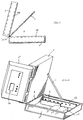
- the heating circuit controller housing with operating and display elements BA still consists of two housing parts 1, 2 which are pivotally assigned to one another and in which a power supply unit SN and heating circuit control electronics RE are accommodated.
- the boiler enclosure housing according to the invention with its heating circuit controller housing that of the two housing parts 1, 2, which essentially correspond in shape and volume, one of which is the pivotable closure which is articulated on the other housing part 1 and which is open for the housing part 2 which can be pivoted open, forms box-shaped housing part 1, the parting plane E between the two housing parts 1, 2 extends horizontally and the housing part 1 is adapted to its box shape and allows the removal by pivoting or lifting the housing part 2 recess 12 on the boiler housing housing 10, the operating and display elements BA are arranged in the long side surfaces 3 of the box-shaped housing parts 1, 2 to be installed on the visible side, ie towards the boiler front surface.
- the articulation of the second housing part 2 by hinge 4 on the first housing part 1 is preferred, namely on the
- housing part 2 To easily replace the housing part 2 if necessary can or to on this in a comfortable overhead position the two are able to work at a work table Housing parts 1, 2 advantageous with a light in itself separable hinge 4 connected to each other, which in Fig. 2 is only indicated by dashed lines and none closer Explanation is required because such separable hinges or Joints in various forms per se are known.
- an open support 5 (see FIG. 2) is arranged, the suitably adjustable on the edge of the Housing part 1, as shown, is guided.
- this open support 5 as a cable duct be trained by the by cable Connection between the in the lower housing part 1 arranged power supply (if necessary also electronics for the Heating control) and a cable connection strip KL and the Operating electronics in the housing part 2 is produced.
- the controller housing is with its housing part 1, as in 6 shown in a corresponding recess 12 of the Boiler enclosure housing 10 recessed, i.e., that Housing part 1 forms the housing base seated in housing 10, wherein the housing part 2 is pivoted through 90 ° can be, as is also the case, for example, with an arrangement according to Fig.7 is possible, according to which the controller housing in a corresponding recess 12 one to the enclosure 10 belonging console 13 on the front surface of the Boiler enclosure 10 is inserted.
- housing part 2 is also like the other is designed as an open box, which is preferred are the whole "innards" of both housing parts 1, 2 a 180 ° opening position possible there clearly and easily accessible.
- the particularly conveniently accessible and for the inclusion of the Power supply unit is also designated as Interchangeable electronic card for heating control arranged with.
- a consequent separation of the two electrical ones Components in their respective housing parts 1.2 however also possible.
- the housing parts 1,2 slightly snapped Intermediate floors 8 (only as broken triangles in Fig.2 indicated) can be provided, or it can also, as in Fig.3 shown between the two against each other open housing parts 1,2 one around the common Swivel axis
- a rotatable partition plate 7 are provided which, also light on one and the other housing part lockable, depending on requirements after opening the whole Housing created on one or the other housing part 1,2 and the opp. even as a carrier for the electronics of the Control panel can be used.
- the housing part 1 forms the base for the entire controller housing, this is, which is not particularly shown, provided in one of its non-visible walls with cable penetrations or plug-in openings, on the one hand for the mains connection and on the other hand for current paths involved in the control, but up to must be led to the control electronics RE.
- a flexible broadband cable 9 is provided between the two housing parts 1, 2, which is indicated by dash-dotted lines in FIG. 3 and is used if the cable routing does not, as previously explained, is advantageous and in order not to impair the overall clarity of the whole. the open support 5 is used.
- a special embodiment for the operating part or the housing part 2 is shown in FIG.
- a drawer housing 2 ' which can be inserted into the housing and in which the operating electronics are located, is arranged in the box-shaped, pivotable housing part 2. As shown, this drawer housing 2 'is pivotally assigned to the housing part 2, the operating and display elements BA being arranged in the bottom surface F' of the drawer housing 2 '.
- the distance ability through liftability of the housing part 2 of the housing part 1 simple can be achieved in that the housing part 2 in suitably detachable on the housing part 1 is attached (not particularly shown, since without further imaginable), the distance can also can be realized in that the two housing parts 1,2 by means of so-called and guided in transverse guides 11 ' Parallel link 11 are interconnected, as shown in 5B is shown schematically.
- Fig. 5A, B can advantageously be provided on the upper housing part 2 to form its surface 2 "as a hinged lid, what makes this housing part 2 directly accessible, without having to open it by swiveling or lifting. If the housing part 2 is not a closed, has an integral bottom, can easily be a support plate or circuit board to hold the electronics in the housing part 2 to be ordered.
Landscapes
- Engineering & Computer Science (AREA)
- Physics & Mathematics (AREA)
- Thermal Sciences (AREA)
- Chemical & Material Sciences (AREA)
- Combustion & Propulsion (AREA)
- Mechanical Engineering (AREA)
- General Engineering & Computer Science (AREA)
- Casings For Electric Apparatus (AREA)
- Devices For Indicating Variable Information By Combining Individual Elements (AREA)
- Central Heating Systems (AREA)
Abstract
Description
Vorteilhafte Weiterbildungen ergeben sich nach den abhängigen Ansprüchen.
Außerdem ist unter "Distanzierbarkeit durch Anhebbarkeit" auch zu verstehen die einfache Aufsetzbarkeit des zweiten Gehäuseteiles auf den ersten Gehäuseteil.
- Fig. 1
- perspektivisch das Reglergehäuse im geschlossenen Zustand;
- Fig. 2
- perspektivisch das Reglergehäuse gemäß Fig.1 in geöffnetem Zustand;
- Fig. 3
- das Reglergehäuse geöffnet in sichtseitiger Ansicht;
- Fig. 4 Fig.5A,B
- perspektivisch eine besondere Ausführungsform schematisch und perspektivisch andere Ausführungsformen der Verbindung zwischen den Reglergehäuseteilen und
- Fig. 6,7
- perspektivisch Anordnungsbeispiele von Reglergehäusen am Heizkesselumschließungsgehäuse.
Orientiert an den Darstellungen ist für das erfindungsgemäße Heizkesselumschließungsgehäuse mit seinem Heizkreisreglergehäuse wesentlich, daß von den beiden sich in Form und Volumen im wesentlichen entsprechenden Gehäuseteilen 1, 2 der eine den aufschwenkbaren, am anderen Gehäuseteil 1 angelenkten Verschluß für den gegen den aufschwenkbaren Gehäuseteil 2 offenen, kastenförmigen Gehäuseteil 1 bildet, die Trennebene E zwischen den beiden Gehäuseteilen 1,2 horizontal erstreckt und der Gehäuseteil 1 in einer seiner Kastenform angepaßten und die Distanzierbarkeit durch Aufschwenk- oder Anhebbarkeit des Gehäuseteiles 2 zulassende Ausnehmung 12 am Heizkesselumschließungsgehäuse 10 eingelassen ist, wobei die Bedien- und Anzeigeelemente BA in den sichtseitig, d.h., zur Heizkesselfrontfläche hin zu installierenden Längsseitenflächen 3 der kastenförmigen Gehäuseteile 1,2 angeordnet sind.
Bevorzugt wird beim Ganzen die Anlenkung des zweiten Gehäuseteiles 2 per Scharnier 4 am ersten Gehäuseteil 1, und zwar an den Schmalseiten S.
Eine besondere Ausführungsform für das Bedienteil bzw. das Gehäuseteil 2 ist in Fig.4 dargestellt. Hiernach ist im kastenförmig ausgebildeten, aufschwenkbaren Gehäuseteil 2 ein in dieses passend einschiebbares Schubladengehäuse 2' angeordnet, in dem sich die Bedienelektronik befindet. Dieses Schubladengehäuse 2' ist dem Gehäuseteil 2 , wie dargestellt, schwenkbar zugeordnet, wobei die Bedien- und Anzeigeelemente BA in der Bodenfläche F' des Schubladengehäuses 2' angeordnet sind.
Claims (10)
- Heizkesselumschließungsgehäuse mit Heizkreisreglergehäuse, das aus zwei am Heizkesselumschließungsgehäuse (10) angeordneten, Bedien- und Anzeigelemente (BA) aufweisenden Gehäuseteilen (1,2) besteht, die schwenkbar einander zugeordnet und in denen ein Stromversorgungsnetzteil (SN) und eine Heizkreisregelelektronik (RE) untergebracht sind,
dadurch gekennzeichnet,daß von den beiden sich in Form und Volumen im wesentlichen entsprechenden Gehäuseteilen (1,2) der eine Gehäuseteil (2) den zum anderen Gehäuseteil (1) distanzierbaren Verschluß für den gegen den Gehäuseteil (2) offenen, kastenförmigen Gehäuseteil (1) bildet, die Trennebene (E) zwischen den beiden Gehäuseteilen (1,2) horizontal erstreckt und der Gehäuseteil (1) in einer seiner Kastenform angepaßten und die Distanzierbarkeit durch Aufschwenk- oder Anhebbarkeit zulassenden Ausnehmung (12) am Heizkesselumschliessungsgehäuse (10) eingelassen ist, wobei die Bedien- und Anzeigeelemente (BA) in den sichtseitig zu installierenden Seitenflächen der kastenförmigen Gehäuseteile (1,2) angeordnet sind. - Gehäuse nach Anspruch 1
dadurch gekennzeichnet,daß die beiden Gehäuseteile (1,2) mit einem vorzugsweise in sich trennbaren Scharnier (4) und vorzugsweise an ihren Schmalseiten (S) miteinander verbunden sind. - Gehäuse nach Anspruch 1 oder 2,
dadurch gekennzeichnet,daß im kastenförmig ausgebildeten, aufschwenkbare Gehäuseteil (2) ein entsprechend einschubdimensioniertes, die Bedienelektronik enthaltendes Schubladengehäuse (2') angeordnet und dieses in ausgezogener Stellung in Bezug auf den Gehäuseteil (2) schwenkbar ausgebildet ist, wobei die Bedien- und Anzeigeelemente (BA) in der Bodenfläche (F') des Schubladengehäuses (2') angeordnet sind. - Gehäuse nach einem der Ansprüche 1 bis 3,
dadurch gekennzeichnet,daß zwischen den beiden Gehäuseteilen (1,2) eine Offenhaltungsstütze(5) angeordnet und diese vorzugsweise als Kabelführungskanal ausgebildet ist. - Gehäuse nach einem der Ansprüche 1 bis 4,
dadurch gekennzeichnet,daß die die Bedien- und Anzeigeelemente (BA) aufweisenden Seitenflächen (3) der beiden Gehäuseteile (1,2) mit Klappdeckeln(6) versehen sind. - Gehäuse nach einem der Ansprüche 1 bis 5,
dadurch gekennzeichnet,daß im gegen das andere, die Bedienelektronik (RE) enthaltende, aufschwenkbare Gehäuseteil (2) offenen Gehäuseteil (1) der Stromversorgungsnetzteil (SN) und ein als Karte auswechselbarer Elektronikteil für die Heizungsreglung angeordnet ist. - Gehäuse nach einem der Ansprüche 1 bis 6,
dadurch gekennzeichnet,daß zwischen den beiden gegeneinander offen ausgebildeten Gehäuseteilen (1,2) eine um die gemeinsame Schwenkachse (A) drehbare Trennplatte (7) angeordnet ist. - Gehäuse nach einem der Ansprüche 1 bis 7,
dadurch gekennzeichnet,daß die beiden Gehäuseteile (1,2) statt einer Scharnieranlenkung mittels Parallellenkern (11,11') verbunden- und damit zueinander distanzierbar ausgebildet sind. - Gehäuse nach einem der Ansprüche 1 bis 8,
dadurch gekennzeichnet,daß die Ausnehmung (12) zur Aufnahme des Gehäuseteiles (1) in einer an der Frontfläche (F) des Heizkesselumschließungsgehäuses (10) angeordneten Konsole (13) angeordnet ist. - Gehäuse nach einem der Ansprüche 1 bis 9,
dadurch gekennzeichnet,daß die Oberfläche (2") des Gehäuseteiles (2) als aufklappbarer Deckel ausgebildet ist.
Applications Claiming Priority (2)
| Application Number | Priority Date | Filing Date | Title |
|---|---|---|---|
| DE19754266 | 1997-12-06 | ||
| DE19754266A DE19754266A1 (de) | 1997-12-06 | 1997-12-06 | Heizkreisreglergehäuse |
Publications (3)
| Publication Number | Publication Date |
|---|---|
| EP0921359A2 true EP0921359A2 (de) | 1999-06-09 |
| EP0921359A3 EP0921359A3 (de) | 2001-05-16 |
| EP0921359B1 EP0921359B1 (de) | 2005-02-23 |
Family
ID=7851031
Family Applications (1)
| Application Number | Title | Priority Date | Filing Date |
|---|---|---|---|
| EP98122829A Expired - Lifetime EP0921359B1 (de) | 1997-12-06 | 1998-12-01 | Heizkesselumschliessungsgehäuse mit Heizkreisreglergehäuse |
Country Status (2)
| Country | Link |
|---|---|
| EP (1) | EP0921359B1 (de) |
| DE (2) | DE19754266A1 (de) |
Cited By (2)
| Publication number | Priority date | Publication date | Assignee | Title |
|---|---|---|---|---|
| NL1016284C2 (nl) * | 2000-09-27 | 2002-03-28 | Nefit Buderus B V | Verwarmingsinrichting met bedieningsmiddelen. |
| CN114963290A (zh) * | 2021-06-28 | 2022-08-30 | 青岛经济技术开发区海尔热水器有限公司 | 一种采暖炉的控制组件及采暖炉 |
Families Citing this family (1)
| Publication number | Priority date | Publication date | Assignee | Title |
|---|---|---|---|---|
| DE102004025927A1 (de) * | 2004-05-27 | 2006-03-23 | BSH Bosch und Siemens Hausgeräte GmbH | Elektrisches Haushaltsgerät, insbesondere Warmwasserbereiter, insbesondere Durchlauferhitzer |
Citations (2)
| Publication number | Priority date | Publication date | Assignee | Title |
|---|---|---|---|---|
| EP0341751A2 (de) | 1988-05-13 | 1989-11-15 | Viessmann Werke GmbH & Co | Regelgerät für Regelsysteme |
| EP0617246A2 (de) | 1993-03-22 | 1994-09-28 | VIESSMANN WERKE GmbH & CO. | Regel- und Steuergerät |
Family Cites Families (5)
| Publication number | Priority date | Publication date | Assignee | Title |
|---|---|---|---|---|
| US2691560A (en) * | 1949-10-27 | 1954-10-12 | Motorola Inc | Console cabinet tiltably mounted on its base |
| DE2128353A1 (de) * | 1971-06-08 | 1973-01-04 | Messerschmitt Boelkow Blohm | Chassis fuer elektronische baugruppen |
| DE3914857A1 (de) * | 1989-05-05 | 1990-11-08 | Manu Tech Erzeugnisse Gmbh | Einbaugehaeuse fuer elektronik |
| DE9415823U1 (de) * | 1994-01-11 | 1994-12-01 | Weidmüller Interface GmbH & Co, 32760 Detmold | Elektronikeinbaugehäuse |
| DE4442539A1 (de) * | 1994-11-30 | 1996-06-05 | Sel Alcatel Ag | Gehäuse mit elektrischen und elektronischen Funktionseinheiten |
-
1997
- 1997-12-06 DE DE19754266A patent/DE19754266A1/de not_active Ceased
-
1998
- 1998-12-01 EP EP98122829A patent/EP0921359B1/de not_active Expired - Lifetime
- 1998-12-01 DE DE59812594T patent/DE59812594D1/de not_active Expired - Fee Related
Patent Citations (2)
| Publication number | Priority date | Publication date | Assignee | Title |
|---|---|---|---|---|
| EP0341751A2 (de) | 1988-05-13 | 1989-11-15 | Viessmann Werke GmbH & Co | Regelgerät für Regelsysteme |
| EP0617246A2 (de) | 1993-03-22 | 1994-09-28 | VIESSMANN WERKE GmbH & CO. | Regel- und Steuergerät |
Cited By (3)
| Publication number | Priority date | Publication date | Assignee | Title |
|---|---|---|---|---|
| NL1016284C2 (nl) * | 2000-09-27 | 2002-03-28 | Nefit Buderus B V | Verwarmingsinrichting met bedieningsmiddelen. |
| EP1193454A1 (de) * | 2000-09-27 | 2002-04-03 | Nefit Buderus B.V. | Heizgerät mit Bedienungsmitteln |
| CN114963290A (zh) * | 2021-06-28 | 2022-08-30 | 青岛经济技术开发区海尔热水器有限公司 | 一种采暖炉的控制组件及采暖炉 |
Also Published As
| Publication number | Publication date |
|---|---|
| EP0921359B1 (de) | 2005-02-23 |
| EP0921359A3 (de) | 2001-05-16 |
| DE19754266A1 (de) | 1999-06-17 |
| DE59812594D1 (de) | 2005-03-31 |
Similar Documents
| Publication | Publication Date | Title |
|---|---|---|
| DE10150013A1 (de) | Bewegliche Tischklappe | |
| EP0951114A1 (de) | Schaltschrank mit wenigstens einer wahlweise fest angebrachten oder schwenkbaren Seitenwand | |
| EP0627291B1 (de) | Bedieneinheit für eine Spritzgiessmaschine | |
| EP0505938A1 (de) | Computergehäuse, insbesondere Einschubgehäuse mit türartiger Zugangsabdeckung | |
| EP0921359A2 (de) | Heizkesselumschliessungsgehäuse mit Heizkreisreglergehäuse | |
| DE19740246C1 (de) | Gehäuse zum Anschluß von Energiekabeln und Lichtwellenleitern | |
| EP0341751B1 (de) | Regelgerät für Regelsysteme | |
| DE10013283B4 (de) | Tragarmsystem | |
| DE4400853A1 (de) | Transportables Datenverarbeitungssystem und kofferartige Aktentasche hierzu | |
| EP0996206B1 (de) | Verteilerschrank | |
| DE3309757A1 (de) | Kraftfahrzeug | |
| DE2704671C2 (de) | Leiterplatten-Halterung | |
| EP0062241A1 (de) | Bausatz für Schalt- und/oder Steuerschrank | |
| DE8224767U1 (de) | Overhead-projektor | |
| DE9415823U1 (de) | Elektronikeinbaugehäuse | |
| EP0996207B1 (de) | Wandverteilergehäuse für lokale elektrische Netzwerke | |
| DE102024125026B3 (de) | Medientransporteinrichtung und Transportbox | |
| DE19518314A1 (de) | Aufklappbares Beschriftungsfeld für elektrische Installationsgeräte | |
| DE20104939U1 (de) | Tastatur mit integrierten Laufwerken und USB-Ports | |
| DE2810592C3 (de) | Betätigungsvorrichtung für ein schwenkbares Antriebsteil eines in einem Schaltschrank angeordneten Schalters, insbesondere für den schwenkbaren Deckel eines im Schaltschrank angeordneten Sicherungstrenners | |
| DE2810333B2 (de) | Hausanschlußkasten | |
| WO2025218992A1 (de) | Medientransporteinrichtung und transportbox | |
| DE4128355C1 (en) | Electronic equipment housing e.g. TV, radio cabinet, allowing access for servicing - has frame for walls using plug flaps fitting grooves and held in place by spring-loaded fasteners releasable by operating elements | |
| DE3541441A1 (de) | Schutzgehaeuse fuer drucker | |
| DE19609795A1 (de) | Gehäuse |
Legal Events
| Date | Code | Title | Description |
|---|---|---|---|
| PUAI | Public reference made under article 153(3) epc to a published international application that has entered the european phase |
Free format text: ORIGINAL CODE: 0009012 |
|
| AK | Designated contracting states |
Kind code of ref document: A2 Designated state(s): BE DE FR IT NL |
|
| AX | Request for extension of the european patent |
Free format text: AL;LT;LV;MK;RO;SI |
|
| PUAL | Search report despatched |
Free format text: ORIGINAL CODE: 0009013 |
|
| AK | Designated contracting states |
Kind code of ref document: A3 Designated state(s): AT BE CH CY DE DK ES FI FR GB GR IE IT LI LU MC NL PT SE |
|
| AX | Request for extension of the european patent |
Free format text: AL;LT;LV;MK;RO;SI |
|
| 17P | Request for examination filed |
Effective date: 20010927 |
|
| AKX | Designation fees paid |
Free format text: BE DE FR IT NL |
|
| 17Q | First examination report despatched |
Effective date: 20031008 |
|
| GRAP | Despatch of communication of intention to grant a patent |
Free format text: ORIGINAL CODE: EPIDOSNIGR1 |
|
| GRAS | Grant fee paid |
Free format text: ORIGINAL CODE: EPIDOSNIGR3 |
|
| GRAA | (expected) grant |
Free format text: ORIGINAL CODE: 0009210 |
|
| RAP1 | Party data changed (applicant data changed or rights of an application transferred) |
Owner name: VIESSMANN WERKE GMBH & CO. KG |
|
| AK | Designated contracting states |
Kind code of ref document: B1 Designated state(s): BE DE FR IT NL |
|
| RIN1 | Information on inventor provided before grant (corrected) |
Inventor name: GUECKER, LUDOLF |
|
| REF | Corresponds to: |
Ref document number: 59812594 Country of ref document: DE Date of ref document: 20050331 Kind code of ref document: P |
|
| ET | Fr: translation filed | ||
| PLBE | No opposition filed within time limit |
Free format text: ORIGINAL CODE: 0009261 |
|
| STAA | Information on the status of an ep patent application or granted ep patent |
Free format text: STATUS: NO OPPOSITION FILED WITHIN TIME LIMIT |
|
| 26N | No opposition filed |
Effective date: 20051124 |
|
| PGFP | Annual fee paid to national office [announced via postgrant information from national office to epo] |
Ref country code: NL Payment date: 20081128 Year of fee payment: 11 |
|
| PGFP | Annual fee paid to national office [announced via postgrant information from national office to epo] |
Ref country code: DE Payment date: 20081126 Year of fee payment: 11 |
|
| PGFP | Annual fee paid to national office [announced via postgrant information from national office to epo] |
Ref country code: BE Payment date: 20090128 Year of fee payment: 11 |
|
| PGFP | Annual fee paid to national office [announced via postgrant information from national office to epo] |
Ref country code: IT Payment date: 20081229 Year of fee payment: 11 |
|
| PGFP | Annual fee paid to national office [announced via postgrant information from national office to epo] |
Ref country code: FR Payment date: 20081231 Year of fee payment: 11 |
|
| BERE | Be: lapsed |
Owner name: *VIESSMANN WERKE G.M.B.H. & CO. K.G. Effective date: 20091231 |
|
| REG | Reference to a national code |
Ref country code: NL Ref legal event code: V1 Effective date: 20100701 |
|
| REG | Reference to a national code |
Ref country code: FR Ref legal event code: ST Effective date: 20100831 |
|
| PG25 | Lapsed in a contracting state [announced via postgrant information from national office to epo] |
Ref country code: NL Free format text: LAPSE BECAUSE OF NON-PAYMENT OF DUE FEES Effective date: 20100701 Ref country code: FR Free format text: LAPSE BECAUSE OF NON-PAYMENT OF DUE FEES Effective date: 20091231 Ref country code: BE Free format text: LAPSE BECAUSE OF NON-PAYMENT OF DUE FEES Effective date: 20091231 |
|
| PG25 | Lapsed in a contracting state [announced via postgrant information from national office to epo] |
Ref country code: DE Free format text: LAPSE BECAUSE OF NON-PAYMENT OF DUE FEES Effective date: 20100701 |
|
| PG25 | Lapsed in a contracting state [announced via postgrant information from national office to epo] |
Ref country code: IT Free format text: LAPSE BECAUSE OF NON-PAYMENT OF DUE FEES Effective date: 20091201 |