EP0617403B1 - Tastaturinstrument mit Selektion einer akustischen oder stillen Wirkungsweise durch einen gleitend bewegenden Stellarm - Google Patents
Tastaturinstrument mit Selektion einer akustischen oder stillen Wirkungsweise durch einen gleitend bewegenden Stellarm Download PDFInfo
- Publication number
- EP0617403B1 EP0617403B1 EP94104524A EP94104524A EP0617403B1 EP 0617403 B1 EP0617403 B1 EP 0617403B1 EP 94104524 A EP94104524 A EP 94104524A EP 94104524 A EP94104524 A EP 94104524A EP 0617403 B1 EP0617403 B1 EP 0617403B1
- Authority
- EP
- European Patent Office
- Prior art keywords
- hammer
- mode
- acoustic
- stopper
- hammer assemblies
- Prior art date
- Legal status (The legal status is an assumption and is not a legal conclusion. Google has not performed a legal analysis and makes no representation as to the accuracy of the status listed.)
- Expired - Lifetime
Links
- 230000007246 mechanism Effects 0.000 claims description 97
- 230000000712 assembly Effects 0.000 claims description 46
- 238000000429 assembly Methods 0.000 claims description 46
- 230000009471 action Effects 0.000 claims description 29
- 230000000994 depressogenic effect Effects 0.000 claims description 15
- 230000000903 blocking effect Effects 0.000 claims description 14
- 230000005236 sound signal Effects 0.000 description 19
- 230000001276 controlling effect Effects 0.000 description 18
- 241000251131 Sphyrna Species 0.000 description 12
- 230000015654 memory Effects 0.000 description 12
- 230000001105 regulatory effect Effects 0.000 description 8
- 230000004048 modification Effects 0.000 description 7
- 238000012986 modification Methods 0.000 description 7
- 239000006096 absorbing agent Substances 0.000 description 5
- 230000035939 shock Effects 0.000 description 5
- 238000001228 spectrum Methods 0.000 description 5
- 230000003247 decreasing effect Effects 0.000 description 4
- 238000001914 filtration Methods 0.000 description 4
- 239000004744 fabric Substances 0.000 description 3
- 238000012544 monitoring process Methods 0.000 description 3
- JOYRKODLDBILNP-UHFFFAOYSA-N Ethyl urethane Chemical compound CCOC(N)=O JOYRKODLDBILNP-UHFFFAOYSA-N 0.000 description 2
- 230000007423 decrease Effects 0.000 description 2
- 239000006260 foam Substances 0.000 description 2
- 229920001821 foam rubber Polymers 0.000 description 2
- 238000005070 sampling Methods 0.000 description 2
- 210000003371 toe Anatomy 0.000 description 2
- 230000015572 biosynthetic process Effects 0.000 description 1
- 230000008859 change Effects 0.000 description 1
- 238000013016 damping Methods 0.000 description 1
- 230000001419 dependent effect Effects 0.000 description 1
- 230000000881 depressing effect Effects 0.000 description 1
- 238000001514 detection method Methods 0.000 description 1
- 238000010586 diagram Methods 0.000 description 1
- 230000000694 effects Effects 0.000 description 1
- 239000002184 metal Substances 0.000 description 1
- 230000003287 optical effect Effects 0.000 description 1
- 239000004033 plastic Substances 0.000 description 1
- 230000003014 reinforcing effect Effects 0.000 description 1
- 238000007634 remodeling Methods 0.000 description 1
- 230000004044 response Effects 0.000 description 1
- 125000006850 spacer group Chemical group 0.000 description 1
- 238000003786 synthesis reaction Methods 0.000 description 1
- 230000003936 working memory Effects 0.000 description 1
Images


Classifications
-
- G—PHYSICS
- G10—MUSICAL INSTRUMENTS; ACOUSTICS
- G10C—PIANOS, HARPSICHORDS, SPINETS OR SIMILAR STRINGED MUSICAL INSTRUMENTS WITH ONE OR MORE KEYBOARDS
- G10C5/00—Combinations with other musical instruments, e.g. with bells or xylophones
- G10C5/10—Switching musical instruments to a keyboard, e.g. switching a piano mechanism or an electrophonic instrument to a keyboard; Switching musical instruments to a silent mode
-
- G—PHYSICS
- G10—MUSICAL INSTRUMENTS; ACOUSTICS
- G10H—ELECTROPHONIC MUSICAL INSTRUMENTS; INSTRUMENTS IN WHICH THE TONES ARE GENERATED BY ELECTROMECHANICAL MEANS OR ELECTRONIC GENERATORS, OR IN WHICH THE TONES ARE SYNTHESISED FROM A DATA STORE
- G10H1/00—Details of electrophonic musical instruments
- G10H1/32—Constructional details
- G10H1/34—Switch arrangements, e.g. keyboards or mechanical switches specially adapted for electrophonic musical instruments
-
- G—PHYSICS
- G10—MUSICAL INSTRUMENTS; ACOUSTICS
- G10H—ELECTROPHONIC MUSICAL INSTRUMENTS; INSTRUMENTS IN WHICH THE TONES ARE GENERATED BY ELECTROMECHANICAL MEANS OR ELECTRONIC GENERATORS, OR IN WHICH THE TONES ARE SYNTHESISED FROM A DATA STORE
- G10H2230/00—General physical, ergonomic or hardware implementation of electrophonic musical tools or instruments, e.g. shape or architecture
- G10H2230/005—Device type or category
- G10H2230/011—Hybrid piano, e.g. combined acoustic and electronic piano with complete hammer mechanism as well as key-action sensors coupled to an electronic sound generator
Definitions
- This invention relates to a keyboard instrument and, more particularly, to a keyboard instrument selectively entering into an acoustic sound mode and a silent mode.
- the shock absorber is pulled down toward the hammer shanks, and becomes engageable with the hammer shanks.
- the hammer shanks and the hammer heads concurrently strike the associated strings and the shock absorber, and, for this reason, the strings weakly vibrate for producing the piano tones.
- the muffler disclosed in the Japanese Unexamined Publication can not perfectly extinguish the piano tones, and the disturbance takes place under a performance with the decreased piano tones.
- the silent mechanism disclosed in the U.S. Patent protects the neighborhood against the piano tones, the player feels the key-touch strange.
- An ordinary acoustic piano gives a unique key-touch to a player, and an escape of the jack from the hammer assembly produces the unique key-touch. Therefore, the prior art silent mechanism destroys the unique key-touch, and a player can not practice the fingering on the keyboard for a recital.
- Document DE-A-37 07 591 discloses another keyboard instrument and was used as a basis for the preamble of claim 1.
- the hammer stopper mechanism is based on a rotary motion of a hammer stopper member and, thus, requires a relatively large space between the hammer and the strings.
- the present invention proposes to stop a rotation of a hammer assembly with a stopper slidable in parallel to strings before a strike against the strings.
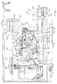
- a keyboard instrument embodying the present invention largely comprises a grand piano 100, an electronic sound generating system and a mode controlling system 300, and selectively enters into an acoustic sound mode for a performance with acoustic tones, a faint sound mode for a performance in a small volume and a silent mode without the acoustic tones.
- the silent mode is broken down into a true silent sub-mode for a fingering in a perfect silence and an electronic sound mode for a performance with synthetic tones, and the synthetic tones are electronically produced by the electronic sound generating system 200.
- the synthetic tones usually have a timbre identical with the acoustic tones, the electronic sound generating system 200 can impart any timbre to the synthetic tones.
- the acoustic piano 100 is of the grand type, and is constructed as similar to an ordinary grand piano. Namely, the acoustic piano 100 comprises a keyboard 110 implemented by eighty-eight black and white keys 110a and 110b, and the black and white keys 110a and 110b are turnably supported by a center rail 111 on a stationary key bed structure 112.
- the acoustic piano 100 further comprises a plurality of key action mechanisms 120 respectively linked with capstan screws 113 of the black and white keys 110a and 110b, and the key action mechanisms 120 are turnably supported by a whippen rail 121.
- the whippen rail 121 in turn is supported by action brackets 122 mounted on respective bracket blocks (not shown) on the key bed structure 112.
- the acoustic piano 100 further comprises hammer assemblies 140 respectively associated with the key action mechanisms 120, and each hammer assembly 140 comprises a hammer shank flange 141 bolted to a shank flange rail 142 which in turn is supported by the action brackets 122, a hammer shank 143 turnable with respect to the hammer shank flange 141, a hammer roller 144 rotatably connected with the hammer shank 143 and a hammer head 145 attached to the leading end portion of the hammer shank 143.
- the top end of the jack 124 passes through the repetition lever 125, and is held in contact with the hammer roller 144 before an escape from the hammer roller 144.
- the acoustic piano 100 further comprises a plurality sets of strings respectively struck by the hammer heads 145, damper mechanisms 160 for damping vibrations on the strings 150 and a pedal mechanism 170 for imparting predetermined effects on the acoustic tones produced through the vibrations of the strings 150.
- Each of the damper mechanisms 160 has a link mechanism 161 engageable with the rear end portion of the associated key 110a or 110b and a damper head 162 engageable with the associated set of strings 150
- the pedal mechanism 170 has a damper pedal 171, a muffler pedal 172, a soft pedal 173 and the associated link sub-mechanisms 174.
- the strings 150 horizontally extends over the hammer assemblies 140, and are anchored at a plate 151 on a pin block 152.
- Reference numeral 153 is indicative of a virtual surface coplanar with the lower surface of the pin block 152.
- the damper mechanisms 160 and the pedal mechanism 170 indirectly relate to the present invention, and no further description is incorporated hereinbelow.
- the capstan button 113 on the depressed key 110a or 110b pushes up the whippen assembly 123, and the rear end portion of the depressed key 110a or 110b spaces the associated damper head 162 from the set of strings 150.
- the whippen assembly 123 and the jack 124 rotates in the counter clockwise direction around the whippen rail 121 without a relative motion therebetween, and the jack 124 pushes the hammer roller 144.
- the hammer shank 143 rotates around the hammer shank flange 141 in the clockwise direction.
- the toe 124a of the jack 124 is brought into contact with the regulating button 126, and starts to turn around the whippen assembly 123 against the repetition spring 128.
- the jack 124 finally escapes from the hammer roller 144, and kicks the hammer assembly 140. Then, the hammer assembly 140 rushes toward the strings 150, and the key action mechanism 120 and the hammer assembly 140 give the unique key-touch to the player at the escape.
- the keyboard instrument embodying the present invention gives the unique key-touch to the player in the acoustic, faint and silent modes.
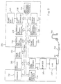
- the electronic sound generating system 200 comprises a plurality of key sensors 210 respectively associated with the black and white keys 110a and 110b for monitoring the keys, a plurality of pedal sensors 220 for monitoring link sub-mechanisms of the peal mechanism 170, a controller 230 for producing an audio signal AD, a headphone 260 for producing the synthetic tones from the audio signal AD and a mode shift switch 270.
- a keyboard instrument according to the present invention may further comprise a plurality of hammer sensors for monitoring the hammer assemblies 140 and/ or a speaker system.
- Each of the pedal sensors 220 also changes a detecting signal DT2 depending upon the position of the associated pedal, and the mode shift switch 270 is manipulated by a player for producing a mode signal MODE indicative of one of the acoustic/faint mode and the silent mode.
- the electronic sound generating system 200 comprises a supervisor 231, a data memory 232 for original vibrations, a data processor 233 for original vibrations, a data memory 234 for resonant vibrations, a data processor 235 for resonant vibrations, a data processor 236 for sound spectrum, a working memory 237, a floppy disk controller 238, a floppy disk driver 239, an audio signal generator 240, an equalizer 241, an amplifier 242 and a bus system 243.
- the mode shift switch 270 supplies the mode signal MODE to the controller 230, and the mode signal MODE is assigned to one of the signal input ports of the controller 230.
- the other signal input ports are assigned the key sensors 210 and the pedal sensors 220.
- the supervisor 231 sequentially scans the signal input ports assigned to the mode control signal MODE, the detecting signals DT1 from the key sensors 210 and the detecting signals DT2 from the pedal sensors 220, and supervises the other components 232 to 240 for producing the audio signal AD.
- Various internal registers are incorporated in the supervisor 231, and one of the internal registers is assigned to a mode flag indicative of the presently designated mode.
- the data memory 232 for original vibrations stores a plurality sets of pcm (Pulse Code Modulation ) data codes indicative of frequency specular of original vibrations on the strings 150, and each set of pcm data codes is corresponding to one of the keys 110a and 110b.
- a plurality groups of pcm data codes form a set of pcm data codes, and are corresponding to frequency specular at different intensities or hammer velocity. In general, if a hammer head 145 strongly strikes the associated strings 150, higher harmonics are emphasized.
- the plurality sets of pcm data codes are produced with a sampler (not shown) through sampling of actual vibrations on the sets of strings 150 at appropriate sampling frequency.
- the set of pcm data codes may be produced by means of the data processor 236 through a real-time manner. Using a group of pcm data codes, original vibrations produced upon depressing a key 110a or 110b are restored, and the supervisor 231 controls the sequential access to a group of pcm data codes stored in the data memory 232.
- the intensity of frequency spectrum is corresponding to the hammer velocity.
- the intensities are variable with the type and model of the acoustic piano 100.
- the data memory 234 for resonant vibrations stores a plurality sets of pcm data codes indicative of resonant vibrations, and the resonant vibrations take place under a manipulation of the damper pedal 171. While a player is stepping on the damper pedal 171, the damper heads 162 are held off, and some of the related strings are resonant with the strings directly struck by the associated hammer head 145.
- the resonant tones range -10 dB and -20 dB with respect to the tone originally produced at the strike with the hammer head 145, and time delay of several millisecond to hundreds millisecond is introduced between the originally produced tone and the resonant tones.
- the resonant tones continues several seconds. However, the player may rapidly terminate the original and resonant tones by releasing the damper pedal 171, and the audio signal generator 240 is responsive to the detecting signal DT2 of the pedal sensors 220 for the rapidly extinguishing the tones.
- the pcm data codes stored in the data memory 234 are indicative of frequency specular of the resonant vibrations, and are also produced by means of the sampler or the data processor 236 for resonant vibrations.
- Each of the plurality sets of pcm data codes for the resonant tones is addressable with the detecting signal DT1 indicative of the depressed key 110a or 110b, and is constituted by six groups of pcm data codes at the maximum.
- Each group of pcm data codes is corresponding to one of the resonant strings 150, and the second harmonic to the sixth harmonic are taken into account for strings one octave higher than low-pitched sounds.
- the depressed key is lower than the thirteenth key with respect to the lowest key, the string one octave lower than the depressed key should be taken into account.
- the data processor 236 for sound spectrum can produce not only a group of pcm data codes indicative of frequency spectrum for original vibrations but also a set of pcm data codes indicative of frequency specular for resonant vibrations as described hereinbefore.
- the data processor 236 is further operative to cause the frequency specular to decay.
- the data processor 236 simulates the decay of the vibrations, and sequentially decreases the values of the pcm data codes.
- the resonant tones continue for several seconds in so far as the player keeps the damper pedal 171 in the depressed state. However, if the player releases the damper pedal 171, the resonant tones are rapidly decayed.
- the data processor 236 also simulates the decay, and sequentially decreases the values of the pcm data codes for the resonant vibrations.
- the decay is not constant. If the player releases the damper pedal 171 through a half pedal, the tones decay at lower speed rather than the ordinary release. Moreover, some players use the half pedal in such a manner as to retard low-pitched tones rather than high-pitched tones, and such a pedal manipulation is called as an oblique contact. On the contrary, if the damper pedal 171 causes all the dampers to be simultaneously brought into contact with the strings 150, the damper manipulation is referred to as simultaneous contact.
- the data processor 236 further simulates the gentle decay for the release through the half pedal as well as the oblique contact, and the values of the pcm data codes are decreased at either high, standard or low speed in the simultaneous contact and at different speed in the oblique contact.
- the data processor 236 may change the ratio between the fundamental tone and the harmonics thereof for the half pedal, and decay high-order harmonics faster than the fundamental tone.
- the frame of an acoustic piano usually vibrates, and the frame noise participates in the piano tone.
- the data processor 236 may take these secondary noise into account and modify the frequency ratio.
- the audio signal generator 240 comprises a digital filter, a digital-to-analog converter and a low-pass filter, and produces the analog audio signal from the pcm data codes supplied from the data memories 232 and 234 and/ or the data processors 233, 235 and 236.
- the pcm data codes are subjected to a digital filtering, and are, then, converted into the analog audio signal AD. If a speaker system is incorporated in the electronic sound producing system 200, the vibration characteristics of the speaker system and a speaker box would be taken into account for the digital filtering. In either case, the pcm data codes are modified in such a manner that the frequency spectrum of produced sounds becomes flat.
- the digital filter is of the FIR type. However, an IIR type digital filter is available. An oversampling type digital filter may follow the digital filtering for eliminating quantized noises.
- the digital-to-analog converter After the digital filtering, the digital-to-analog converter produces the analog audio signal AD, and the analog audio signal AD is filtered by the low-pass filter.
- the low-pass filter is of a Butterworth type for improving group delay.
- the analog audio signal AD thus filtered is supplied through the equalizer 221 to the amplifier unit 242, and the amplifier unit 242 amplifies the analog audio signal AD for driving the headphone 260.
- the supervisor 211 may format the detecting signals D1 of the key sensors 210 and the detecting signals D2 of the pedal sensors 220 in accordance with the MIDI standards, and the MIDI codes are stored in a floppy disk under the control of the floppy disk controller 238. If the keyboard instrument can record and reproduce a performance, the keyboard instrument has five modes of operation, i.e., the acoustic sound mode, the silent mode, the faint mode, the recording mode and the playback mode, and the silent mode also has two sub-modes.
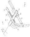
- the mode controlling system 300 is provided in a gap between the hammer assemblies 140 and the plurality sets of strings 150, and largely comprises a stopper mechanism 310 shiftable between a free position closer to the strings 150 and a blocking position spaced from the strings 150 and a driving mechanism 320 slidable along the strings 150 for changing the stopper mechanism 310 between the free position and the blocking position.
- the hammer assemblies 140 return to their home positions shown in Fig. 1, and a gap between the hammer shanks 143 and the strings 150 is increased from the hammer shank flanges 141 toward the leading ends of the hammer shanks 143.
- the driving mechanism 320 slidable along the strings 150 is insertable into the gap from the hammer shank flanges 141 toward the leading ends of the hammer shanks 143, and the stopper mechanism 310 movable in the direction perpendicular to the strings is only locatable in the gap in the vicinity of the leading ends of the hammer shanks 143.
- the driving mechanism 320 has a plurality of first frame members 321 fixed at front end portions 321a thereof to the shank flange rail 142 and the hammer shank flanges 141 and at the rear end portions thereof 321b to a support member 322 on the whippen rail 121.
- the intermediate portions 321c of the first frame members 321 extend between the front end portions 321a and the rear end portions 321b substantially in parallel to the virtual plane 153.
- the driving mechanism 320 further has a pusher 333 shared between all of the second frame members 323, and the pusher 333 has a groove engaged with the turn-back portions 323b.
- a suitable link mechanism is connected with the pusher 333, and a player manipulates the link mechanism so that the pusher 333 slides along the virtual plain 153 and the strings 150.
- the pusher 333 is rigid, and is formed of metal or hard plastic.
- the link mechanism connected with the pusher 333 is further linked with the mode shift switch 270, and the player can shift the keyboard instrument between the modes through the manipulation of the link mechanism.
- the pusher 333 may be driven by an electronic motor associated with a suitable converting mechanism between a rotation and a reciprocal motion or by a solenoid-operated actuator.
- the electric motor and the solenoid-operated actuator may be controlled by the controller 230 in response to the mode signal MODE.
- the stopper mechanism 310 has a plurality of deformable frame members 311 respectively associated with the hammer assemblies 140 and a plurality of cushion members 312 respectively attached to the deformable frame members 311, and the deformable frame members 311 are fixed to the rear end portions 321b of the first frame members 321 such that the cushion members 312 are faced to the hammer shanks 143 of the associated hammer assemblies 140 in the home positions.
- the cushion members 312 are formed of felt, cloth, urethane foam or rubber foam.
- the deformable frame members 311 lift the cushion members 312 in the vicinity of the virtual plane 153, and the cushion members 312 are spaced from the hammer shanks 143.
- the stopper mechanism 310 is staying in the free position, and the hammer heads 145 can strike the associated strings 150 without interruption of the cushion members 312.
- the pusher 333 If the pusher 333 is moved from a home position toward the rear end of the keyboard instrument along the turn-back portions 323b, the pusher 333 is brought into contact with the deformable frame members 311, and deforms the frame members 311 such that the cushion members 312 becomes closer to the hammer shanks 143 in the home positions. If the pusher 333 is further moved toward the rear end of the keyboard instrument, the deformable frame members 311 are further deformed, and the cushion members 312 become much closer to the hammer shanks 143. However, if the pusher 333 returns to the home position, the deformable frame members 311 allows the cushion members 312 to return to the initial positions.
- the stopper mechanism 310 enters into a muffler position, the hammer shanks 143 are brought into contact with the cushion members 312, and the hammer heads 145 softly strike the associated strings 150. In other words, the hammer assemblies 140 concurrently strike the associated cushion members 312 and the associated strings 150. However, when the stopper mechanism 310 enters into the blocking position, the hammer assemblies 140 are brought into contact with the cushion members 312 without strike against the strings 150.
- the mode shift switch 270 supplies the mode signal MODE indicative of the silent mode to the controller 230. If the player inserts the jack of the headphone 260 to the socket 244, the keyboard instrument enters into the electronic sound sub-mode, and the player can hear the synthetic tones through the headphone. However, if the jack is pulled out, the keyboard instrument enters into the true silent sub-mode, and the player can practice the fingering on the keyboard 110 in a perfectly silent ambience.
- the controller 230 communicates with the key sensors 210 and the pedal sensors 220 for producing the audio signal AD.
- the key action mechanisms 120 give the piano key-touch to the player in cooperation with the hammer assemblies 140. However, the strings 150 are blocked from the hammer heads 145 by means of the stopper mechanism 310, and never vibrate for producing an acoustic tone.
- the keyboard instrument enters into the faint mode, and the hammer assemblies 140 can concurrently strike the associated strings 150 and the associated cushion members 312.
- the hammer assemblies 140 give the piano-touch to the player in cooperation with the key action mechanisms 120, and softly strike the associated strings 150 due to the interruption of the stopper mechanism 310.
- the strings 150 faintly vibrate for producing acoustic tones, and the volume is smaller than those in the acoustic mode.
- the player can record the music performed in either acoustic or silent mode in a floppy disk, and can reproduce the music in the playback mode.
- the keyboard instrument gives the piano-touch to the player in both acoustic and electronic sound modes, and allows the player to practice a fingering on the keyboard without an acoustic sounds.
- another keyboard instrument embodying the present invention also largely comprises an acoustic piano 400, an electronic sound generating system 430 and a mode controlling system 450, and selectively enters into the acoustic mode, the silent mode and the faint mode as similar to the first embodiment.
- the silent mode has the two sub-modes, i.e., the true silent sub-mode and the electronic sound sub-mode, and the recording mode and the playback mode may be further selectively established in the keyboard instrument implementing the second embodiment.
- the acoustic piano 400 and the electronic sound generating system 430 are similar to those of the first embodiment, and, for this reason, the component members and mechanisms thereof are labeled with the same references as those of the first embodiment without detailed description.
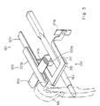
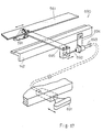
- the mode controlling system also largely comprises a stopper mechanism 460 and a driving mechanism 470, and the driving mechanism 470 is constructed by the first and second frame members 321 and 322 and link members 471 and 472.
- the pusher 333 is deleted from the driving mechanism 470, and is replaced with a slider 461 forming a part of the stopper mechanism 460.
- the stopper mechanism 460 comprises the slider 461 and a plurality of cushion members 462, and the link member 472 is connected with the slider 461.
- the link mechanism 472 and the slider 461 slide along the virtual plane 153, and the second frame member 322 guides the slider 461.
- the cushio members 462 is formed of felt, cloth, urethane foam or rubber foam.
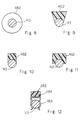
- the slider 461 While the slider 461 is staying a rearmost position, the slider 461 is faced to the cushon members 462 as shown in Fig. 7, and the cushio members 462 are brought into contact with the slider 462 after the escape of the jacks 124 from the hammer rollers 144.
- the hammer assemblies 140 rebound on the slider 461, and the hammer heads 145 do not strike the associated stirngs 150.
- the stopper mechanism 460 enters into the blocking position.
- the slider 461 is moved from the rearmost position toward the frond end of the keyboard instrument, the slider 461 directly faces the hammer shanks 143 as shown in Fig. 5, and the hammer assemblies can strike the assoicated strings 150 without an interruption of the slider 461. If the slider 461 is directly faced to the hammer shanks 143, the stopper mechanism 460 is in the free position.
- the cushion members 462 are tubular as shown in Fig. 8. However, the cushion members may have any cross section illustrated in Figs. 9 to 11. Moreover, each of the cushion members 462 is replaceable with a cushion member 482 implemented by a snap member 483 atatched to a cushion layer 484, and is avialable for remodeling an acoustic piano.
- the keyboard instrument can further has a fain mode where the hammer assemblies 140 concurrently strike the spacer 461 and the strings 150.
- the keyboard instrument implementing the second embodiemnt behaves in the acoustic mode and the silent mode as similar to the first embodiemnt, and, for this reason, description on these modes is omitted for avoiding repetition.
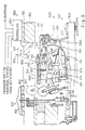
- yet another keyboard instrument embodying the present inention also largely comprises a grand piano 500, an electronic sound generating system 520 and a mode controlling system 550, and selectively enters into the acoustic sound mode, and the silent mode.
- the keyboard instrument may further enter into the recording mode and the playback mode.
- the grand piano 500 and the electronic sound generating system 520 are similar to those of the first embodiment, and component members and mechanisms of the grand piano 500 and components of the electronic sound generating system 520 are labeled with the references designating the corresponding members, mechanisms and components without detailed description.
- the grand piano 500 similarly behaves as a grand piano.
- the hammer heads 145 reach escaping points 10 millimeters spaced from the associated strings 150 in both acoustic sound and silent modes, the jacks 124 escape from the hammer assemblies 140, and the key action mechanisms 120 and the hammer assemblies 140 give the piano-touch to a player at all times.
- the distance d between the toes and the regulating buttons 126 changes the escaping points, and an actuator may move the regulating button 126 depending upon the mode of operation.
- the present inventor proposed a mechanism for changing the escaping point in Japanese Patent Application No. 5-200581. If the regulating buttons 126 are accompanied with the mechanism, the jacks 124 escape from the hammer assemblies 140 at 2 to 3 millimeters spaced from the strings 150 in the acoustic sound mode and at 10 millimeters spaced from the strings 150 in the silent mode.
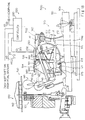
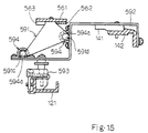
- the mode controlling system 550 largely comprises a stopper mechanism 560 and a driving mechanism 590, and the driving mechanism 590 changes the stopper mechanism 560 between the free position and the blocking position.
- the stopper mechanism 560 is located in the vicinity of the hammer heads 145, and the driving mechanism 590 is closer to the hammer shank flanges 141.
- the mode shift switch 270 may be linked with the driving mechanism 590.
- the stopper mechanism 560 comprises a base plate member 561 extending over the keyboard 110 and shared between all of the eighty-eight keys 110a and 110b, a reinforcing plate member 562 attached to the lower surface of the base plate member 561 on the front side, and a plurality of cushion members 563 respectively corresponding to the hammer heads 145 and attached to the lower surface of the base plate member 561 at intervals.
- the interval between adjacent two of the cushion members 563 is equal to the distance between the associated hammer heads 145, and is about 13 millimeters in this instance.
- the distance between the adjacent two hammer heads 145 is hereinbelow referred to as "pitch".
- the driving mechanism 590 comprises five bracket members 591 bolted to both end portions and three intermediate portions of the base plate member 561, because the eighty-eight action mechanisms 120 are divided into four groups corresponding to four spaces defined by the piano frames.
- Each of the bracket-members 591 has two arm members 591a and 591b spaced apart from each other, and a pair of shafts 591c and 591d interconnects the arm members 591a an 591b such that a gap takes place therebetween.
- the driving mechanism 590 further comprises supporting bracket members 592 bolted to the hammer shank rail 142 and to the whippen rail 121 through regulating units 593, and bearing units 594 fixed to the supporting bracket members 592.
- each of the supporting bracket member 592 has a step where the bearing units 594 are bolted.
- the height of each regulating unit 121 is regulable, and appropriately interconnects the whippen rail 121 and the supporting bracket 592.
- a pair of bearing units 594 is associated with each bracket member 591, and has cloth members 594a slidably supporting the shaft members 591c and 591d.
- the driving mechanism 590 further comprises a nob 595 supported through a stationary bracket member 596 by the key bed structure 112, a flexible wire 597 movable in a tube member 598 fixed to a bracket member 599, an bar member 600 fixed at one end thereof to the leading end of the flexible wire 597, a rod member 601 fixed to the other end of the bar member 600 and turnably supported by the shank flange rail 142 through a bracket 602 and a pusher 603 fixed to the leading end of the rod member 601.
- the pusher 603 is loosely inserted into the gap defined in one of the bracket members 591, and is turnable together with the rod member 601 for moving the base plate member 561 in the perpendicular direction of the strings 150.
- the nob 595 has two stable points in the stationary block member 112, and the distance between the two stable points is corresponding to the half pitch.
- two stoppers attached to the base plate member 561 or the shaft members 591c and 591d may restrict the sliding motion of the base plate member 561.
- a plurality of hammer sensors 290 are respectively fixed to the supporting bracket members 592, and are operative to monitor the hammer assemblies 140 instead of the key sensors.
- Each of the hammer sensors 290 is implemented by a shutter plate 291 attached to the associated hammer shank 143 and a photocoupler 292, and produces the detecting signal DT1 indicative of the motion of the hammer assembly 140.
- the hammer shanks 143 are faced to the base plate member 561 between the cushion members 563, and the distance between the stopper mechanism 560 and each hammer shank 143 is increased through the sliding motion of the base plate member 561.
- the stopper mechanism 560 is spaced from the hammer shanks 143 in the respective home positions, and enters into the free position.
- the mode shift switch supplies the mode signal MODE indicative of the acoustic sound mode to the controller 230, and the controller 230 does not produce the audio signal AD.
- the depressed keys 110a and 110b cause the associated key action mechanisms 120 to rotate the hammer assemblies 140 in the clockwise direction in Fig. 13, and the key action mechanisms 120 and the hammer assemblies 140 give the piano key-touch to the player at the escapes of the jacks 124.
- the hammer assemblies 140 strikes the strings 150 without an interruption of the cushion members 563, and rebound on the strings 150.
- the strings 150 vibrate for producing acoustic tones.
- the flexible wire 597 rotates the bar member 600 in the counter clockwise direction in Fig. 14, and the pusher 603 pushes the bracket 591 toward the left side.
- the base plate member 561 slides toward the left side by a half pitch, and the cushion members 563 interposed between the hammer shanks 143 and the sets of strings 150 as shown in Fig. 16.
- the distance from each hammer shank 143 in the home position is decreased, and the stopper mechanism 560 enters into the blocking position.
- the mode shift switch 270 supplies the mode signal MODE indicative of the silent mode to the controller 230, and the controller 230 becomes ready for a electronic synthesis of the tones.
- the jacks 124 escape from the hammer assemblies 140, and rotate the hammer assemblies 140 toward the strings 150.
- the player feels the piano key-touch.
- the keyboard instrument embodying the present invention is changed between the acoustic mode and the silent mode through the sliding motion of the driving mechanism 590, and gives the piano key-touch to the player in both acoustic sound and silent modes.
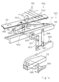
- Fig. 17 shows another driving mechanism 690 replaceable with the driving mechanism 590, and comprises a nob 691, a flexible wire 692 slidable in a tube member 693, a bracket member 702 connected between the shank flange rail 142 and the tube member 693, a plate member 695 connected between the flexible wire 692 and the base plate member 561.
- a guide member is associated with the plate member 695, and allows the plate member 695 to slide by a half pitch together with the base plate member 451.
- the nob 691 is manipulated by a player, and the driving mechanism 690 laterally moves the base plate member 561 for changing the stopper mechanism between the free position and the blocking position.
- the nob 595/691 and the flexible wire 597/692 are replaceable with a solenoid operated actuator or a combination of a motor unit and a suitable mechanism such as a chain and sprockets. Moreover, the nob and the flexible wire may be replaced with a pedal and a link mechanism, and the bracket members 591 may be driven by respective pushers 603 or the respective plate members 695.
Landscapes
- Physics & Mathematics (AREA)
- Engineering & Computer Science (AREA)
- Acoustics & Sound (AREA)
- Multimedia (AREA)
- Electrophonic Musical Instruments (AREA)
Claims (5)
- Ein Tasteninstrument, das zumindest einen akustischen Geräusch- bzw. Tonmodus zum Erzeugen von akustischen Geräuschen bzw. Tönen hat und einen elektronischen Geräusch- bzw. Tonmodus zum Erzeugen von synthetischen Geräuschen bzw. Tönen, das folgendes aufweist:dadurch gekennzeichnet, daßa) ein akustisches Klavier (100; 400; 500), das folgendes umfaßta-1) eine Tastatur (110), die durch eine Vielzahl von schwingbaren Tasten (110a/110b) dargestellt wird, die von einem Spieler in sowohl dem akustischen Tonmodus als auch dem elektronischen Tonmodus gedrückt werden, wobei Noten einer Tonleiter der Vielzahl von schwingbaren Tasten zugeordnet sind,a-2) eine Vielzahl von Tastenbetätigungsmechanismen (120), die entsprechend mit der Vielzahl von schwingbaren Tasten verbunden sind und selektiv durch die gedrückten Tasten der Tastatur in sowohl dem akustischen Tonmodus als auch in dem elektronischen Tonmodus betätigt werden,a-3) eine Vielzahl von Hammeranordnungen (140), die entsprechend der Vielzahl von Tastenbetätigungsmechanismen zugeordnet sind und selektiv bei einer Drehung von betätigten Tastenbetätigungsmechanismen angetrieben werden, die mit den gedrückten Tasten in sowohl dem akustischen Tonmodus als auch dem elektronischen Tonmodus verbunden sind, wobei die betätigten Tastenbetätigungsmechanismen und die zugeordneten Hammeranordnungen einen Klavieranschlag in sowohl dem akustischen Tonmodus als auch in dem elektronischen Tonmodus erzeugen, unda-4) eine Vielzahl von Saitenmitteln (150), die entsprechend der Vielzahl von Hammeranordnungen zugeordnet sind, und die selektiv von Hammeranordnungen angeschlagen werden, die von den betätigten Tastenbetätigungsmechanismen in dem akustischen Tonmodus angetrieben werden, um akustische Töne zu erzeugen, wobei ein Spalt zwischen jeder Hammeranordnung und den zugeordneten Saitenmitteln gelegen ist, wobei der Spalt an der Lage eines Hammerkopfes jeder Hammeranordnung größer als an der Lage der Drehachse jeder Hammeranordnung ist;b) ein elektronisches Tonerzeugungssystem (200; 430; 520), das in dem elektronischen Tonmodus in die Lage versetzt wird, synthetische Töne zu erzeugen, die Noten haben, die von den gedrückten Tasten identifiziert werden; undc) ein Modussteuerungssystem (300; 450; 550), das folgendes umfaßtc-1) Stoppermittel (310; 460; 560), die in dem Spalt vorgesehen sind und zumindest zwischen einer freien Position in dem akustischen Tonmodus und einer Blockierposition in dem elektronischen Tonmodus bewegbar sind, wobei die Blockierposition näher an der Vielzahl von Hammeranordnungen in den Heimat- bzw. Ausgangspositionen ist, undc-2) Antriebsmittel (320; 470; 590; 690), die den Stoppermitteln zugeordnet sind und entlang der Vielzahl von Saitenmitteln bewegbar sind, um die Stoppermittel zwischen der freien Position und der Blockierposition zu verändern, wobei die Hammeranordnungen die Saitenmittel ohne eine Unterbrechung der Stoppermittel in der freien Position anschlagen, wobei die Hammeranordnungen in Kontakt mit den Stoppermitteln in der Blockierposition gebracht werden, ohne einen Anschlag gegen die Saitenmittel,
das Modussteuerungssystem (300; 450; 550) ein längsförmiges gleitbares Glied (333; 461; 561) umfaßt, das sich im wesentlichen quer zu der Vielzahl von Saitenmitteln erstreckt und in einer Ebene parallel zu der Vielzahl von Saitenmittel gleitbar ist, um die Stoppermittel zwischen der freien Position und der Blockierposition zu verändern. - Das Tasteninstrument nach Anspruch 1, bei dem die Antriebsmittel (320; 470; 590; 690) näher an den Achsen der Vielzahl von Hammeranordnungen sind als der Stoppermechanismus.
- Das Tasteninstrument nach Anspruch 2, bei dem das akustische Klavier (100) ein Flügel ist,
wobei die Antriebsmittel (320) folgendes aufweisenFührungsmittel (321/323), die einen Gleitpfad entlang der Vielzahl von Saitenmitteln (150) vorsehen und die von Aktionsklammermitteln (122) getragen sind, die die Vielzahl von Tastenaktionsmechanismen und die Vielzahl von Hammeranordnungen tragen, undeinen Drücker (33), der entlang des Gleitpfads gleitbar ist, wobei die Stoppermittel (310) folgendes aufweisenverformbare Rahmenmittel (311), die von den Führungsmitteln (321/323) getragen sind und von dem Drücker (333) elastisch verformt werden, und Kissen- bzw. Dämpfmittel (312), die von den verformbaren Rahmenmitteln (311) getragen sind und Hammerschenkeln (143) der Vielzahl von Hammeranordnungen (140) zugewendet sind, wobei das Dämpfungsglied (312) näher an die Hammerschenkel (143) kommt, um es den Stoppermitteln (310) zu erlauben, in die Blockierposition einzutreten, wenn der Drücker (333) die verformbaren Rahmenmittel (311) elastisch verformt, wobei die Dämpfungsmittel (312) von den Hammerschenkeln (143) beabstandet sind, aufgrund einer elastischen Kraft der verformbaren Rahmenmittel (311), um zu bewirken, daß die Stoppermittel (310) in die freie Position eintreten, wenn der Drücker (333) von den verformbaren Rahmenmitteln verlassen wird. - Das Tasteninstrument nach Anspruch 2, bei dem das akustische Klavier (400) ein Flügel ist,
wobei die Antriebsmittel (470) folgendes aufweisenwobei die Stoppermittel (470) folgendes aufweisenFührungsmittel (321/323), die einen Gleitpfad entlang der Vielzahl von Saitenmitteln (150) vorsehen und von den Aktionsklammermitteln (122) getragen sind, die die Vielzahl von Tastenaktionsmechanismen (120) unddie Vielzahl von Hammeranordnungen (140) tragen, undBetätigermittel (471/472), die angetrieben bzw. mit Energie versorgt werden, wenn das Tasteninstrument zwischen dem akustischen Tonmodus und dem elektronischen Tonmodus geändert wird,Gleitmittel (461), die von den Betätigermitteln betätigt werden, um den Gleitpfad entlang zu gleiten, undeine Vielzahl von Dämpfungsgliedern (462), die entsprechend von Hammerschenkeln (143) der Vielzahl von Hammeranordnungen (140) getragen sind, wobei die Gleitmittel (461) bewegt werden, um der Vielzahl von Dämpfungsgliedern (462) zugewandt zu sein, um es den Stoppermitteln (470) zu ermöglichen, in die Blockierposition einzutreten, wobei die Gleitmittel aus den Orbiten bzw. Umlaufbahnen der Vielzahl von Dämpfungsgliedern bewegt werden, um zu bewirken, daß die Stoppermittel in die freie Position eintreten. - Das Tasteninstrument nach Anspruch 2, bei dem das akustische Klavier (500) ein Flügel ist,
wobei die Stoppermittel (560) folgendes aufweisenPlattenmittel (561), die zwischen der Vielzahl von Hammeranordnungen (140) und der Vielzahl von Saitenmitteln (150) vorgesehen sind, in einer gleitbaren Weise in eine senkrechte Richtung der Vielzahl von Saitenmitteln (150), und die von Aktionsklammermitteln (122) getragen sind, die die Vielzahl von Tastenaktionsmechanismen (120) und die Vielzahl von Hammeranordnungen (140) tragen, undeine Vielzahl von Dämpfungsgliedern (563), die an einer unteren Oberfläche der Plattenmittel in Intervallen bzw. Abständen befestigt sind, die jedes ungefähr gleich einer Tonhöhe der Vielzahl von Hammeranordnungen (140) in der senkrechten Richtung sind,wobei der Antriebsmechanismus bewirkt, daß die Plattenmittel um die Hälfte der Tonhöhe gleiten, so daß die Vielzahl von Hammeranordnungen (140) dem Plattenglied (563) zwischen der Vielzahl von Dämpfungsgliedern (563) in dem akustischen Tonmodus und der Vielzahl von Dämpfungsgliedern (563) in dem elektronischen Tonmodus zugewandt sind.
Applications Claiming Priority (6)
| Application Number | Priority Date | Filing Date | Title |
|---|---|---|---|
| JP6214393 | 1993-03-22 | ||
| JP6214393 | 1993-03-22 | ||
| JP62143/93 | 1993-03-22 | ||
| JP323434/93 | 1993-11-30 | ||
| JP32343493 | 1993-11-30 | ||
| JP5323434A JPH07152365A (ja) | 1993-11-30 | 1993-11-30 | 鍵盤楽器 |
Publications (3)
| Publication Number | Publication Date |
|---|---|
| EP0617403A2 EP0617403A2 (de) | 1994-09-28 |
| EP0617403A3 EP0617403A3 (de) | 1997-12-10 |
| EP0617403B1 true EP0617403B1 (de) | 2001-08-29 |
Family
ID=26403202
Family Applications (1)
| Application Number | Title | Priority Date | Filing Date |
|---|---|---|---|
| EP94104524A Expired - Lifetime EP0617403B1 (de) | 1993-03-22 | 1994-03-22 | Tastaturinstrument mit Selektion einer akustischen oder stillen Wirkungsweise durch einen gleitend bewegenden Stellarm |
Country Status (3)
| Country | Link |
|---|---|
| US (1) | US5434349A (de) |
| EP (1) | EP0617403B1 (de) |
| DE (1) | DE69428069T2 (de) |
Families Citing this family (11)
| Publication number | Priority date | Publication date | Assignee | Title |
|---|---|---|---|---|
| US6011214A (en) * | 1993-11-30 | 2000-01-04 | Yamaha Corporation | Keyboard instruments having hammer stopper outwardly extending from hammer shank and method of remodeling piano into the keyboard instrument |
| JP3438308B2 (ja) * | 1994-03-31 | 2003-08-18 | ヤマハ株式会社 | 鍵盤楽器 |
| JP3336742B2 (ja) * | 1994-05-18 | 2002-10-21 | ヤマハ株式会社 | 鍵盤楽器 |
| US5542328A (en) * | 1995-03-07 | 1996-08-06 | Pimentel; Robert L. | Piano hammer rail stop assembly |
| JP3873522B2 (ja) * | 1999-05-06 | 2007-01-24 | ヤマハ株式会社 | 鍵盤楽器の消音装置 |
| WO2009017961A1 (en) * | 2007-07-31 | 2009-02-05 | Steinway Musical Instruments, Inc. | Pianos playable in acoustic and silent modes |
| JP5298534B2 (ja) * | 2008-01-08 | 2013-09-25 | ヤマハ株式会社 | アクション機構 |
| US7825312B2 (en) * | 2008-02-27 | 2010-11-02 | Steinway Musical Instruments, Inc. | Pianos playable in acoustic and silent modes |
| US8148620B2 (en) * | 2009-04-24 | 2012-04-03 | Steinway Musical Instruments, Inc. | Hammer stoppers and use thereof in pianos playable in acoustic and silent modes |
| US8541673B2 (en) * | 2009-04-24 | 2013-09-24 | Steinway Musical Instruments, Inc. | Hammer stoppers for pianos having acoustic and silent modes |
| DE102019000364B3 (de) * | 2019-01-18 | 2019-08-22 | Hohner Musikinstrumente Gmbh | Handharmonika |
Family Cites Families (20)
| Publication number | Priority date | Publication date | Assignee | Title |
|---|---|---|---|---|
| US533661A (en) * | 1895-02-05 | mcchesney | ||
| DE44782C (de) * | J. P. DEVIGNEE, Professor der Musik in Verviers, Belgien; [ | Vorrichtung zum Verändern der Stärke des Hammeranschlages bei Pianino's | ||
| DE97885C (de) * | ||||
| US537533A (en) * | 1895-04-16 | Electric switch | ||
| US2250065A (en) * | 1940-12-07 | 1941-07-22 | James A Kochl | Musical instrument |
| JPS5167732A (ja) * | 1974-12-05 | 1976-06-11 | Dainippon Jochugiku Kk | Kukaneazoorusatsuchuzai |
| JPS5555880A (en) * | 1978-10-18 | 1980-04-24 | Canon Inc | Thermal printer |
| DE3516585A1 (de) * | 1984-05-15 | 1985-11-28 | Nippon Gakki Seizo K.K., Hamamatsu, Shizuoka | Daempfungsmechanismus fuer ein klavier |
| JPS61289393A (ja) * | 1985-06-17 | 1986-12-19 | ヤマハ株式会社 | 鍵盤楽器 |
| JPS6232308A (ja) * | 1985-08-03 | 1987-02-12 | Fuji Photo Film Co Ltd | 位置検出装置 |
| EP0239917A3 (de) * | 1986-03-29 | 1989-03-29 | Yamaha Corporation | Automatisches Gerät zum Spielen eines Schallinstrumentes mit akustischen und elektronischen Schallquellen |
| JPS6397997A (ja) * | 1986-10-15 | 1988-04-28 | ヤマハ株式会社 | ピアノの弱音装置 |
| DE3641813C1 (de) * | 1986-12-06 | 1988-04-14 | Reinhard Franz | Tastatur fuer eine elektronische Orgel |
| DE3707591C1 (en) * | 1987-03-10 | 1988-05-26 | Seiler Ed Pianofortefab Gmbh | Grand piano or piano |
| US5115705A (en) * | 1989-02-16 | 1992-05-26 | Charles Monte | Modular electronic keyboard with improved signal generation |
| JPH02119693U (de) * | 1989-03-13 | 1990-09-26 | ||
| US5001339A (en) * | 1989-03-27 | 1991-03-19 | Gulbransen, Inc. | Opto-electronic sensing method and device for an acoustic piano |
| IT1244634B (it) * | 1991-02-08 | 1994-08-08 | Nat Starch & Chemical S P A | Composizione indurente per colle urea-formaldeide, procedimento per lasua produzione e kit che la comprende. |
| US5247129A (en) * | 1991-06-10 | 1993-09-21 | Yamaha Corporation | Stringless piano-touch electric sound producer for directly driving a sound board on the basis of key actions |
| US5374775A (en) * | 1992-06-09 | 1994-12-20 | Yamaha Corporation | Keyboard instrument for selectively producing mechanical sounds and synthetic sounds without any mechanical vibrations on music wires |
-
1994
- 1994-03-21 US US08/215,295 patent/US5434349A/en not_active Expired - Fee Related
- 1994-03-22 DE DE69428069T patent/DE69428069T2/de not_active Expired - Fee Related
- 1994-03-22 EP EP94104524A patent/EP0617403B1/de not_active Expired - Lifetime
Also Published As
| Publication number | Publication date |
|---|---|
| DE69428069D1 (de) | 2001-10-04 |
| EP0617403A2 (de) | 1994-09-28 |
| DE69428069T2 (de) | 2002-05-02 |
| US5434349A (en) | 1995-07-18 |
| EP0617403A3 (de) | 1997-12-10 |
Similar Documents
| Publication | Publication Date | Title |
|---|---|---|
| EP0573963B1 (de) | Tastaturinstrument zur selektiven Erzeugung von mechanischem Schall und synthetischem Schall ohne mechanische Vibrationen von Saiten | |
| US5428186A (en) | Keyboard instrument selectively entering into acoustic sound mode and silent mode through angular motion of key bed structure | |
| US5602351A (en) | Grand piano-like keyboard instrument for selectively producing acoustic sound and synthesized sound | |
| US5565636A (en) | Keyboard musical instrument equipped with driving unit for hammer stopper located in wide space in front of hammer assemblies | |
| KR0136946B1 (ko) | 잭과 조절 버튼 사이에서 가변 접촉점을 가지는 키이보드 악기 | |
| JPH0659667A (ja) | 鍵盤楽器 | |
| EP0617403B1 (de) | Tastaturinstrument mit Selektion einer akustischen oder stillen Wirkungsweise durch einen gleitend bewegenden Stellarm | |
| EP0627723B1 (de) | Tasteninstrument mit Fänger für stilles Spiel auf Tastatur | |
| US5444181A (en) | Keyboard instrument selectively entering into an acoustic sound mode and an electronic sound mode through a rotation of a stopper with a cushion sheet against damper wires | |
| US5608175A (en) | Keyboard musical instrument having regulable regulating buttons linked with hammer stopper | |
| US5483861A (en) | Keyboard instrument equipped with durable hammer stopper for selectively producing acoustic sounds and synthesized sounds | |
| US5594188A (en) | Keyboard musical instrument having key action mechanisms movable to and from strings | |
| JP3569660B2 (ja) | 鍵盤楽器用音源 | |
| JPH07271354A (ja) | アコースティック楽器の自動演奏システム | |
| JP3448948B2 (ja) | 鍵盤楽器およびその消音装置 | |
| JP3832500B2 (ja) | 鍵盤楽器 | |
| JPH0887269A (ja) | 鍵盤楽器 | |
| KR0155260B1 (ko) | 피아노선의 기계적 진동 없이 기계음 모드와 합성음 모드를 선택적으로 시작하는 건반악기 | |
| JP3412288B2 (ja) | 耐久性を有するハンマストッパを有し、アコースティック音と電子音とを選択的に生成する鍵盤楽器 |
Legal Events
| Date | Code | Title | Description |
|---|---|---|---|
| PUAI | Public reference made under article 153(3) epc to a published international application that has entered the european phase |
Free format text: ORIGINAL CODE: 0009012 |
|
| 17P | Request for examination filed |
Effective date: 19940322 |
|
| AK | Designated contracting states |
Kind code of ref document: A2 Designated state(s): DE FR IT |
|
| PUAL | Search report despatched |
Free format text: ORIGINAL CODE: 0009013 |
|
| AK | Designated contracting states |
Kind code of ref document: A3 Designated state(s): DE FR IT |
|
| 17Q | First examination report despatched |
Effective date: 19990906 |
|
| GRAG | Despatch of communication of intention to grant |
Free format text: ORIGINAL CODE: EPIDOS AGRA |
|
| GRAG | Despatch of communication of intention to grant |
Free format text: ORIGINAL CODE: EPIDOS AGRA |
|
| GRAH | Despatch of communication of intention to grant a patent |
Free format text: ORIGINAL CODE: EPIDOS IGRA |
|
| GRAH | Despatch of communication of intention to grant a patent |
Free format text: ORIGINAL CODE: EPIDOS IGRA |
|
| GRAA | (expected) grant |
Free format text: ORIGINAL CODE: 0009210 |
|
| AK | Designated contracting states |
Kind code of ref document: B1 Designated state(s): DE FR IT |
|
| PG25 | Lapsed in a contracting state [announced via postgrant information from national office to epo] |
Ref country code: IT Free format text: LAPSE BECAUSE OF FAILURE TO SUBMIT A TRANSLATION OF THE DESCRIPTION OR TO PAY THE FEE WITHIN THE PRE;WARNING: LAPSES OF ITALIAN PATENTS WITH EFFECTIVE DATE BEFORE 2007 MAY HAVE OCCURRED AT ANY TIME BEFORE 2007. THE CORRECT EFFECTIVE DATE MAY BE DIFFERENT FROM THE ONE RECORDED.SCRIBED TIME-LIMIT Effective date: 20010829 |
|
| REF | Corresponds to: |
Ref document number: 69428069 Country of ref document: DE Date of ref document: 20011004 |
|
| EN | Fr: translation not filed | ||
| PGFP | Annual fee paid to national office [announced via postgrant information from national office to epo] |
Ref country code: DE Payment date: 20020404 Year of fee payment: 9 |
|
| PLBE | No opposition filed within time limit |
Free format text: ORIGINAL CODE: 0009261 |
|
| STAA | Information on the status of an ep patent application or granted ep patent |
Free format text: STATUS: NO OPPOSITION FILED WITHIN TIME LIMIT |
|
| 26N | No opposition filed | ||
| PG25 | Lapsed in a contracting state [announced via postgrant information from national office to epo] |
Ref country code: DE Free format text: LAPSE BECAUSE OF NON-PAYMENT OF DUE FEES Effective date: 20031001 |
|
| ET | Fr: translation filed | ||
| REG | Reference to a national code |
Ref country code: FR Ref legal event code: ERR Free format text: BOPI DE PUBLICATION N: 02/04 PAGES: 241 PARTIE DU BULLETIN CONCERNEE: BREVETS EUROPEENS DONT LA TRADUCTION N'A PAS ETE REMISE A I'INPI IL Y A LIEU DE SUPPRIMER: LA MENTION DE LA NON REMISE. LA REMISE DE LA TRADUCTION EST PUBLIEE DANS LE PRESENT BOPI. |
|
| REG | Reference to a national code |
Ref country code: FR Ref legal event code: ST Effective date: 20080229 |
|
| PG25 | Lapsed in a contracting state [announced via postgrant information from national office to epo] |
Ref country code: FR Free format text: LAPSE BECAUSE OF NON-PAYMENT OF DUE FEES Effective date: 20020331 |