EP0617517A2 - Modulations-, und Demodulationsverfahren und Vorrichtung - Google Patents
Modulations-, und Demodulationsverfahren und Vorrichtung Download PDFInfo
- Publication number
- EP0617517A2 EP0617517A2 EP94104213A EP94104213A EP0617517A2 EP 0617517 A2 EP0617517 A2 EP 0617517A2 EP 94104213 A EP94104213 A EP 94104213A EP 94104213 A EP94104213 A EP 94104213A EP 0617517 A2 EP0617517 A2 EP 0617517A2
- Authority
- EP
- European Patent Office
- Prior art keywords
- bits
- data
- code
- length
- binding
- Prior art date
- Legal status (The legal status is an assumption and is not a legal conclusion. Google has not performed a legal analysis and makes no representation as to the accuracy of the status listed.)
- Granted
Links
Images


Classifications
-
- G—PHYSICS
- G06—COMPUTING OR CALCULATING; COUNTING
- G06F—ELECTRIC DIGITAL DATA PROCESSING
- G06F3/00—Input arrangements for transferring data to be processed into a form capable of being handled by the computer; Output arrangements for transferring data from processing unit to output unit, e.g. interface arrangements
- G06F3/06—Digital input from, or digital output to, record carriers, e.g. RAID, emulated record carriers or networked record carriers
-
- G—PHYSICS
- G11—INFORMATION STORAGE
- G11B—INFORMATION STORAGE BASED ON RELATIVE MOVEMENT BETWEEN RECORD CARRIER AND TRANSDUCER
- G11B20/00—Signal processing not specific to the method of recording or reproducing; Circuits therefor
- G11B20/10—Digital recording or reproducing
- G11B20/14—Digital recording or reproducing using self-clocking codes
- G11B20/1403—Digital recording or reproducing using self-clocking codes characterised by the use of two levels
- G11B20/1423—Code representation depending on subsequent bits, e.g. delay modulation, double density code, Miller code
- G11B20/1426—Code representation depending on subsequent bits, e.g. delay modulation, double density code, Miller code conversion to or from block codes or representations thereof
-
- H—ELECTRICITY
- H03—ELECTRONIC CIRCUITRY
- H03M—CODING; DECODING; CODE CONVERSION IN GENERAL
- H03M5/00—Conversion of the form of the representation of individual digits
- H03M5/02—Conversion to or from representation by pulses
- H03M5/04—Conversion to or from representation by pulses the pulses having two levels
- H03M5/14—Code representation, e.g. transition, for a given bit cell depending on the information in one or more adjacent bit cells, e.g. delay modulation code, double density code
- H03M5/145—Conversion to or from block codes or representations thereof
-
- H—ELECTRICITY
- H04—ELECTRIC COMMUNICATION TECHNIQUE
- H04N—PICTORIAL COMMUNICATION, e.g. TELEVISION
- H04N5/00—Details of television systems
- H04N5/76—Television signal recording
- H04N5/91—Television signal processing therefor
- H04N5/92—Transformation of the television signal for recording, e.g. modulation, frequency changing; Inverse transformation for playback
- H04N5/926—Transformation of the television signal for recording, e.g. modulation, frequency changing; Inverse transformation for playback by pulse code modulation
- H04N5/9261—Transformation of the television signal for recording, e.g. modulation, frequency changing; Inverse transformation for playback by pulse code modulation involving data reduction
-
- H—ELECTRICITY
- H04—ELECTRIC COMMUNICATION TECHNIQUE
- H04N—PICTORIAL COMMUNICATION, e.g. TELEVISION
- H04N5/00—Details of television systems
- H04N5/76—Television signal recording
- H04N5/91—Television signal processing therefor
- H04N5/93—Regeneration of the television signal or of selected parts thereof
- H04N5/94—Signal drop-out compensation
- H04N5/945—Signal drop-out compensation for signals recorded by pulse code modulation
Definitions
- This invention relates to a modulating method, a demodulating method, a modulating apparatus, and a demodulating apparatus, and more particularly to a modulating method and a modulating apparatus for modulating data so that it is suitable for data transmission, or recording onto a recording medium, and a demodulating method and a demodulating apparatus for demodulating a modulation code obtained by modulation to reproduce data.
- block coding In transmitting data, or recording data onto a recording medium, e.g., a magnetic disc or an optical disc, etc., modulation of data is carried out so that it is suitable for transmission or recording.
- a data train is divided into blocks in units of m ⁇ i bits (hereinafter referred to as data word) to convert them into code words comprised of n ⁇ i bits in accordance with a suitable code rule.
- i 1
- block code is a fixed length code.
- i max r which is the maximum i
- block code is a variable length code.
- a code which has undergone block coding is called a variable length code (d, k; m, n; r).
- i is called a binding length
- binding length i max is r (hereinafter referred to as the maximum binding length r).
- d indicates the minimum continuous numbers of the same symbols, i.e., so called minimum run of, e.g., 0, and k indicates the maximum continuous numbers of the same symbols, i.e., the maximum run of, e.g., 0.
- variable length code obtained as described above onto, e.g., an optical disc, etc.
- the variable length code is further subjected to so called NRZI (Non Return to Zero Inverted) modulation to carry out recording on the basis of the NRZI modulated variable length code (hereinafter referred to as a recording waveform train).
- EFM Eight to Fourteen Modulation
- This EFM corresponds to code (2, 10; 8, 17; 1).
- the bit interval of a data train is T
- an object of this invention is to provide a modulating method, a demodulating method, a modulating apparatus, and a demodulating apparatus which permit conversion table for modulating, or reverse conversion table for demodulation to be smaller than that of the conventional system, thus making it possible to cause the circuit scale to become more compact than that of the conventional system.
- this application is an improved invention of U.S. Patent Application S.N. 08/029, 133 by the same applicant.
- n ⁇ i bits from the lest significant bit may be taken out as specific bits based on the binding length i from the code obtained at the modulating step.
- this step includes data converting sub-step of converting a portion of the data so that it is in correspondence with a data portion of the conversion table.
- variable length code (d, k; m, n; r) is such that the minimum run d of 0 is four or more.
- variable length code (d, k; m, n; r) is such that the maximum run k of 0 is 22 or less.
- a demodulating method for converting, in reverse direction, a variable length code (d, k; m, n; r) of a basic code length of n bits into data of a basic data length of m bits comprising: a judging step of judging a binding length i of the variable length code; a demodulating step of uniformly converting, in reverse direction, a variable length code of n ⁇ i bits into data of m ⁇ r bits by a reverse conversion table for converting, in reverse direction, a variable length code of n ⁇ r bits where the binding length i is the maximum binding length r, and including at least one reverse conversion table where the binding length i is less than r; and a data generating step of taking out specific bits from data obtained at the demodulating step on the basis of the binding length i obtained at the judging step to output them as reproduction data.
- m ⁇ i bits from the least significant bit may be taken out as specific bits based on the binding length i from data obtained at the demodulating step.
- variable length code train is partitioned in units of n bits from the leading portion thereof, whereby when n bits of one unit are all "0", it is judged that there is a boundary of the variable length code, thus to judge binding length i.
- variable length code where the binding length i is less than r is converted in reverse direction at the demodulating step, specific bits of the data of m ⁇ i bits which have been taken out are converted into reproduction data at the data generating step.
- a second demodulating apparatus is characterized in that, in the first modulating apparatus, the code generating means takes out n ⁇ i bits from the least significant bit as specific bits based on the binding length i from the code from the first modulating means.
- a third modulating apparatus is characterized in that, in the second demodulating apparatus, in converting data where the binding length i is less than r by the first modulating means, there is provided data converting means for converting a portion of data so as to become in correspondence with the data portion of the first conversion table.
- a fourth modulating apparatus is characterized in that, in the third modulating apparatus, the variable length code (d, k; m, n; r) is such that the minimum run d of 0 is 4 or more.
- a fifth modulating apparatus is characterized in that, in the third modulating apparatus, the variable length code (d, k; m, n; r) is such that the minimum run d of 0 is 4 or more, and the maximum run k of 0 is 22 or less.
- a first demodulating apparatus for converting, in reverse direction, a variable length code (d, k; m, n; r) of a basic code length of n bits into data of a basic data length of m bits, comprising: judging means for judging the binding length i of the variable length code; first demodulating means for uniformly converting, in reverse direction, a variable length code of n ⁇ i bits into data of m ⁇ r bits by a first reverse conversion table for converting, in reverse direction, a variable length code of n ⁇ r bits where the binding length i is the maximum binding length r, and including at least one reverse conversion table where the binding length i is less than r; data generating means for taking out specific bits from data from the first demodulating means on the basis of the binding length i from the judging means to output them as reproduction data; and second demodulating means for converting, in reverse direction, the variable length code of n ⁇ i bits which cannot be converted in reverse
- a second demodulating apparatus is characterized in that, in the first demodulating apparatus, the data generating means takes out m ⁇ i bits from the least significant bit as specific bits based on the binding length i from data from the first demodulating means.
- a third demodulating apparatus is characterized in that, in the first demodulating apparatus, the judging means is adapted to partition a variable length code train in units of n bits from the leading portion thereof, whereby when n bits of one unit are all 0, it is judged that there is a boundary of the variable length code to judge the binding length i.
- a fourth demodulating apparatus is characterized in that, in the second demodulating apparatus, in converting, in reverse direction, a variable length code where the binding length i is less than r, the data generating means converts specific bits of data of n ⁇ i bits which have been taken out to take it as reproduction data.
- n ⁇ i bits from the least significant bit are taken out as specific bits based on the binding length i from the code to output it as a modulation code.
- a portion of data is converted so as to become in correspondence with the data portion of the first conversion table to uniformly convert data of m ⁇ i bits into a code of n ⁇ r bits.
- data of m ⁇ i bits is converted into a variable length code of n ⁇ r bits with the variable length code (d, k; m, n; r) being such that the minimum run d of 0 is caused to be four or more.
- variable length code (d, k; m, n; r) so that the minimum run d of 0 is four or more and the maximum run k of 0 is 22 or less, data of m ⁇ i bits is converted into a variable length code of n ⁇ r bits.
- the binding length i of the variable length code is judged to uniformly convert, in reverse direction, a variable length code of n ⁇ i bits into data of m ⁇ r bits by the first reverse conversion table to take out specific bits on the basis of the binding length i from this data to output it as reproduction data, and to convert in reverse direction a variable length code of n ⁇ i bits which cannot be converted in reverse direction by the first inversion table into data of m ⁇ i bits by the second reverse conversion table to output it as reproduction data.
- m ⁇ i bits from the least significant bit are taken out as specific bits based on the binding length i from data to output it as reproduction data.
- variable length code train is partitioned in units of n bits from the leading portion thereof, whereby when n bits of one unit are all 0, it is judged that there is a boundary of the variable length code to judge the binding length i.
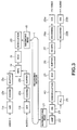
- Fig. 3 is a block diagram showing a circuit configuration of a recording/reproducing system using a modulating apparatus and a demodulating apparatus to which this invention is applied.
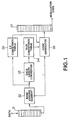
- Fig. 1 is a block diagram showing an actual circuit configuration of the modulating apparatus to which this invention is applied.
- Fig. 2 is a block diagram showing an actual circuit configuration of the demodulating apparatus to which this invention is applied.
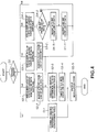
- Fig. 4 is a flowchart showing a modulating operation.
- Fig. 5 is a flowchart showing a demodulating operation.
- FIG. 1 is a block diagram showing an actual circuit configuration of the modulating apparatus
- Fig. 2 is a block diagram showing an actual circuit configuration of the demodulating apparatus
- Fig. 3 is a block diagram showing the circuit configuration of the entirety of a recording/reproducing system for recording a video signal or reproducing a recorded video signal by using the modulating apparatus and the demodulating apparatus.
- the recording system of the recording/reproducing system comprises, as shown in Fig. 3, an analog/digital converter (hereinafter referred to as A/D converter) 11 for converting a video signal to a digital signal, an encoder 12a for encoding the digital video signal from the A/D converter 11a to implement data compression thereto, a buffer memory 13a for storing video data from the encoder 12a, an A/D converter 11b for converting an audio signal to a digital signal, an encoder 12b for encoding the digital audio signal from the A/D converter 11b to implement data compression thereto, a buffer memory 13b for storing audio data from the encoder 12b, a multiplexer (hereinafter referred to as MPX) 14 for multiplexing video data and audio data from the buffer memories 13a, 13b, a circuit for adding an error correcting code (ECC) to data from the MPX 14 (hereinafter referred to as ECC circuit) 15, a modulating unit 30 for modulating the data to which the error correcting code from the E
- the A/D converter 11a converts a video signal delivered as an analog signal into a digital video signal.
- the encoder 12a is comprised of, e.g. , so called a predictive encoder, a discrete cosine transform (so called DCT) element, or a Huffman encoder, etc. for carrying out a predetermined coding, and adapted to allow the digital video signal delivered from A/D converter 11a to undergo motion compensating predictive-coding between pictures to reduce redundancy in the time base (axis) direction, and to reduce redundancy in the spatial direction by DCT and Huffman coding to carry out efficient coding to generate video data.
- the video data thus generated is temporarily stored into the buffer memory 13a.
- the A/D converter 11b converts an audio signal delivered as an analog signal into a digital audio signal.
- the encoder 12b is comprised of a predetermined encoder, and adapted to encode a digital audio signal delivered from the A/D converter 11b to implement data compression thereto to generate audio data.
- the audio data thus generated is temporarily stored into the buffer memory 13b.
- the MPX 14 reads out video data stored in the buffer memory 13a and audio data stored in the buffer memory 13b, e.g., in a manner caused to be synchronized with each other to multiplex such data and add a synchronizing (SYNC) signal, etc. thereto to output it in accordance with a predetermined format.
- SYNC synchronizing
- the ECC circuit 15 adds an error correcting code to data in which video data and audio data are multiplexed from the MPX 14 to deliver the error correcting code added data to the modulating unit 30.
- the modulating unit 30 converts data of a basic data length of m bits delivered from the MPX 14 into a variable length code (d, k; m, n; r) of a basic code length of n bits to allow the modulation code thus obtained to undergo, e.g., so called NRZI (Non Return to Zero Inverted) modulation to deliver it to recording head 16.
- NRZI Non Return to Zero Inverted
- the recording medium 1 is comprised of a recording medium such as an optical disc, a magnetic disc, or a magnetic tape, etc.
- the recording head 16 is comprised of an optical head or a magnetic head in correspondence with such a recording medium to carry out recording on the basis of a modulation code delivered from the modulating unit 30.
- a modulation code delivered from the modulating unit 30 For example, in the case where the recording medium 1 is assumed to be so called a compact disc (hereinafter referred to as CD) having a diameter of 12 cm, video data, etc. of moving picture is recorded with a recording capacitor which is greater six times or more than that of the existing CD on which audio data is recorded.
- CD compact disc
- the reproducing system of the recording/reproducing system comprises, as shown in Fig. 3, a reproducing head 21 for reproducing a reproduction signal from the recording medium 1, an amplifier 22 for amplifying the reproduction signal from the reproducing head 21, an equalizer (hereinafter referred to as EQ) 23 for equalizing the reproduction signal amplified by the amplifier 22, a clock reproducing element 24 for reproducing a clock from the equalized reproduction signal from the EQ23, a demodulating unit 40 for demodulating the reproduction signal from the EQ23 to reproduce data, an error correcting circuit 25 for carrying out error correction of the data reproduced at the demodulating unit 40, a buffer memory 26 for storing the error corrected data from the error correcting circuit 25, a demultiplexer (hereinafter referred to as DE-MPX) 27 for separating data from the buffer memory 26 into video data and audio data, a decoder 28a for decoding the video data separated at the DE-MPX 27 to reproduce a digital video signal, a D/A converter 29a for converting the
- the reproducing head 21 reproduces a reproduction signal from the recording medium 1.
- the amplifier 22 amplifies this reproduction signal.
- the EQ 23 waveform-equalizes the reproduction signal amplified at the amplifier 22 to deliver the waveform-equalized reproduction signal to the clock reproducing element 24 and the demodulating unit 40.
- the clock reproducing element 24 is comprised of, e.g., so called PLL (Phase Locked Loop), etc. to reproduce a clock by the clock component included in the reproduction signal.
- the demodulating unit 40 binarizes reproduction signal delivered from EQ 23, e.g., by using a clock delivered from the clock reproducing element 24, and carries out demodulation corresponding to modulation at the above-described modulating unit 30, i.e., converts, in reverse direction, variable length code (d, k; m, n; r) of a basic code length of n bits obtained binarization into data of a basic data length of m bits to reproduce reproduction data.
- variable length code d, k; m, n; r
- the error correcting circuit 25 carries out error correction of the reproduction data delivered from the demodulating unit 40.
- the buffer memory 26 temporarily stores the error corrected reproduction data.
- the DE-MPX 27 separates the reproduction data delivered from the buffer memory 26 into video data and audio data to deliver the video data to the demodulator 28a and to deliver audio data to the demodulator 28b.
- the demodulator 28a carries out decoding corresponding to coding at the above-described encoder 12a to reproduce a digital video signal.
- the D/A converter 29a converts the reproduced digital video signal to an analog signal to output a video signal.
- the decoder 28b carries out decoding corresponding to coding at the above-described encoder 12b to reproduce a digital audio signal.
- the D/A converter 29a converts the reproduced digital audio signal to an analog signal to output an audio signal.
- variable length code (d, k; m, n; r) is assumed to be, e.g., variable length code (4, 22; 2, 5; 5), i.e., it is assumed that d which is the minimum run of 0 is 4 bits, k which is the maximum run of 0 is 22 bits, m which is the basic data length is 2 bits, n which is the basic code length is 5 bits, and r which is the maximum binding length is 5,
- the second modulating circuit 36 includes a 2-5 conversion table for converting data of 2 bits where the binding length i is 1, which is not included in the 2-5 conversion table of the first modulating circuit 34 as shown in the following table 3, for example.
- code rule for converting data of "111111” in binary representation hereinafter referred to as data "111111”
- code rule for converting data of "111111” in binary representation hereinafter referred to as data "111111” into code "00001 00001 00000” is used for allowing the maximum run K of the variable length code obtained by conversion to be 22 bits or less.
- TABLE 3 DATA CODE i 1 11 00000 10 10000 111111 00001 00001 00000
- the shift register 31 shifts data delivered from ECC circuit 15 in units of m bits.
- the rank judging element 32 judges whether data caused to be four bits in total corresponds to the lower order 4 bits of the data portion of the 10-25 conversion table shown in the table 2 when the fourth bit from the Least Significant Bit (LSB) is converted to 1, i.e., judges the binding length i to be 2 at the time of data "0111”, “0110”, “0101”, “0100”, and passes on to the next rant at the time of data "0011", “0010", "0001", "0000".
- LSB Least Significant Bit
- the data length converter 33 adds dummy bits to the leading portion of m ⁇ i (i ⁇ r) bits delivered from the rank judging element 32 to form m ⁇ r bits, and converts a portion of data so as to become in correspondence with the data portion of the 10-25 conversion table.
- the flowchart of the operation of data length converter 33, first and second modulators 34, 36 and code generator 35 is shown in Fig. 4
- data "0111” delivered from the rank judging element 32 is converted into data "0000011111”
- data "0110” is converted into data "0000011110".
- the data length converter 33 is operative so that the binding length i is, e.g., 3, i.e., data is 6 bits, it adds dummy bits of 4 bits indicated by "0000" to the leading portion thereof to form data of 10 bits which is the same as that of the data portion of the 10-25 conversion table (step S3-1), and converts the fifth bit from LSB of the data thus formed into "1" so as to become in correspondence with the data portion of the 10-25 conversion table (step S3-2).
- data "001111” delivered from the rank judging element 32 is converted into data "0000011111”
- data "001110" is converted into data "0000011110".
- the first modulator 34 includes 10-25 conversion table shown in the table 1, and is operative to read out codes of the code portion with data delivered from the data length converter 33 being as readout address (step S2-3).
- data delivered from data length converter 33 is, e.g., "0000011111”
- code "01000 01000 01000 01000 00000” is outputted from the first modulator 34.
- the code generator 35 takes out specific bits of the code of 25 bits, i.e., n ⁇ i bits from LSB delivered from the first modulator 34 on the basis of the binding length i delivered from the above-described rank judging element 32 (step S2-4) to output it as a modulation code (step S2-5).
- n ⁇ i bits from LSB delivered from the first modulator 34 on the basis of the binding length i delivered from the above-described rank judging element 32 (step S2-4) to output it as a modulation code (step S2-5).
- the code generator 35 when the binding length i is 2, the code generator 35 outputs a modulation code "00100 00000”; when the binding length i is 3, it outputs a modulation code "01000 00100 00000”; and when the binding length i is 4, it outputs a modulation code "01000 01000 00100 00000", and when the binding length i is 5, it outputs a modulation code "01000 01000 01000 00100 00000".
- Modulation codes having code length of n ⁇ i bits based on the binding length i thus obtained are delivered to shift register 37, and are then delivered from the shift register 37 to, e.g., a NRZI modulator (not shown) at a predetermined transfer rate.
- the NRZI modulated modulation code is sent to the recording head 16.
- this modulating apparatus 30 can convert data of 4 bits, 6 bits, 8 bits and 10 bits into variable length codes of 10 bits, 15 bits, 20 bits and 25 bits only by the 10-25 conversion table of the first modulator 34.
- 4-10 conversion table, 6-15 conversion table and 8-20 which were required in the conventional device are unnecessary.
- the recording head 16 carries out recording with respect to the recording medium 1 comprised of, e.g., a magneto-optical disc on the basis of the NRZI modulated modulation code delivered from the modulator 30 as described above.
- the bit interval of data delivered to the modulator 30 is assumed to be T
- the circuit scale of the first modulator 34 can become compact.
- the first demodulator 44 includes, as the first reverse conversion table, a reverse conversion table corresponding to the 10-25 conversion table that the above-described first modulator 34 has, i.e., at least one reverse conversion table where the code portion of the above-described 10-25 conversion table shown in Fig.
- the second demodulator 46 includes, as a second reverse conversion table, a reverse conversion table for converting in reverse direction a variable length code of 5 bits where the binding length i is 1 which is not included in the 25-10 reverse conversion table of the first demodulator 44, i.e., a 5-2 reverse conversion table where the code portion of the 2-5 conversion table (shown in Table 3) that the above-described second demodulator 36 has is taken as a readout address and the data portion thereof is as an output.
- a second reverse conversion table for converting in reverse direction a variable length code of 5 bits where the binding length i is 1 which is not included in the 25-10 reverse conversion table of the first demodulator 44, i.e., a 5-2 reverse conversion table where the code portion of the 2-5 conversion table (shown in Table 3) that the above-described second demodulator 36 has is taken as a readout address and the data portion thereof is as an output.
- the shift register 41 shifts the reproduced variable length code in units of n bits.
- the rank judging element 42 judges the binding length i of the variable length code delivered in units of n bits.
- the number of bits from a boundary to the next boundary is 5, it judges the binding length i to be 1; when that number is 10, it judges the binding length i to be 2; when that number is 15, it judges the binding length i to be 3; when that number is 20, it judges the binding length i to be 4; and when that number is 25, it judges binding length i to be 5.
- binding length i is judged to be 1 with respect to the variable length code "00001 00001 00000".
- the code length converter 43 adds dummy bits to the leading portion of n ⁇ i (i ⁇ r) bits delivered from the rank judging element 43 to form a code of n ⁇ r bits to deliver a code of n ⁇ r bits to the first demodulator 44.
- the code length converter 43 adds dummy bits of 10 bits indicated by "01000 01000" to the leading portion thereof to form a code of 25 bits which is the same as that of the code portion of the 25-10 reverse conversion table (step S13-1). Similarly, when the binding length i is 4, the code length converter 43 adds dummy bits "01000" of 5 bits to the leading portion thereof (step S14-1).
- the first demodulator 44 includes, as described above, a 25-10 reverse conversion table for outputting data portion of the 10-25 conversion table shown in the table 1 with the code portion thereof being as a readout address, and serves to read out data of the data portion with a code of 25 bits delivered from the code length converter 43 being as a readout address (steps S12-2, S13-2, S14-2, S15-1).
- code delivered from the code length converter 43 is "01000 01000 01000 01000 00000"
- data "0000011111" is outputted from the first demodulator 44.
- variable length codes "00100 00000”, “01000 00100 00000”, “01000 01000 00100 00000”, and "01000 01000 01000 00100 00000" are delivered, data "00000 11110" of 10 bits are uniformly outputted from the first demodulator 44 by the 25-10 reverse conversion table.
- the data generator 45 takes out specific bits of data of 10 bits, i.e., m ⁇ i bits from LSB delivered from the first demodulator 44 on the basis of the binding length i delivered from the above-described rank judging element 42, and converts the specific bits of the data thus taken out to output them as reproduction data.
- the data generator 45 takes out 4 bits from LSB (step S12-4), and converts the fourth bit from LSB to "0" (step S12-3) to output "0111" as reproduction data. Further, when 3 is delivered as the binding length i with respect to the same data "0000011111", the data generator 45 takes out 6 bits from LSB (step S12-4), and converts the fifth bits from LSB to "0" (step S13-3) to output "001111" as reproduction data.
- step S14-5 When the third bit from LSB is "1", only the third bit is inverted into "0" (step S14-5). It is to be noted that while, in this case, 8 bit data is taken out from 10 bits from the demodulator 44 thereafter to convert data, data is converted thereafter to take out 8 bits (This similarly applies to other binding lengths). In Fig. 5, the latter approach was adopted.
- the data generator 45 respectively outputs reproduction data "0110", "001110”, "0011010", "0000011110".
- Reproduction data having a data length (m ⁇ i bits) based on the binding length i obtained in this way is delivered to the shift register 47.
- This data is delivered from the shift register 47 to the above-described error correcting circuit 25 at a predetermined transfer rate (step S12-5).
- this demodulating apparatus 40 can convert, in reverse direction, variable length codes of 10 bits, 15 bits, 20 bits and 25 bits into data of 4 bits, 6 bits, 8 bits and 10 bits only by the 25-10 reverse conversion table of the first demodulator 44.
- 10-4 reverse conversion table, 15-6 reverse conversion table, and 10-8 reverse conversion table which were required in the conventional apparatus are not necessary.
- reverse conversion tables which were required every binding length i in the prior art can be reduced, i.e., 68 code rules which were required in the prior art can be reduced to 35 code rules.
- the circuit scale of the first demodulator 44 can become compact.
- variable length code employed in this invention is not limited to variable length code (4, 22; 2, 5; 5) of the above-described embodiment, but may be applied to, e.g., variable length code (d, k; m, n; r) where r is not 1.
- the demodulating apparatus is adapted to judge the binding length i of the variable length code to uniformly convert, in reverse direction, a variable length code of n ⁇ i bits into data of m ⁇ r bits by a first reverse conversion table for converting, in reverse direction, variable length code of n ⁇ r bits where the binding length i is the maximum binding length r, and including at least one reverse conversion table where the binding length i is less than r to take out specific bits from the data on the basis of the binding length i to output them as reproduction data, and to convert, in reverse direction, variable length code of n ⁇ i bits which cannot be converted in reverse direction by the first conversion table into data of m ⁇ i bits by the second reverse conversion table to output it as reproduction data, thereby making it possible to reduce the number of conversion tables which were required every binding length i in the conventional apparatus thus to allow the circuit scale to become compact and to reduce the cost.
Landscapes
- Engineering & Computer Science (AREA)
- Theoretical Computer Science (AREA)
- Signal Processing (AREA)
- Human Computer Interaction (AREA)
- Physics & Mathematics (AREA)
- General Engineering & Computer Science (AREA)
- General Physics & Mathematics (AREA)
- Signal Processing For Digital Recording And Reproducing (AREA)
Applications Claiming Priority (3)
| Application Number | Priority Date | Filing Date | Title |
|---|---|---|---|
| JP6223893 | 1993-03-22 | ||
| JP62238/93 | 1993-03-22 | ||
| JP05062238A JP3127655B2 (ja) | 1993-03-22 | 1993-03-22 | 変調装置及び復調装置 |
Publications (3)
| Publication Number | Publication Date |
|---|---|
| EP0617517A2 true EP0617517A2 (de) | 1994-09-28 |
| EP0617517A3 EP0617517A3 (de) | 1995-07-19 |
| EP0617517B1 EP0617517B1 (de) | 1999-09-22 |
Family
ID=13194378
Family Applications (1)
| Application Number | Title | Priority Date | Filing Date |
|---|---|---|---|
| EP94104213A Expired - Lifetime EP0617517B1 (de) | 1993-03-22 | 1994-03-17 | Modulations-, und Demodulationsverfahren und Vorrichtung |
Country Status (7)
| Country | Link |
|---|---|
| US (1) | US5528236A (de) |
| EP (1) | EP0617517B1 (de) |
| JP (1) | JP3127655B2 (de) |
| KR (1) | KR100288463B1 (de) |
| CN (1) | CN1053987C (de) |
| AU (1) | AU672666B2 (de) |
| DE (1) | DE69420767T2 (de) |
Cited By (2)
| Publication number | Priority date | Publication date | Assignee | Title |
|---|---|---|---|---|
| EP0744838A4 (de) * | 1994-12-12 | 1999-05-06 | Sony Corp | Datenkodier- und datendekodierverfahren |
| EP0903864A3 (de) * | 1997-09-19 | 1999-09-15 | Sony Corporation | Demodulator, Demodulationsverfahren und Übertragungsträger |
Families Citing this family (6)
| Publication number | Priority date | Publication date | Assignee | Title |
|---|---|---|---|---|
| US6091347A (en) * | 1997-05-23 | 2000-07-18 | Sony Corporation | Device and method for modulation and transmission medium |
| JP3760961B2 (ja) * | 1997-09-11 | 2006-03-29 | ソニー株式会社 | 変調装置および変調方法、復調装置および復調方法、並びに記録媒体 |
| JP3870573B2 (ja) * | 1998-08-24 | 2007-01-17 | ソニー株式会社 | 変調装置および方法、記録媒体、並びに復調装置および方法 |
| KR100648360B1 (ko) * | 2000-02-07 | 2006-11-23 | 엘지전자 주식회사 | 광기록매체의 데이터 변/복조 장치 |
| KR100726083B1 (ko) * | 2000-04-14 | 2007-06-08 | 엘지전자 주식회사 | 광기록매체와 그의 데이터 변/복조 방법 및 장치 |
| JP2012252749A (ja) * | 2011-06-03 | 2012-12-20 | Renesas Electronics Corp | 光ディスク記録装置、記録データ伝送方法および半導体装置 |
Family Cites Families (21)
| Publication number | Priority date | Publication date | Assignee | Title |
|---|---|---|---|---|
| US3689899A (en) * | 1971-06-07 | 1972-09-05 | Ibm | Run-length-limited variable-length coding with error propagation limitation |
| JPS5665313A (en) * | 1979-10-29 | 1981-06-03 | Sony Corp | Data converting circuit |
| DE3502808A1 (de) * | 1985-01-29 | 1986-07-31 | Maschinenfabrik Fr. Niepmann GmbH u. Co, 5820 Gevelsberg | Vorrichtung zum erfassen und loesen des anfangs einer bobine |
| JP2592054B2 (ja) * | 1986-01-31 | 1997-03-19 | シャープ株式会社 | データ記録方法 |
| DE3825960A1 (de) * | 1987-09-01 | 1989-03-16 | Hitachi Ltd | Verfahren und vorrichtung zur digitalen informationscodierung |
| JPH01118274A (ja) * | 1987-10-30 | 1989-05-10 | Canon Inc | デジタルデータの記録方式 |
| FR2627337B1 (fr) * | 1988-02-17 | 1990-06-08 | Thomson Csf | Procede de codage et procede de decodage a longueur variable, dispositif de codage et dispositif de decodage pour la mise en oeuvre de ce proced |
| US4985700A (en) * | 1988-03-01 | 1991-01-15 | Canon Kabushiki Kaisha | Variable-length coding/decoding device |
| JP2713574B2 (ja) * | 1988-03-26 | 1998-02-16 | 株式会社日立製作所 | アドレスマーク発生方法および回路 |
| JPH03145223A (ja) * | 1989-10-30 | 1991-06-20 | Toshiba Corp | 可変長符号復調装置 |
| EP0442548B1 (de) * | 1990-01-30 | 1995-08-02 | Laboratoires D'electronique Philips S.A.S. | Vorrichtungen zur variablen Längen-Kodierung und Dekodierung von digitalen Daten |
| US5034742A (en) * | 1990-06-19 | 1991-07-23 | The United States Of America As Represented By The Secretary Of The Navy | Message compression encoder and encoding method for a communication channel |
| US5138314A (en) * | 1990-07-18 | 1992-08-11 | Sony Corporation | Method for converting and/or detecting data |
| JPH0479421A (ja) * | 1990-07-18 | 1992-03-12 | Toshiba Corp | 可変長符号化装置および可変長復号化装置 |
| US5173694A (en) * | 1990-10-29 | 1992-12-22 | International Business Machines Corporation | Binary data encoding and decoding using a rate 2/5 (2,18,2) code |
| EP0511498B1 (de) * | 1991-03-30 | 1998-12-09 | Kabushiki Kaisha Toshiba | Kodiereinrichtung für digitale Signale mit verbesserter Kanal-Blockkodierung |
| GB2260458B (en) * | 1991-10-04 | 1995-03-22 | Sony Broadcast & Communication | Data decoder |
| JP3334810B2 (ja) * | 1992-02-14 | 2002-10-15 | ソニー株式会社 | 符号化方法、再生方法、および、再生装置 |
| TW219416B (de) * | 1992-03-10 | 1994-01-21 | Sony Co Ltd | |
| JP3428039B2 (ja) * | 1992-06-30 | 2003-07-22 | ソニー株式会社 | 同期信号検出器、同期信号検出方法及び復号化装置 |
| US5388993A (en) * | 1992-07-15 | 1995-02-14 | International Business Machines Corporation | Method of and system for demonstrating a computer program |
-
1993
- 1993-03-22 JP JP05062238A patent/JP3127655B2/ja not_active Expired - Fee Related
-
1994
- 1994-03-15 US US08/213,234 patent/US5528236A/en not_active Expired - Fee Related
- 1994-03-16 AU AU57861/94A patent/AU672666B2/en not_active Ceased
- 1994-03-17 DE DE69420767T patent/DE69420767T2/de not_active Expired - Fee Related
- 1994-03-17 EP EP94104213A patent/EP0617517B1/de not_active Expired - Lifetime
- 1994-03-21 KR KR1019940005593A patent/KR100288463B1/ko not_active Expired - Fee Related
- 1994-03-22 CN CN94104898A patent/CN1053987C/zh not_active Expired - Fee Related
Cited By (3)
| Publication number | Priority date | Publication date | Assignee | Title |
|---|---|---|---|---|
| EP0744838A4 (de) * | 1994-12-12 | 1999-05-06 | Sony Corp | Datenkodier- und datendekodierverfahren |
| EP0903864A3 (de) * | 1997-09-19 | 1999-09-15 | Sony Corporation | Demodulator, Demodulationsverfahren und Übertragungsträger |
| US6313764B1 (en) | 1997-09-19 | 2001-11-06 | Sony Corporation | Demodulating device, demodulating method and transmission medium |
Also Published As
| Publication number | Publication date |
|---|---|
| CN1053987C (zh) | 2000-06-28 |
| US5528236A (en) | 1996-06-18 |
| KR100288463B1 (ko) | 2001-05-02 |
| EP0617517A3 (de) | 1995-07-19 |
| DE69420767T2 (de) | 2000-03-02 |
| AU5786194A (en) | 1994-09-29 |
| JPH06276100A (ja) | 1994-09-30 |
| KR940022242A (ko) | 1994-10-20 |
| CN1096392A (zh) | 1994-12-14 |
| JP3127655B2 (ja) | 2001-01-29 |
| DE69420767D1 (de) | 1999-10-28 |
| EP0617517B1 (de) | 1999-09-22 |
| AU672666B2 (en) | 1996-10-10 |
Similar Documents
| Publication | Publication Date | Title |
|---|---|---|
| KR100263686B1 (ko) | 부호화 방식 | |
| CA1151742A (en) | Method and apparatus for communicating digital information words by error-correction encoding | |
| US8301014B2 (en) | Signal recording/reproducing method and apparatus, signal record medium and signal transmission/reception method and apparatus | |
| GB2238203A (en) | Video compression using interframe and intraframe coding for each frame | |
| EP0492704B1 (de) | Anordnung zum Aufzeichnen von Takteinlauf-Codewörtern in einer Spur auf einem magnetischen Aufzeichnungsträger | |
| KR950020674A (ko) | 고속 비디오 편집 시스템 | |
| KR100296527B1 (ko) | 디지탈영상신호를가변길이인코딩및전송하는장치및방법 | |
| US5440432A (en) | Dubbing system for digital information | |
| EP0617517B1 (de) | Modulations-, und Demodulationsverfahren und Vorrichtung | |
| US6055664A (en) | Encoding device and decoding device suitable for dubbing | |
| US5325371A (en) | Coding/decoding apparatus | |
| JP2937664B2 (ja) | ディジタルvtrのエラー訂正方法及び装置 | |
| US5657013A (en) | Data recording apparatus | |
| KR950009670A (ko) | 디지탈 브이씨알의 기록/재생장치 | |
| JPH05344162A (ja) | データ伝送装置 | |
| CA2026632C (en) | Information data recording/reproducing apparatus | |
| US4377805A (en) | Magnetic recording | |
| JPH0846526A (ja) | ディジタル信号の符号化方法、装置、復号装置及び符号化復号化方法 | |
| JPH0363859B2 (de) | ||
| JP3499940B2 (ja) | 符号化及び復号化方法 | |
| US7167524B2 (en) | Method of inserting sync data in modulated data and recording medium containing the sync data | |
| EP0575086A2 (de) | Informationsaufzeichnungs- und -wiedergabegerät | |
| JPS58223977A (ja) | 映像信号デイジタル記録再生装置 | |
| JPH02156479A (ja) | メモリ装置の記憶再生方式 | |
| JPH05114248A (ja) | 磁気記録再生装置 |
Legal Events
| Date | Code | Title | Description |
|---|---|---|---|
| PUAI | Public reference made under article 153(3) epc to a published international application that has entered the european phase |
Free format text: ORIGINAL CODE: 0009012 |
|
| AK | Designated contracting states |
Kind code of ref document: A2 Designated state(s): DE FR GB |
|
| PUAL | Search report despatched |
Free format text: ORIGINAL CODE: 0009013 |
|
| AK | Designated contracting states |
Kind code of ref document: A3 Designated state(s): DE FR GB |
|
| 17P | Request for examination filed |
Effective date: 19960116 |
|
| 17Q | First examination report despatched |
Effective date: 19980610 |
|
| GRAG | Despatch of communication of intention to grant |
Free format text: ORIGINAL CODE: EPIDOS AGRA |
|
| GRAG | Despatch of communication of intention to grant |
Free format text: ORIGINAL CODE: EPIDOS AGRA |
|
| GRAH | Despatch of communication of intention to grant a patent |
Free format text: ORIGINAL CODE: EPIDOS IGRA |
|
| GRAH | Despatch of communication of intention to grant a patent |
Free format text: ORIGINAL CODE: EPIDOS IGRA |
|
| GRAA | (expected) grant |
Free format text: ORIGINAL CODE: 0009210 |
|
| AK | Designated contracting states |
Kind code of ref document: B1 Designated state(s): DE FR GB |
|
| REF | Corresponds to: |
Ref document number: 69420767 Country of ref document: DE Date of ref document: 19991028 |
|
| ET | Fr: translation filed | ||
| PLBE | No opposition filed within time limit |
Free format text: ORIGINAL CODE: 0009261 |
|
| 26N | No opposition filed | ||
| REG | Reference to a national code |
Ref country code: GB Ref legal event code: IF02 |
|
| PGFP | Annual fee paid to national office [announced via postgrant information from national office to epo] |
Ref country code: FR Payment date: 20030310 Year of fee payment: 10 |
|
| PGFP | Annual fee paid to national office [announced via postgrant information from national office to epo] |
Ref country code: GB Payment date: 20030312 Year of fee payment: 10 |
|
| PGFP | Annual fee paid to national office [announced via postgrant information from national office to epo] |
Ref country code: DE Payment date: 20030327 Year of fee payment: 10 |
|
| PG25 | Lapsed in a contracting state [announced via postgrant information from national office to epo] |
Ref country code: GB Free format text: LAPSE BECAUSE OF NON-PAYMENT OF DUE FEES Effective date: 20040317 |
|
| PG25 | Lapsed in a contracting state [announced via postgrant information from national office to epo] |
Ref country code: DE Free format text: LAPSE BECAUSE OF NON-PAYMENT OF DUE FEES Effective date: 20041001 |
|
| GBPC | Gb: european patent ceased through non-payment of renewal fee |
Effective date: 20040317 |
|
| PG25 | Lapsed in a contracting state [announced via postgrant information from national office to epo] |
Ref country code: FR Free format text: LAPSE BECAUSE OF NON-PAYMENT OF DUE FEES Effective date: 20041130 |
|
| REG | Reference to a national code |
Ref country code: FR Ref legal event code: ST |