EP0618162A2 - Ruban adhésif de raccordement de bande pour une bobine nouvelle - Google Patents
Ruban adhésif de raccordement de bande pour une bobine nouvelle Download PDFInfo
- Publication number
- EP0618162A2 EP0618162A2 EP93118741A EP93118741A EP0618162A2 EP 0618162 A2 EP0618162 A2 EP 0618162A2 EP 93118741 A EP93118741 A EP 93118741A EP 93118741 A EP93118741 A EP 93118741A EP 0618162 A2 EP0618162 A2 EP 0618162A2
- Authority
- EP
- European Patent Office
- Prior art keywords
- adhesive
- adhesive tape
- layer
- strip
- tape
- Prior art date
- Legal status (The legal status is an assumption and is not a legal conclusion. Google has not performed a legal analysis and makes no representation as to the accuracy of the status listed.)
- Withdrawn
Links
Images




Classifications
-
- B—PERFORMING OPERATIONS; TRANSPORTING
- B65—CONVEYING; PACKING; STORING; HANDLING THIN OR FILAMENTARY MATERIAL
- B65H—HANDLING THIN OR FILAMENTARY MATERIAL, e.g. SHEETS, WEBS, CABLES
- B65H19/00—Changing the web roll
- B65H19/10—Changing the web roll in unwinding mechanisms or in connection with unwinding operations
- B65H19/102—Preparing the leading end of the replacement web before splicing operation; Adhesive arrangements on leading end of replacement web; Tabs and adhesive tapes for splicing
-
- C—CHEMISTRY; METALLURGY
- C09—DYES; PAINTS; POLISHES; NATURAL RESINS; ADHESIVES; COMPOSITIONS NOT OTHERWISE PROVIDED FOR; APPLICATIONS OF MATERIALS NOT OTHERWISE PROVIDED FOR
- C09J—ADHESIVES; NON-MECHANICAL ASPECTS OF ADHESIVE PROCESSES IN GENERAL; ADHESIVE PROCESSES NOT PROVIDED FOR ELSEWHERE; USE OF MATERIALS AS ADHESIVES
- C09J7/00—Adhesives in the form of films or foils
- C09J7/20—Adhesives in the form of films or foils characterised by their carriers
-
- B—PERFORMING OPERATIONS; TRANSPORTING
- B65—CONVEYING; PACKING; STORING; HANDLING THIN OR FILAMENTARY MATERIAL
- B65H—HANDLING THIN OR FILAMENTARY MATERIAL, e.g. SHEETS, WEBS, CABLES
- B65H2301/00—Handling processes for sheets or webs
- B65H2301/40—Type of handling process
- B65H2301/46—Splicing
- B65H2301/4606—Preparing leading edge for splicing
- B65H2301/4607—Preparing leading edge for splicing by adhesive tape
-
- B—PERFORMING OPERATIONS; TRANSPORTING
- B65—CONVEYING; PACKING; STORING; HANDLING THIN OR FILAMENTARY MATERIAL
- B65H—HANDLING THIN OR FILAMENTARY MATERIAL, e.g. SHEETS, WEBS, CABLES
- B65H2301/00—Handling processes for sheets or webs
- B65H2301/40—Type of handling process
- B65H2301/46—Splicing
- B65H2301/4606—Preparing leading edge for splicing
- B65H2301/46078—Preparing leading edge for splicing the adhesive tab or tab having a cleavable or delaminating layer
Definitions
- a new web roll consisting of a new web wound around a roll core, is brought to the same rotational speed as the running web during the start-up time.
- the new web is then bonded to the running web, often using an adhesive, which connects the first layer of the new web roll to the rear end of the running web ending.
- the new web roll usually has a means whereby the first layer of the new web roll can be held in place during its start-up rotation.
- this first layer does not have to be held too firmly, because it must be able to come loose when connecting and follow the running path.
- double-sided adhesive tape was used in conventional web connection techniques in order to hold the leading edge of the web and thus the first web layer on the new roll.
- Adhesive web tape of this type is disclosed in US Patent No. 4,905,924 - Moore. In this patent, one side of the tape holds the first layer of a new web roll in place by holding the leading edge of the first layer with the tape is covered. The other side of the adhesive tape has an adhesive layer on the rear part of the tape, on which a running web can adhere.
- the adhesive tape separates along an embossed profile, so that the first layer of the new web roll can move freely with the rear end of the running web and the front part of the adhesive tape to a second The position of the new web roll remains stuck.
- the type described in the patent has some disadvantages.
- the adhesive bond between the running web and the first layer of the new web roll must be strong enough to separate the adhesive tape. In the event that the adhesive tape does not separate, the adhesive bond between the running web and the first layer of the new web can become ineffective.
- the adhesive tape must not separate at an early point in time.
- the present invention provides a new web roll comprising the following features: a roll core; a new web wound around the roll core with a first layer having a leading edge and a second layer, the first layer having an inner surface and an outer surface; at least one strip of double-sided release adhesive tape with a highly tacky adhesive on one side and a weakly adhesive on the other side; at least one strip of double-sided adhesive tape with a highly tacky adhesive on both sides of the adhesive; the release tape is attached between the inner surface of the first layer and the second layer near the leading edge and holds the leading edge in place during the start-up rotation of the new web roll; and one adhesive side of the adhesive tape is attached to the outer surface of the first layer near the leading edge, and the other adhesive side is thus free to be connected to a running web.
- the present invention also provides an adhesive tape for connecting a first layer of a new web roll to a running web and for holding the first layer a second layer of the new web roll prior to joining, comprising: a carrier strip having an inner surface and an outer surface; a first means for connecting the outer surface of the carrier strip to the running web; second means for connecting a rear portion of the carrier strip to the first layer of the new web roll; and a third means for connecting a front portion of the carrier strip to the second layer of the new web roll, the third means allowing the front portion of the carrier strip to separate from the second layer of the new web roller when connected.
- the highly tacky adhesive enables effective bonding and at the same time that the low tack adhesive and thus the first layer are detached from the new web roll.
- Another advantage of the present invention is that the weakly tacky adhesive enables the first layer of the new web roll to be separated effortlessly when it is connected, and fixes this first layer to the new web roll when it is rotated before it is connected.
- the weakly tacky adhesive has the property of "slipping", as a result of which excessive stresses resulting in the connection profile are relieved as a result of temperature and moisture-related shrinkage of the paper layers.
- An additional advantage of the present invention is the gluing of the front edge of the new web roll, which prevents air from penetrating under the first layer of the new web roll and prematurely lifting it off the web roll.
- FIGS. 1 and 1A show a running roller 6, from which a web 8 is guided into a printing machine, not shown.
- a new web roll 10 is also shown which replaces the running web roll 6 when it has ended.
- the new web roll 10 has a core 12, around which a new web 14 is wound.
- the new web roll 10 has a first layer 16 with a front edge 18.
- the first layer 16 of the new web roll 10 is connected to the rear end of the running web 8. The connection comes about by gluing the first layer 16 of the new web roll 10 to the running web 8, as is described in the following exemplary embodiments.
- the new web roll 10 is accelerated and brought to the rotational speed of the running web roll 6 in order to avoid additional web tension at the time of the connection.
- the front edge 18 of the first layer 16 must be kept in place. If this does not happen, the leading edge 18 will flutter and hang down and the new web 14 will unwind, making the connection impossible.
- the front edge 18 and the first layer 16 must also be able to come free when connected to the running web 8 so that the new web 14 can unwind from its roll 10.
- the present invention involves the use of double-sided adhesive tapes, some of which have a different tackiness to allow for effective bonding.
- An embodiment of the present invention is shown in FIG. 2.
- the new web roll 10 Before the new web roll 10 is placed near the running web 8, it is prepared for the connection.
- the new web roll 10 has a first layer 16 with an outer surface 28 and an inner surface 30, and one second layer 36 with an outer surface 38, as shown in FIG. 2.
- a long strip of double-sided release adhesive tape 20 with an inner adhesive side 22 and an outer adhesive side 24 between the inner surface 30 of the first layer 16 and the outer surface 38 of the second layer 36 near the Front edge 18 attached.
- the separating adhesive tape 20 extends over the entire width of the new web 14, thereby preventing the web from hanging down during the start-up rotation of the new web roll 10.
- the details of the release tape 20 are explained below.
- the holding adhesive tape 40 extends over the entire width of the new web roll 10.
- an adhesive-free gap 46 can be provided, where a belt drive drives the new web roll 10 for the start-up rotation.
- the inner adhesive side 42 and the outer adhesive side 44 of the holding adhesive tape 40 are provided with a highly tacky adhesive.
- This strong stickiness of the adhesive creates a strong connection between the first layer 16 of the new web and the running web 8, when the outer adhesive side 44 comes into contact with the running web 8.
- the adhesive strength of the highly tacky adhesive depends on the characteristic properties of the respective printing press. At the very least, the highly tacky adhesive must have sufficient adhesive strength to firmly bond the first layer of the new web to the running web and to be able to maintain this connection under all given conditions within the printing press itself.
- the outer adhesive side 24 of the separating adhesive tape 20 is provided with a weakly tacky adhesive, in contrast to the strong stickiness of the aforementioned adhesive, and the inner adhesive side 22 is provided with a highly tacky adhesive.
- the outer adhesive side 24 with the weaker stickiness separates when the first layer 16 of the new web is pulled from the running web 8 by the holding adhesive tape 40. Since both adhesive sides 42 and 44 of the holding adhesive tape 40 are provided with highly tacky adhesive, the strong connection between the first layer 16 of the new web and the running web 8 will not break. Rather, the weaker connection with the weakly tacky adhesive will yield on the outer adhesive side 24 of the separating adhesive tape, as a result of which the first layer 16 can separate from the second layer 36 and the rest of the new web 14 can unwind.
- Fig. 2A shows the effect of the arrangement in Fig. 2 after connection.
- the first layer 16 of the new web is therefore connected to the running web 8 by means of double-sided adhesive tape 40, the highly tacky adhesive forming a strong connection.
- the adhesive side 24 carries a low-tack adhesive
- the adhesive side 22 carries one very sticky adhesive. Therefore, in the connection process shown, the weak connection formed with the weakly tacky adhesive between the adhesive side 24 and the inner surface 30 of the first layer 16 is broken.
- the separating adhesive tape 20 remains on the second layer 36, since it is connected to its inner adhesive surface 22 by a highly tacky adhesive.
- the separating adhesive tape 20 according to FIG. 2 can also be equipped with a weakly tacky adhesive on the inner adhesive side 22 and with a strongly tacky adhesive on the outer adhesive side 24.
- the only effect with a low-tack adhesive on the inner adhesive side 22 is that the release adhesive tape 20 with the first layer 16 instead of the second Layer 36 remains connected.
- the first layer 16 of the new web is connected to the running web 8 by means of a holding adhesive tape 40 which forms a strong connection with the highly tacky adhesive.
- the adhesive side 22 is provided with a weakly tacky adhesive and the adhesive side 24 is provided with a highly tacky adhesive.
- the weak adhesive bond formed with the weakly tacky adhesive between the adhesive side 22 and the outer surface 38 of the second layer 36 of the new web is interrupted after the connection, as shown.
- the front edge 18 and the first layer 16 of the new web are held in place before being connected by the release adhesive tape 20.
- One side of the separating adhesive tape 20 with weaker stickiness forms a weak adhesive connection, but this connection should be strong enough that it might all be present during the start-up rotation of the new web roll 10 before the connection can withstand occurring forces.
- the separating adhesive tape 20 can be provided along the entire width of the front edge 18. This arrangement prevents air from getting between the first layer 16 and the second layer 36 of the new web, thereby also reducing the forces that could break the bond with the low tack adhesive. It is pointed out that if the weakly tacky connection is strong enough, instead of a single long adhesive strip, several strips or adhesive can be applied intermittently.
- the weakly tacky connection must be strong enough to prevent the first layer 16 from separating before being connected, it must also be weak enough so that the first layer 16 separates easily when connected.
- the connection formed by the low-tack adhesive must be weaker than the connection with the high-tack adhesive, and must also be weaker than the web itself, so that the separation of the first layer 16 from the second layer 36 can take place.
- the person skilled in the art can, depending on the given conditions of the printing press used, i.e. according to the speed of rotation of the web rolls, the forces occurring within the printing press and the strength of the web to be used, select the required high tack and low tack adhesive for the purposes of this invention.
- the use of the release tape 20 to hold the leading edge 18 in place prior to joining is advantageous because it is easy to attach and provides a smooth connection.
- the strength of the connection is easy to determine when using adhesive tape, since the exact area of the connection is then known.
- the adhesive tape 40 it would also be possible to apply a highly tacky adhesive directly to the outer surface 28 of the first layer 16 near the front edge 18. It would also be possible to use a double-sided release adhesive tape 20 with weakly tacky adhesive on both sides 22 and 24.
- a long strip of double-sided adhesive tape 80 with an inner adhesive side 82 and an outer adhesive side 84 is applied along the outer surface 68 of the carrier strip 60. Both sides, namely the inner and the outer adhesive side 82 and 84, are provided with a highly tacky adhesive.
- the inner adhesive side 82 of the holding adhesive tape 80 is connected to the outer surface 68 of the carrier strip 60 and forms a strong adhesive connection.
- the outer adhesive side 84 remains free for the adhesive connection of the first layer 16 of the new web to the running web 6, as described below.
- a long strip of double-sided adhesive bonding tape 90 is provided.
- the connecting adhesive tape 90 has an inner adhesive side 92 and an outer adhesive side 94, each with a highly tacky adhesive.
- the outer adhesive side 94 connects to a rear part 62 of the inner surface 70 of the Carrier strip 60.
- the inner adhesive side 92 connects to the outer surface 28 of the first layer 16, near the front edge 18 of the new web.
- the connecting adhesive tape 90 creates a strong connection between the carrier strip 60 and the first layer 16.
- 3A shows the effect of the weakly tacky adhesive on the outer adhesive side 104 of the release adhesive tape 100 after the connection.
- the running web 8 comes into contact with the outer adhesive side 84 of the holding adhesive tape 80, a connection with strongly tacky adhesive is formed between the carrier strip 60 and the running web 8. Then the running web 8 pulls the carrier strip 60, and the connecting strip 90 in turn pulls the first layer 16.
- the weak adhesive connection between the carrier strip 60 and the separating adhesive strip 100 which has formed with the outer adhesive side 104, is released.
- the first layer 16 of the new web 14 is thus free to unwind and follow the running web 8.
- the separating adhesive tape 100 remains connected to the second layer 36.
- FIG. 3 shows the effect after the connection when the low-tack adhesive is on the inner adhesive side 102 (instead of on the outer adhesive side 104, as shown in FIG. 3A).
- the running web 8 comes into contact with the outer adhesive side 84 of the holding adhesive tape 80, a connection with strongly tacky adhesive is formed between the carrier strip 60 and the running web 8.
- the running web 8 then pulls the carrier strip 60, which in turn pulls the first layer 16 through the connecting adhesive tape 90.
- the weak adhesive connection formed with the inner adhesive side 102 between the second layer 36 and the separating adhesive tape 100 is released.
- the separating adhesive tape 100 remains connected to the carrier strip 60 by the strong connection formed with the highly tacky adhesive on its outer adhesive side 104.
- the first layer 16 of the new web 14 is thus free to unwind and to follow the running web 8.
- release adhesive tape 100, the connecting adhesive tape 90 and the holding adhesive tape 80 can all be connected to the carrier strip 60 before the new web roll 10 is prepared.
- the complete assembly, consisting of carrier strips 60 and the adhesive tapes 80, 90 and 100 can then be applied as a single long composite strip or as a series of composite strips directly above the web edge 18.
- the carrier strip 60 and the Adhesive tapes 80, 90 and 100 are applied directly to the new web roll 10.
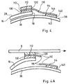
- FIG. 4 shows an embodiment of the invention similar to that shown in FIG. 3 with the differences described below.
- 4 comprises a carrier strip 110 with a rear part 112 and a front part 114.
- a double-sided adhesive tape 130 is provided in order to close the rear part 112 of the carrier strip 110 with the first layer 16 near the front edge 18 of the new web connect.
- a double-sided adhesive tape 120 is provided to connect the carrier strip 110 to the running web 8 when the webs are joined (as shown in FIG. 4A).
- the holding adhesive tape 120 and the connecting adhesive tape 130 are both provided with a highly tacky adhesive on both sides, as in the embodiment shown in FIG. 3.
- the adhesive tape 120 of the embodiment in FIG. 4 connects with the carrier strip 110 only on its rear part 112.
- the carrier strip 110 is also provided with a perforation 116.
- the perforation 116 extends along the entire length of the carrier strip 110 and enables the front part 114 to be separated from the rear part 112, as described below.
- a double-sided release adhesive tape 140 with an inner adhesive side 142 and an outer adhesive side 144 is applied between the second layer 36 of the new web and the front part 114 of the carrier strip 110.
- the separating adhesive tape 140 does not necessarily separate after the connection, because the adhesive sides 142 and 144 form connections that are stronger than the carrier strip 110 on the perforation 116. Therefore, the carrier strip 110 runs along when connecting perforation 116 tear, as described in connection with FIG. 4A.
- the connection is accomplished when the running web 8 is connected to the rear part 112 of the carrier strip 110 by the adhesive tape 120.
- the first layer 16 of the new web 14 follows the rear part 112 of the carrier strip 110 and thus the running web 8, because the first layer 16 is connected to the rear part 112 by the connecting adhesive tape 130. If the rear part 112 is pulled from the running web 8, the carrier strip 110 tears off along the perforation 116, since the front part 114 is held on the second layer 36 by the separating adhesive tape 140. The separation along the perforation 116 allows the first layer 16 to unwind and follow the running web 8.
- the release adhesive tape 140 remains between the front part 114 of the carrier strip 110 and the second layer 36 of the new web.
- This arrangement represents a reserve for the separation of the first layer 16, because if the carrier strip 110 does not tear off, the front part 114 of the carrier strip 110 will separate from the second layer 36 on the weakly tacky adhesive side of the separating adhesive tape 140. Then, the carrier strip 110 together with the first layer 16 and the running web 8 are free to move and the first layer 16 can unwind.
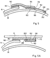
- FIG. 5 shows a variation of the embodiment shown in FIG. 3. It should be noted that in the embodiments shown in FIGS. 3A and 3B, a shaky sticky side of the release adhesive tape 100 remains uncovered after the connection. Although this uncovered side usually does not cause any problems, the embodiment shown in FIG. 5 provides that this uncovered, weakly tacky adhesive side is covered before it is moved on by a printing press.
- the embodiment in FIG. 5 also comprises a carrier strip 160, a holding adhesive tape 170, a connecting adhesive tape 180 and a separating adhesive tape 190.
- the holding adhesive tape 170 and the connecting adhesive tape 180 are both double-sided adhesive tapes with strong adhesive on both sides .
- the Separating adhesive tape 190 has an inner adhesive side 192 with weakly tacky adhesive and an outer adhesive side 194 with highly tacky adhesive.
- the carrier strip 160 has an elongated part 162 which extends beyond the separating adhesive tape 192.
- a cover strip 200 is attached between the end of the elongated portion 162 and the second layer 36.
- the cover strip 200 has an inner adhesive side 202 with a low-tack adhesive and an outer adhesive side 204 with a high-tack adhesive.
- FIG. 5A The effect of the extended portion 162 of the carrier strip 160 and the masking tape 200 is shown in Fig. 5A.
- the running web 8 is connected to the carrier strip 160 by the holding adhesive tape 170, the first layer 16 and the separating adhesive tape 190 are pulled away from the second layer 36 by the connecting adhesive tape 180.
- the masking tape 200 due to the masking tape 200, the end of the extended portion 162 remains in place.
- the running web 8 is pulled forward together with the first layer 16
- the extended part 162 folds under the separating adhesive tape 190 and connects to the inner adhesive side 192 of the adhesive tape 190.
- the cover strip 200 also comes off at the weakly tacky connection, that exists between the cover strip 200 and the second layer 36 with the inner adhesive side 202.
- the inner adhesive side 202 then connects to the underside of the carrier strip 160 as shown in FIG. 5A.
- this embodiment provides that no adhesive surface is uncovered when the new web is moved through the printing press.
- FIG. 6 Another embodiment similar to that shown in FIG. 3 is shown in FIG. 6. This design also avoids that an uncovered adhesive surface is moved by the printing machine. As shown in Fig. 6, this embodiment includes a holding adhesive tape 220, a connecting adhesive tape 240, a separating adhesive tape 250 and a carrier strip 230.
- the holding adhesive tape 220 is only provided at the rear end of the outer surface 234 of the carrier strip 230.
- the holding adhesive tape 220 and the connecting adhesive tape 240 are double-sided adhesive tapes with strongly adhesive adhesive on both sides.
- the separating adhesive tape 250 is provided with a strongly tacky adhesive on its inner adhesive side 252 and with a weakly tacky adhesive on its outer adhesive side 254.
- the arrangement in FIG. 6 further comprises a long cover strip 290 which extends over the front edge 232 of the carrier strip 230.
- the cover strip 290 has a rear edge 292 and a front edge 294.
- a double-sided adhesive tape 260 is provided with an inner adhesive surface 262 and an outer adhesive surface 264.
- the outer adhesive surface 264 is provided with a highly tacky adhesive and is connected to the inner surface 296 of the cover strip 290 close to the rear edge 292 thereof.
- the inner adhesive surface 262 is provided with a slightly tacky adhesive and forms a weak connection to the outer surface 234 of the carrier strip 230.
- a long strip of pressure-sensitive adhesive tape 270 is also provided between the cover strip 290 and the carrier strip 230.
- the pressure-sensitive adhesive tape 270 has an inner adhesive side 272 with a high-tack adhesive and an outer adhesive side 274 with a low-tack adhesive.
- the inner adhesive side 272 is bonded to the outer surface 234 of the carrier strip 230 near the leading edge 232.
- the outer adhesive side 274 forms a weak connection with the inner surface 296 of the cover strip 290.
- a long strip of double-sided security adhesive tape 280 with an inner adhesive side 282 and an outer adhesive side 284 is also provided. Both sides 282 and 284 are provided with a highly tacky adhesive.
- the security adhesive tape 280 connects the inner surface 296 of the cover strip 290 to the second layer 36, as shown.
- FIG. 6A The effect of arranging the embodiment of FIG. 6 after connection is shown in FIG. 6A.
- the carrier strip 230 and the connecting adhesive tape 240 produce an adhesive connection between the running web 8 and the holding adhesive tape 220, which pulls the first layer 16 forward. If the adhesive tape 220 and the carrier strip 230 are pulled forward, then the weak connections with the inner adhesive side 262 of the release adhesive tape 260, the outer adhesive side 274 of the pressure-sensitive adhesive tape 270 and the outer adhesive side 254 of the release adhesive tape 250 are broken.
- the breaking of these weak connections allows the cover strip 290 to fall back and cover the release tape 250, as shown in FIG. 6A.
- the breaking of these weak connections also allows the pressure sensitive adhesive tape 270 to swing up and make an adhesive connection with the running web 8, as shown. This entire process ensures that no uncovered adhesive surfaces are moved through the printing press.
- all the carrier strips and double-sided adhesive tapes provided in the designs according to FIGS. 3, 4, 5 and 6 extend over the entire width of the new web roll 10, which is identified by the reference number 54.
- a gap 56 may be provided for an adhesive-free area where a belt drive can accelerate the new web roll 10 during the start-up rotation.
- it may be that to create an adhesive-free drive area only the uncovered double-sided adhesive tape shown in FIGS. 3, 4, 5 and 6 is provided with a gap, while the other adhesive tapes and the carrier strip extend over the entire width of the new web roll 10.
Landscapes
- Chemical & Material Sciences (AREA)
- Organic Chemistry (AREA)
- Replacement Of Web Rolls (AREA)
Applications Claiming Priority (2)
| Application Number | Priority Date | Filing Date | Title |
|---|---|---|---|
| US635693A | 1993-01-19 | 1993-01-19 | |
| US6356 | 1993-01-19 |
Publications (2)
| Publication Number | Publication Date |
|---|---|
| EP0618162A2 true EP0618162A2 (fr) | 1994-10-05 |
| EP0618162A3 EP0618162A3 (fr) | 1995-01-11 |
Family
ID=21720495
Family Applications (1)
| Application Number | Title | Priority Date | Filing Date |
|---|---|---|---|
| EP93118741A Withdrawn EP0618162A3 (fr) | 1993-01-19 | 1993-11-22 | Ruban adhésif de raccordement de bande pour une bobine nouvelle. |
Country Status (2)
| Country | Link |
|---|---|
| EP (1) | EP0618162A3 (fr) |
| DE (1) | DE4339309A1 (fr) |
Cited By (3)
| Publication number | Priority date | Publication date | Assignee | Title |
|---|---|---|---|---|
| DE29621879U1 (de) * | 1996-12-17 | 1997-02-27 | Voith Sulzer Papiermaschinen GmbH, 89522 Heidenheim | Anordnung von Klebeschichten einer Splice-Stelle |
| EP0970904A1 (fr) * | 1998-07-09 | 2000-01-12 | Beiersdorf Aktiengesellschaft | Bande adhésive et son utilisation |
| CN103465523A (zh) * | 2013-09-18 | 2013-12-25 | 金东纸业(江苏)股份有限公司 | 具有飞接接头的卷材及其制作方法 |
Families Citing this family (5)
| Publication number | Priority date | Publication date | Assignee | Title |
|---|---|---|---|---|
| DE4413663A1 (de) * | 1994-04-20 | 1995-10-26 | Wifag Maschf | Klebemittel zum Verbinden von auf angetriebenen Rollen gewickelten Materialbahnen |
| DE29500653U1 (de) * | 1995-01-17 | 1995-03-30 | Alex Breuer GmbH, 50667 Köln | Verklebte Papierbahnen |
| DE10118362B4 (de) | 2001-04-12 | 2006-07-27 | Koenig & Bauer Ag | Verfahren zur Verbindung eines Bahnanfanges einer Materialrolle |
| DE102015214193A1 (de) * | 2015-07-27 | 2017-02-02 | Tesa Se | Klebeband für den fliegenden Rollenwechsel |
| DE102017121670A1 (de) * | 2017-09-19 | 2019-03-21 | Krones Aktiengesellschaft | Vorratsrolle mit Haftmarkierung und Verfahren zum Umgang mit Flach- und/oder Bandmaterial |
Family Cites Families (8)
| Publication number | Priority date | Publication date | Assignee | Title |
|---|---|---|---|---|
| GB481866A (en) * | 1936-09-16 | 1938-03-16 | Hoe & Co R | Method of and means for preparing a web roll for use in web renewing mechanism for printing machines |
| US2377971A (en) * | 1943-12-15 | 1945-06-12 | Wood Newspaper Mach Corp | Means for use in splicing webs |
| GB915287A (en) * | 1958-05-23 | 1963-01-09 | Hoe & Co R | An improved adhesive tab |
| GB1216283A (en) * | 1968-05-17 | 1970-12-16 | Dennison Mfg Co | Paster tabs |
| SE466346B (sv) * | 1989-12-01 | 1992-02-03 | Jan Olof Norrman | Saett att skarva en loepande materialbana med ett vidhaeftningselement |
| US5323981A (en) * | 1991-12-13 | 1994-06-28 | Sequa Corporation | Splicer tape system |
| DE9201286U1 (de) * | 1992-02-03 | 1992-05-07 | Bosse, Rolf, Dr.-Ing., 8011 Grasbrunn | Fliegender Rollenkleber |
| DE4210329A1 (de) * | 1992-03-30 | 1993-10-07 | Koenig & Bauer Ag | Anordnung zum Verbinden aufeinanderfolgender, zu Rollen gewickelter Papierbahnen |
-
1993
- 1993-11-18 DE DE4339309A patent/DE4339309A1/de not_active Withdrawn
- 1993-11-22 EP EP93118741A patent/EP0618162A3/fr not_active Withdrawn
Cited By (5)
| Publication number | Priority date | Publication date | Assignee | Title |
|---|---|---|---|---|
| DE29621879U1 (de) * | 1996-12-17 | 1997-02-27 | Voith Sulzer Papiermaschinen GmbH, 89522 Heidenheim | Anordnung von Klebeschichten einer Splice-Stelle |
| EP0970904A1 (fr) * | 1998-07-09 | 2000-01-12 | Beiersdorf Aktiengesellschaft | Bande adhésive et son utilisation |
| US6637697B1 (en) | 1998-07-09 | 2003-10-28 | Tesa Ag | Adhesive tape and its use |
| CN103465523A (zh) * | 2013-09-18 | 2013-12-25 | 金东纸业(江苏)股份有限公司 | 具有飞接接头的卷材及其制作方法 |
| CN103465523B (zh) * | 2013-09-18 | 2015-12-09 | 金东纸业(江苏)股份有限公司 | 具有飞接接头的卷材及其制作方法 |
Also Published As
| Publication number | Publication date |
|---|---|
| DE4339309A1 (de) | 1994-07-21 |
| EP0618162A3 (fr) | 1995-01-11 |
Similar Documents
| Publication | Publication Date | Title |
|---|---|---|
| DE69407822T2 (de) | Verbindungsklebeband, verfahren zum verbinden und spleiss mit dem verbindungsklebeband | |
| EP0970904B1 (fr) | Bande adhésive et son utilisation | |
| EP0970905B1 (fr) | Bande adhésive et son utilisation | |
| EP0818408B1 (fr) | Ruban adhésif et procédé pour sa production | |
| EP0831046B1 (fr) | Bande adhésive double face pour rattacher une bande de papier et procédé pour son utilisation | |
| DE69405861T2 (de) | Spleissband, spleissungsverfahren und ein spleiss der dieses band verwendet | |
| EP0450312B1 (fr) | Procédé pour épisser le début d'une bande enroulée avec la fin d'une autre bande enroulée. | |
| DE2807460C2 (de) | Windelverschlußstreifen | |
| EP1423322B1 (fr) | Bande adhesive detectable par machine | |
| EP0566880A1 (fr) | Dispositif pour raccorder des bandes successives de papier enroulées en bobines | |
| EP1432631B1 (fr) | Bande adhesive detectable par machine | |
| DE19841609A1 (de) | Haftelement oder -streifen für Fliegenden Rollenwechsel | |
| EP1258441B1 (fr) | Bande adhésive | |
| EP1423321B1 (fr) | Bande adhesive detectable par machine | |
| DE4339309A1 (de) | Bahnverbindungsklebeband für eine neue Bahnrolle | |
| EP1640301B1 (fr) | Ruban adhésif pour la réalisation d'un raccordement à la volée avec un système clivable pendant le changement d'un rouleau. | |
| EP1630116B1 (fr) | Ruban adhésif pour joint de raccordement | |
| DE4233521A1 (de) | Klebeband und seine Verwendung zum Verbinden von Papier- oder Kartonbahnen | |
| EP1604927A1 (fr) | Bande adhésive et son utilisation | |
| EP1340703B1 (fr) | Procédé de fabrication d'un rouleau de bande plate | |
| EP1432632B1 (fr) | Bande de protection | |
| EP3719092B1 (fr) | Bande adhésive et matériau en bande continu plate doté d'une telle bande adhésive | |
| DE2438412A1 (de) | Wegwerfwindel | |
| DE4431222C2 (de) | Spitzenetikett für fliegenden Rollenwechsel | |
| DE8801163U1 (de) | Satz von Etiketten zum automatischen Rollenwechsel |
Legal Events
| Date | Code | Title | Description |
|---|---|---|---|
| PUAI | Public reference made under article 153(3) epc to a published international application that has entered the european phase |
Free format text: ORIGINAL CODE: 0009012 |
|
| 17P | Request for examination filed |
Effective date: 19931122 |
|
| AK | Designated contracting states |
Kind code of ref document: A2 Designated state(s): CH DE FR GB LI |
|
| PUAL | Search report despatched |
Free format text: ORIGINAL CODE: 0009013 |
|
| AK | Designated contracting states |
Kind code of ref document: A3 Designated state(s): CH DE FR GB LI |
|
| GBC | Gb: translation of claims filed (gb section 78(7)/1977) | ||
| STAA | Information on the status of an ep patent application or granted ep patent |
Free format text: STATUS: THE APPLICATION HAS BEEN WITHDRAWN |
|
| 18W | Application withdrawn |
Withdrawal date: 19951116 |