EP0618322B1 - Bausatz zum kippsicheren Verbinden zweier übereinandergesetzter Haushaltmaschinen - Google Patents
Bausatz zum kippsicheren Verbinden zweier übereinandergesetzter Haushaltmaschinen Download PDFInfo
- Publication number
- EP0618322B1 EP0618322B1 EP94100526A EP94100526A EP0618322B1 EP 0618322 B1 EP0618322 B1 EP 0618322B1 EP 94100526 A EP94100526 A EP 94100526A EP 94100526 A EP94100526 A EP 94100526A EP 0618322 B1 EP0618322 B1 EP 0618322B1
- Authority
- EP
- European Patent Office
- Prior art keywords
- machine
- worktop
- surmounted
- screws
- screw holes
- Prior art date
- Legal status (The legal status is an assumption and is not a legal conclusion. Google has not performed a legal analysis and makes no representation as to the accuracy of the status listed.)
- Expired - Lifetime
Links
- 238000005406 washing Methods 0.000 claims description 12
- 238000010079 rubber tapping Methods 0.000 claims description 10
- 238000010276 construction Methods 0.000 claims description 7
- 239000011093 chipboard Substances 0.000 claims description 4
- 239000002184 metal Substances 0.000 claims description 4
- 230000014759 maintenance of location Effects 0.000 claims 4
- 238000001035 drying Methods 0.000 description 8
- 238000012423 maintenance Methods 0.000 description 7
- 238000009434 installation Methods 0.000 description 3
- 238000000034 method Methods 0.000 description 2
- 230000000149 penetrating effect Effects 0.000 description 2
- 230000000284 resting effect Effects 0.000 description 2
- 239000002689 soil Substances 0.000 description 1
Images
Classifications
-
- D—TEXTILES; PAPER
- D06—TREATMENT OF TEXTILES OR THE LIKE; LAUNDERING; FLEXIBLE MATERIALS NOT OTHERWISE PROVIDED FOR
- D06F—LAUNDERING, DRYING, IRONING, PRESSING OR FOLDING TEXTILE ARTICLES
- D06F29/00—Combinations of a washing machine with other separate apparatus in a common frame or the like, e.g. with rinsing apparatus
-
- D—TEXTILES; PAPER
- D06—TREATMENT OF TEXTILES OR THE LIKE; LAUNDERING; FLEXIBLE MATERIALS NOT OTHERWISE PROVIDED FOR
- D06F—LAUNDERING, DRYING, IRONING, PRESSING OR FOLDING TEXTILE ARTICLES
- D06F39/00—Details of washing machines not specific to a single type of machines covered by groups D06F9/00 - D06F27/00
- D06F39/12—Casings; Tubs
Definitions
- the invention is based on a kit for the tilt-proof connection of two superimposed ones Household machines, especially a washing and drying machine a washer-dryer column, of which the machine below is a worktop and the attached machine has a housing jacket and four feet with threaded shafts and has base plates which can be screwed into a base plate for the purpose of height adjustment are.
- Such a device is known from DE 38 27 790 A1. Because of the weight ratios of the two machines and because of the stronger vibrations, the Washing machine can be the machine below, while the drying machine as a patch Machine is mounted above it. This also results in a relatively simple manner trained feet for the attached drying machine.
- the well-known connection kit requires front and side panels to cover the by the peculiarity of the Kit resulting space between the bottom plate of the dryer and the worktop of the washing machine.
- four Z-shaped angles are required, which are on must be attached to the top of the worktop using a total of eight screws, then the footplates of the feet of the tumble dryer from above can be gripped in a forked manner.
- the high number of parts and the proportionate high assembly costs when erecting such a washer-dryer column both disturb the manufacturer, the distribution as well as the customer.
- DE 91 01 782 U1 is a kit for the tilt-proof connection of stackable ones Household appliances are known, but their construction is predominantly used in refrigerators and freezers can be found. Therefore there are significant deviations in the structures of the soil or top areas of the devices to be connected to each other to those of Washing and drying machines before, so that there are no matching features.
- the invention has for its object in a device of the type mentioned to reduce the amount of individual parts and therefore the assembly effort for the installation a washer-dryer column.
- the aim is to reduce the number of parts at the same time limit the financial outlay for the customer.
- the kit by four unthreaded Single foot plates, which are intended to be exchanged for the feet, one on the rear bottom edge of the attached machine and at the rear top edge the bottom standing machine mountable rear bracket for fixing the attached Machine against lifting off the countertop and one on the front bottom edge of the machine and on the front upper edge of the machine below mountable front bracket contains that to fix the attached machine against Moves towards the front of the machine is marked.
- the kit is standard in the bottom of the dryer to remove the screwed feet, into the threaded holes that have become free use four simple base plates from the kit and some parts for the rear bracket and for the front bracket on the worktop of the one below To be installed on the machine and on the vertical walls of the attached machine. This does not require disassembly of the washing machine worktop or the Tilting or even falling of the drying machine to be put on.
- each single plate has a shaft with latching elements which snap into the threads instead of the screwable feet when inserted into the threaded holes in the base plate.
- latching elements which snap into the threads instead of the screwable feet when inserted into the threaded holes in the base plate.
- a particularly simple assembly ensures the development of the kit according to the invention in that the rear bracket two angular holders with pin holes in the upright leg and with screw holes in the leg resting on the worktop, two pins with coaxial screw holes, two threaded plates as counterparts at the location of the holder under the Worktop and four screws for attaching the holder with the threaded plates to the worktop and two self-tapping screws for attaching the pins to the rear wall of the attached machine at the level of the pin holes.
- This makes it possible to mount the angular brackets near the rear edge of the worktop of the machine below on a section that projects beyond the body of the machine below.
- the horizontal leg is placed on the worktop and fastened by means of two screws through holes previously drilled through the worktop, the screws penetrating into a threaded plate, which serves as a counterpart on the underside of the worktop and as a nut replacement.
- Two pegs are mounted at the points of the rear wall of the tumble dryer that overlap the upright legs of the angular holder with the peg holes. For this purpose, they have a coaxial screw hole, which is penetrated by a self-tapping screw penetrating into the rear wall of the tumble dryer.
- the location of the attachment of the pins can be selected in advance so that screws screwed into the rear wall anyway are removed from the rear wall before mounting the pins and using the pins in the same holes are screwed in again.
- the screws of the kit for fastening the pins therefore simultaneously serve to fix the rear wall to the body of the drying machine without using the other parts of the kit.
- the front bracket has a front angle with at least two each Screw holes in each leg and at least two chipboard screws for Attach the bracket to the worktop and at least two self-tapping Screws for fastening the upright angle leg to the front of the Contains the body of the attached machine.
- After measuring the installation site for the Front angle can be directly on the worktop of the machine below can be attached using two or three self-tapping screws.
- the drying machine with the maintenance flap removed - the front is now of the body in the future assembly area - put on the worktop and the Upright angle leg using two self-tapping screws on the Screwed on the front of the body.
- the maintenance flap attached afterwards is covered the front angle.
- kit according to the invention could be the template with two drawing fields equip the after applying the template to the Rear wall the location of the screw holes for mounting the Pin on the attached machine and after creating the Template on the front of the carcass the position of the screw holes to attach the upright leg of the Designate front angle.
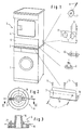
- the washing machine 1 below has a worktop 2, which is assembled by the manufacturer and because of the accessible below electrically conductive components of the washing machine should not be removed.
- the tumble dryer 3 has a body 4 and one in the lower body area Maintenance flap on the front 5. To mount the The tumble dryer on the washing machine first becomes the maintenance hatch 5 hung from her hinge.
- the kit contains several in Figure 1 to the right of the washer-dryer column illustrated items.
- This is four Single foot plates 6, only one of which is shown here is, two pins 7, each with a screw 8, of which here also only one is shown as a device to fix the rear edge of the floor two angular brackets 9, of which only one is also shown here, two threaded plates 10, of which only one here is shown, and a front angle 11 as an arrangement for fixing the front edge of the floor.
- the angular holder 9 has two pin holes 12, one of which the right mortise for the right rear on the worktop mounted bracket and the left mortise for uses the holder mounted on the worktop on the left rear becomes.
- the body of the washing machine 1 protrudes beyond the rear Worktop serve two screws 13 that hold the worktop penetrate and underneath the worktop Threaded hole of the threaded plate 10 are screwed.
- the Threaded plate 10 distributes the tightening forces of the screws large area on the lower surface of the worktop.
- angle 11 contains directly three screw holes on the work surface, which are penetrated by chipboard screws 14.
- the leg 15 resting on the worktop will be later covered by the attached drying machine.
- the upright standing leg 16 of the front angle 11 sits in front of the front of the body 4 of the dryer in the retracted Area of the body behind the later reattached Maintenance flap 5.
- the leg 16 is thread-tapping Screws 17 or self-tapping screws on the Front of the body 4 attached.
- the simple foot plates 6 are shown in more detail in FIGS. 2 and 3.
- Each footplate includes a shaft 18 that the Core diameter of the in the base plate of the dryer arranged threaded hole is adapted.
- the illustrated Example consists of the base plate 19 (shown in broken lines) the dryer 3 from only one out of the sheet the turn for the screw-in thread the feet.
- One on the outer surface of the pin 18 arranged latch 20 engages directly behind the Sheet metal edge of this thread.
- Another one, in the foot area of the pin 18 rooting catch 21 does not engage in one Detail between the beginning and end of the a thread.
- the simple base plate 6 is thus sufficient fixed and can because of the resilient locking lug 21st can also be easily removed from the threaded hole. This simple fixation is sufficient for the footplate during the assembly process until the tumble dryer is put on not on the worktop of the washing machine can fall out.
- the washer is in the intended place set up and his countertop 2 by adjusting the Bring washer feet (not shown) into balance.
- the mounting holes for the two holders provided at the rear 9 and the front angle 11 marked on the worktop 2.
- For each holder 9 are in the worktop two through holes drilled.
- the holder 9 are with the Screws 13 and the threaded plate 10 on the worktop attached.
- the front angle 11 is used of the three chipboard screws 14 at the marked positions attached to the worktop.
- the dryer is lowered onto the worktop at the front and its body front with the leg upright 16 of the front angle connected by means of the screws 17. Then the maintenance flap 5 can be put back into the hinges be hung and closed. The assembly process is ended with that.
Landscapes
- Textile Engineering (AREA)
- Engineering & Computer Science (AREA)
- Main Body Construction Of Washing Machines And Laundry Dryers (AREA)
- Drying Of Solid Materials (AREA)
- Centrifugal Separators (AREA)
- Buildings Adapted To Withstand Abnormal External Influences (AREA)
- Accessory Of Washing/Drying Machine, Commercial Washing/Drying Machine, Other Washing/Drying Machine (AREA)
- Floor Finish (AREA)
- Emergency Lowering Means (AREA)
- Detail Structures Of Washing Machines And Dryers (AREA)
- Apparatus For Making Beverages (AREA)
- Dowels (AREA)
- Catching Or Destruction (AREA)
- Ladders (AREA)
- Handcart (AREA)
- Joints Allowing Movement (AREA)
- Cable Accessories (AREA)
- Vending Machines For Individual Products (AREA)
Description
Eine besonders einfache Montage gewährleistet die Weiterbildung des erfindungsgemäßen Bausatzes dadurch, daß die Rückseitenhalterung zwei winkelförmige Halter mit Zapfenlöchern im aufrecht stehenden Schenkel und mit Schraubenlöchern im auf der Arbeitsplatte anliegenden Schenkel, zwei Zapfen mit koaxialen Schraubenlöchern, zwei Gewindeplatten als Gegenlagen am Ort der Halter unter der Arbeitsplatte sowie vier Schrauben für die Befestigung der Halter mit den Gewindeplatten an der Arbeitsplatte und zwei selbstschneidende Schrauben zum Befestigen der Zapfen an der Rückwand der aufgesetzten Maschine in Höhe der Zapfenlöcher enthält. Dadurch ist es möglich, die winkelförmigen Halter in der Nähe der hinteren Kante der Arbeitsplatte der unten stehenden Maschine an einem Abschnitt zu montieren, der über den Korpus der unten stehenden Maschine hinausragt. Der waagerecht liegende Schenkel wird dabei auf die Arbeitsplatte aufgesetzt und mittels zweier Schrauben durch zuvor durch die Arbeitsplatte gebohrte Löcher hindurch befestigt, wobei die Schrauben in je eine Gewindeplatte eindringen, die als Gegenlage an der Unterseite der Arbeitsplatte und als Mutterersatz dient. An mit den Zapfenlöchern den aufrecht stehenden Schenkel des winkelförmigen Halters sich deckenden Stellen der Rückwand des aufgesetzten Wäschetrockners werden zwei Zapfen montiert. Sie haben dazu ein koaxiales Schraubenloch, das von einer in die Rückwand des Wäschetrockners eindringenden, selbstschneidenden Schraube durchdrungen wird. Wird herstellerseits bereits auf eine Säulen-Montage von Wäschetrocknern über Waschmaschinen Rücksicht genommen, dann kann der Ort der Anbringung der Zapfen vorbereitenderweise so gewählt werden, daß ohnehin in die Rückwand eingeschraubte Schrauben vor dem Montieren der Zapfen aus der Rückwand herausgedreht und unter Verwendung der Zapfen in dieselben Löcher wieder eingedreht werden. Die Schrauben des Bausatzes zur Befestigung der Zapfen dienen daher gleichzeitig ohne Verwendung der übrigen Teile des Bausatzes zur Fixierung der Rückwand am Korpus der Trockenmaschine.
- Fig. 1
- eine Wascher-Trockner-Säule mit den teilweise in Explosionsdarstellung angeordneten Teilen für den Verbindungs-Bausatz gemäß der Erfindung,
- Fig. 2
- eine Draufsicht und
- Fig. 3
- einen Schnitt entlang der Schnittlinie III-III in Figur 2 für eine erfindungsgemäße Einfach-Fußplatte.
Claims (6)
- Bausatz zum kippsicheren Verbinden zweier übereinandergesetzter Haushaltmaschinen (1, 3), insbesondere einer Wasch- und einer Trockenmaschine zu einer Wascher-Trockner-Säule, von denen die unten stehende Maschine (1) eine Arbeitsplatte (2) und die aufgesetzte Maschine (3) einen Gehäusemantel (4) und vier Standfüße mit Gewindeschäften und Fußplatten aufweist, die in eine Bodenplatte zum Zwecke der Höhenjustage einschraubbar sind, dadurch gekennzeichnet, daß er vier gewindelose Einfach-Fußplatten (6), die zum Austausch gegen die Standfüße vorgesehen sind, eine an der hinteren Bodenkante der aufgesetzten Maschine und an der hinteren Oberkante der unten stehenden Maschine montierbare Rückseitenhalterung (7 bis 10, 12, 13) zum Fixieren der aufgesetzten Maschine (3) gegen Abheben von der Arbeitsplatte (2) und eine an der vorderen Bodenkante der aufgesetzten Maschine und an der vorderen Oberkante der unten stehenden Maschine montierbare Frontseitenhalterung (11, 14 bis 17) enthält, die zum Fixieren der aufgesetzten Maschine (3) gegen Bewegungen in Richtung der Frontseite der Maschinen (1, 3) dient.
- Bausatz nach Anspruch 1, dadurch gekennzeichnet, daß jede Einfach-Fußplatte (6) einen Schaft (18) mit Rastelementen (20, 21) aufweist, die beim Einführen in die Gewindelöcher der Bodenplatte anstelle der schraubbaren Standfüße in einen Gewindegang einrasten.
- Bausatz nach Anspruch 1 oder 2, dadurch gekennzeichnet, daß die Rückseitenhalterung zwei winkelförmige Halter (9) mit Zapfenlöchern (12) im aufrecht stehenden Schenkel und mit Schraubenlöchern im auf der Arbeitsplatte (2) anliegenden Schenkel, zwei Zapfen (7) mit koaxialen Schraubenlöchern, zwei Gewindeplatten (10) als Gegenlagen am Ort der Halter (9) unter der Arbeitsplatte (2) sowie vier Schrauben (13) für die Befestigung der Halter (9) mit den Gewindeplatten (10) an der Arbeitsplatte (2) und zwei gewindefurchende Schrauben (8) oder Blechschrauben zum Befestigen der Zapfen (7) an der Rückwand der aufgesetzten Maschine (3) in Höhe der Zapfenlöcher (12) enthält.
- Bausatz nach einem der Ansprüche 1 bis 3, dadurch gekennzeichnet, daß die Frontseitenhalterung einen Frontseiten-Winkel (11) mit mindestens zwei Schraubenlöchern in jedem Schenkel (15, 16) sowie mindestens zwei Spanplattenschrauben (14) zum Befestigen des Winkels (11) auf der Arbeitsplatte (2) und mindestens zwei gewindefurchende Schrauben (17) oder Blechschrauben zum Befestigen des aufrecht stehenden Winkel-Schenkels (16) an der Frontseite des Korpus (4) der aufgesetzten Maschine (3) enthält.
- Bausatz nach Anspruch 4, dadurch gekennzeichnet, daß eine an die Größe der Arbeitsplatte (2) angepaßte Schablone vorgesehen ist, die die genaue Lage der Schraubenlöcher für die Montage der Einrichtung (7 bis 10, 12, 13) und der Anordnung (11, 14 bis 17) an der Arbeitsplatte (2) bezeichnet.
- Bausatz nach Anspruch 5, dadurch gekennzeichnet, daß die Schablone zwei Zeichnungsfelder aufweist, die nach Anlegen der Schablone an die Rückwand die Lage der Schraubenlöcher für die Montage der Zapfen (7) an der aufgesetzten Maschine (3) und nach Anlegen der Schablone an der Korpus-Frontseite die Lage der Schraubenlöcher zum Befestigen des aufrechtstehenden Schenkels (16) des Frontseiten-Winkels (11) bezeichnen.
Applications Claiming Priority (2)
| Application Number | Priority Date | Filing Date | Title |
|---|---|---|---|
| DE4310236 | 1993-03-30 | ||
| DE4310236A DE4310236A1 (de) | 1993-03-30 | 1993-03-30 | Bausatz zum kippsicheren Verbinden zweier übereinandergesetzter Haushaltmaschinen |
Publications (2)
| Publication Number | Publication Date |
|---|---|
| EP0618322A1 EP0618322A1 (de) | 1994-10-05 |
| EP0618322B1 true EP0618322B1 (de) | 1999-11-24 |
Family
ID=6484177
Family Applications (1)
| Application Number | Title | Priority Date | Filing Date |
|---|---|---|---|
| EP94100526A Expired - Lifetime EP0618322B1 (de) | 1993-03-30 | 1994-01-14 | Bausatz zum kippsicheren Verbinden zweier übereinandergesetzter Haushaltmaschinen |
Country Status (6)
| Country | Link |
|---|---|
| EP (1) | EP0618322B1 (de) |
| AT (1) | ATE186958T1 (de) |
| DE (2) | DE4310236A1 (de) |
| DK (1) | DK0618322T3 (de) |
| FI (1) | FI104742B (de) |
| NO (1) | NO179416C (de) |
Cited By (1)
| Publication number | Priority date | Publication date | Assignee | Title |
|---|---|---|---|---|
| US12577722B2 (en) | 2024-05-16 | 2026-03-17 | Haier Us Appliance Solutions, Inc. | Stacking mount assembly for mounting a pair of laundry appliances |
Families Citing this family (7)
| Publication number | Priority date | Publication date | Assignee | Title |
|---|---|---|---|---|
| DE19905742B4 (de) * | 1999-02-11 | 2010-01-07 | BSH Bosch und Siemens Hausgeräte GmbH | Bausatz von mindestens zwei miteinander aufzustellenden, programmgesteuerten Haushaltgeräten |
| US7685846B2 (en) * | 2003-12-29 | 2010-03-30 | Lg Electronics Inc. | Assembly for stacking washers and dryers |
| KR100799994B1 (ko) | 2003-12-29 | 2008-01-31 | 엘지전자 주식회사 | 드럼타입 세탁/건조장치의 적층킷트 |
| KR20060005849A (ko) | 2004-07-14 | 2006-01-18 | 삼성전자주식회사 | 상하체결구조를 갖는 가전제품 및 그 체결방법 |
| KR101263862B1 (ko) | 2005-05-23 | 2013-05-13 | 엘지전자 주식회사 | 세정 장치 |
| AU2007288668B2 (en) | 2006-08-23 | 2010-09-09 | Lg Electronics Inc. | Multiple laundry treating machine |
| CN112391790A (zh) * | 2020-11-28 | 2021-02-23 | 珠海格力电器股份有限公司 | 一种多桶洗衣机的桶间连接结构及具有其的多桶洗衣机 |
Family Cites Families (2)
| Publication number | Priority date | Publication date | Assignee | Title |
|---|---|---|---|---|
| DE3827790A1 (de) * | 1988-08-16 | 1990-02-22 | Bosch Siemens Hausgeraete | Bausatz zum kippsicheren verbinden zweier uebereinandergesetzter haushaltmaschinen |
| DE9101782U1 (de) * | 1991-02-15 | 1991-05-08 | Bosch-Siemens Hausgeräte GmbH, 8000 München | Bausatz zum kippsicheren Verbinden von aufeinandertürmbaren Hausgeräten |
-
1993
- 1993-03-30 DE DE4310236A patent/DE4310236A1/de not_active Withdrawn
-
1994
- 1994-01-14 AT AT94100526T patent/ATE186958T1/de not_active IP Right Cessation
- 1994-01-14 DE DE59408943T patent/DE59408943D1/de not_active Expired - Fee Related
- 1994-01-14 EP EP94100526A patent/EP0618322B1/de not_active Expired - Lifetime
- 1994-01-14 DK DK94100526T patent/DK0618322T3/da active
- 1994-03-29 NO NO941170A patent/NO179416C/no not_active IP Right Cessation
- 1994-03-30 FI FI941481A patent/FI104742B/fi active
Cited By (1)
| Publication number | Priority date | Publication date | Assignee | Title |
|---|---|---|---|---|
| US12577722B2 (en) | 2024-05-16 | 2026-03-17 | Haier Us Appliance Solutions, Inc. | Stacking mount assembly for mounting a pair of laundry appliances |
Also Published As
| Publication number | Publication date |
|---|---|
| EP0618322A1 (de) | 1994-10-05 |
| FI941481A7 (fi) | 1994-10-01 |
| NO179416B (no) | 1996-06-24 |
| DK0618322T3 (da) | 2000-05-22 |
| ATE186958T1 (de) | 1999-12-15 |
| DE4310236A1 (de) | 1994-10-06 |
| FI104742B (fi) | 2000-03-31 |
| FI941481A0 (fi) | 1994-03-30 |
| NO941170L (no) | 1994-10-03 |
| NO179416C (no) | 1996-10-02 |
| DE59408943D1 (de) | 1999-12-30 |
| NO941170D0 (no) | 1994-03-29 |
Similar Documents
| Publication | Publication Date | Title |
|---|---|---|
| DE3827790C2 (de) | ||
| EP0939985B1 (de) | Bausatz für ein rahmengestell mit eckverbindung für die vertikalen rahmenprofile | |
| DE102019102301A1 (de) | Tiermöbelvorrichtung und Verfahren zum Montieren derselben | |
| EP0167833B1 (de) | Schaltschrank mit Montageplatte | |
| DE69020604T2 (de) | Verborgene Vorrichtung zur Wandmontage eines Wandmöbelelementes. | |
| DE69402525T2 (de) | Gerüst mit variabler grösse für elektrische und/oder elektronische anlage | |
| EP0618322B1 (de) | Bausatz zum kippsicheren Verbinden zweier übereinandergesetzter Haushaltmaschinen | |
| DE10393168B4 (de) | Stützgestellstruktur für modulare Büromöbel | |
| DE1901685C3 (de) | Aufhängevorrichtung für einen Wandschrank | |
| DE60205684T2 (de) | Verstellbares Scharnier für Kühlschranktüren | |
| DE3827789A1 (de) | Vorrichtung zum kippsicheren verbinden zweier uebereinandergesetzter haushaltmaschinen | |
| DE8432766U1 (de) | Bausatz für Montagevorrichtungen für elektrische Schalt- oder Verteilerschränke | |
| DE8012428U1 (de) | Vorrichtung zur Einstellung der Ausgleichskraft an der Tür einer Spülmaschine | |
| DE19911625C2 (de) | Bausatz für ein Gehäuse | |
| DE4103842C2 (de) | ||
| DE7319906U (de) | Beschlag zum einstellen und fixieren der frontplatte eines ausziehbaren moebelteiles | |
| DE4233803C2 (de) | Vorrichtung zum kippsicheren Verbinden zweier übereinandergesetzter Haushaltmaschinen | |
| DE10327367A1 (de) | Sockelgestell für ein Haushaltsgerät | |
| DE102015116131B4 (de) | Standfuß mit Winkelausgleich, insbesondere für eine Wägeanordnung, Wägeanordnung und Montageverfahren | |
| DE9111216U1 (de) | Beinaufbau | |
| EP0357861B1 (de) | Schrank | |
| DE3918220A1 (de) | Karusselbodensystem fuer schraenke | |
| DE2941794B1 (de) | Tuerschrank | |
| DE68921212T2 (de) | Geschirrspülmaschine. | |
| DE29907127U1 (de) | Behälter mit mehreren Behälterfüßen |
Legal Events
| Date | Code | Title | Description |
|---|---|---|---|
| PUAI | Public reference made under article 153(3) epc to a published international application that has entered the european phase |
Free format text: ORIGINAL CODE: 0009012 |
|
| AK | Designated contracting states |
Kind code of ref document: A1 Designated state(s): AT DE DK FR GB NL SE |
|
| 17P | Request for examination filed |
Effective date: 19950308 |
|
| 17Q | First examination report despatched |
Effective date: 19951222 |
|
| RAP1 | Party data changed (applicant data changed or rights of an application transferred) |
Owner name: BSH BOSCH UND SIEMENS HAUSGERAETE GMBH |
|
| GRAG | Despatch of communication of intention to grant |
Free format text: ORIGINAL CODE: EPIDOS AGRA |
|
| GRAG | Despatch of communication of intention to grant |
Free format text: ORIGINAL CODE: EPIDOS AGRA |
|
| GRAH | Despatch of communication of intention to grant a patent |
Free format text: ORIGINAL CODE: EPIDOS IGRA |
|
| GRAH | Despatch of communication of intention to grant a patent |
Free format text: ORIGINAL CODE: EPIDOS IGRA |
|
| GRAA | (expected) grant |
Free format text: ORIGINAL CODE: 0009210 |
|
| AK | Designated contracting states |
Kind code of ref document: B1 Designated state(s): AT DE DK FR GB NL SE |
|
| REF | Corresponds to: |
Ref document number: 186958 Country of ref document: AT Date of ref document: 19991215 Kind code of ref document: T |
|
| ET | Fr: translation filed | ||
| GBT | Gb: translation of ep patent filed (gb section 77(6)(a)/1977) |
Effective date: 19991124 |
|
| REF | Corresponds to: |
Ref document number: 59408943 Country of ref document: DE Date of ref document: 19991230 |
|
| REG | Reference to a national code |
Ref country code: DK Ref legal event code: T3 |
|
| PLBE | No opposition filed within time limit |
Free format text: ORIGINAL CODE: 0009261 |
|
| STAA | Information on the status of an ep patent application or granted ep patent |
Free format text: STATUS: NO OPPOSITION FILED WITHIN TIME LIMIT |
|
| 26N | No opposition filed | ||
| REG | Reference to a national code |
Ref country code: GB Ref legal event code: IF02 |
|
| PGFP | Annual fee paid to national office [announced via postgrant information from national office to epo] |
Ref country code: DK Payment date: 20020121 Year of fee payment: 9 |
|
| PGFP | Annual fee paid to national office [announced via postgrant information from national office to epo] |
Ref country code: NL Payment date: 20020124 Year of fee payment: 9 Ref country code: AT Payment date: 20020124 Year of fee payment: 9 |
|
| PG25 | Lapsed in a contracting state [announced via postgrant information from national office to epo] |
Ref country code: AT Free format text: LAPSE BECAUSE OF NON-PAYMENT OF DUE FEES Effective date: 20030114 |
|
| PG25 | Lapsed in a contracting state [announced via postgrant information from national office to epo] |
Ref country code: DK Free format text: LAPSE BECAUSE OF NON-PAYMENT OF DUE FEES Effective date: 20030131 |
|
| PG25 | Lapsed in a contracting state [announced via postgrant information from national office to epo] |
Ref country code: NL Free format text: LAPSE BECAUSE OF NON-PAYMENT OF DUE FEES Effective date: 20030801 |
|
| REG | Reference to a national code |
Ref country code: DK Ref legal event code: EBP |
|
| NLV4 | Nl: lapsed or anulled due to non-payment of the annual fee |
Effective date: 20030801 |
|
| PGFP | Annual fee paid to national office [announced via postgrant information from national office to epo] |
Ref country code: SE Payment date: 20050125 Year of fee payment: 12 |
|
| PG25 | Lapsed in a contracting state [announced via postgrant information from national office to epo] |
Ref country code: SE Free format text: LAPSE BECAUSE OF NON-PAYMENT OF DUE FEES Effective date: 20060115 |
|
| EUG | Se: european patent has lapsed | ||
| PGFP | Annual fee paid to national office [announced via postgrant information from national office to epo] |
Ref country code: DE Payment date: 20090131 Year of fee payment: 16 |
|
| PGFP | Annual fee paid to national office [announced via postgrant information from national office to epo] |
Ref country code: GB Payment date: 20090123 Year of fee payment: 16 |
|
| PGFP | Annual fee paid to national office [announced via postgrant information from national office to epo] |
Ref country code: FR Payment date: 20090120 Year of fee payment: 16 |
|
| GBPC | Gb: european patent ceased through non-payment of renewal fee |
Effective date: 20100114 |
|
| REG | Reference to a national code |
Ref country code: FR Ref legal event code: ST Effective date: 20100930 |
|
| PG25 | Lapsed in a contracting state [announced via postgrant information from national office to epo] |
Ref country code: FR Free format text: LAPSE BECAUSE OF NON-PAYMENT OF DUE FEES Effective date: 20100201 |
|
| PG25 | Lapsed in a contracting state [announced via postgrant information from national office to epo] |
Ref country code: DE Free format text: LAPSE BECAUSE OF NON-PAYMENT OF DUE FEES Effective date: 20100803 |
|
| PG25 | Lapsed in a contracting state [announced via postgrant information from national office to epo] |
Ref country code: GB Free format text: LAPSE BECAUSE OF NON-PAYMENT OF DUE FEES Effective date: 20100114 |