EP0618355B1 - Verfahren und Einrichtung zur Steuerung des Betriebs einer Brennkraftmaschine eines Kraftfahrzeuges - Google Patents
Verfahren und Einrichtung zur Steuerung des Betriebs einer Brennkraftmaschine eines Kraftfahrzeuges Download PDFInfo
- Publication number
- EP0618355B1 EP0618355B1 EP19940400602 EP94400602A EP0618355B1 EP 0618355 B1 EP0618355 B1 EP 0618355B1 EP 19940400602 EP19940400602 EP 19940400602 EP 94400602 A EP94400602 A EP 94400602A EP 0618355 B1 EP0618355 B1 EP 0618355B1
- Authority
- EP
- European Patent Office
- Prior art keywords
- engine
- speed
- controlling
- regulator
- filtered
- Prior art date
- Legal status (The legal status is an assumption and is not a legal conclusion. Google has not performed a legal analysis and makes no representation as to the accuracy of the status listed.)
- Expired - Lifetime
Links
- 238000000034 method Methods 0.000 title claims description 20
- 238000002485 combustion reaction Methods 0.000 title claims description 6
- 230000010355 oscillation Effects 0.000 claims description 23
- 238000005070 sampling Methods 0.000 claims description 17
- 230000005540 biological transmission Effects 0.000 claims description 8
- 230000001133 acceleration Effects 0.000 claims description 6
- 238000012937 correction Methods 0.000 description 31
- 238000012546 transfer Methods 0.000 description 9
- 238000013016 damping Methods 0.000 description 6
- 238000010586 diagram Methods 0.000 description 4
- 230000035945 sensitivity Effects 0.000 description 4
- 238000004364 calculation method Methods 0.000 description 3
- 239000000243 solution Substances 0.000 description 3
- 238000009432 framing Methods 0.000 description 2
- 238000005259 measurement Methods 0.000 description 2
- 230000003068 static effect Effects 0.000 description 2
- 238000004458 analytical method Methods 0.000 description 1
- 230000008094 contradictory effect Effects 0.000 description 1
- 238000007796 conventional method Methods 0.000 description 1
- 239000013256 coordination polymer Substances 0.000 description 1
- 238000001514 detection method Methods 0.000 description 1
- 230000008030 elimination Effects 0.000 description 1
- 238000003379 elimination reaction Methods 0.000 description 1
- 238000005516 engineering process Methods 0.000 description 1
- 238000002347 injection Methods 0.000 description 1
- 239000007924 injection Substances 0.000 description 1
- 238000013507 mapping Methods 0.000 description 1
- 238000012544 monitoring process Methods 0.000 description 1
- 230000000717 retained effect Effects 0.000 description 1
- 230000001360 synchronised effect Effects 0.000 description 1
Images
Classifications
-
- F—MECHANICAL ENGINEERING; LIGHTING; HEATING; WEAPONS; BLASTING
- F02—COMBUSTION ENGINES; HOT-GAS OR COMBUSTION-PRODUCT ENGINE PLANTS
- F02D—CONTROLLING COMBUSTION ENGINES
- F02D41/00—Electrical control of supply of combustible mixture or its constituents
- F02D41/02—Circuit arrangements for generating control signals
- F02D41/14—Introducing closed-loop corrections
- F02D41/1497—With detection of the mechanical response of the engine
- F02D41/1498—With detection of the mechanical response of the engine measuring engine roughness
-
- F—MECHANICAL ENGINEERING; LIGHTING; HEATING; WEAPONS; BLASTING
- F02—COMBUSTION ENGINES; HOT-GAS OR COMBUSTION-PRODUCT ENGINE PLANTS
- F02D—CONTROLLING COMBUSTION ENGINES
- F02D41/00—Electrical control of supply of combustible mixture or its constituents
- F02D41/02—Circuit arrangements for generating control signals
- F02D41/14—Introducing closed-loop corrections
- F02D41/1401—Introducing closed-loop corrections characterised by the control or regulation method
- F02D2041/1413—Controller structures or design
- F02D2041/1432—Controller structures or design the system including a filter, e.g. a low pass or high pass filter
-
- F—MECHANICAL ENGINEERING; LIGHTING; HEATING; WEAPONS; BLASTING
- F02—COMBUSTION ENGINES; HOT-GAS OR COMBUSTION-PRODUCT ENGINE PLANTS
- F02D—CONTROLLING COMBUSTION ENGINES
- F02D2200/00—Input parameters for engine control
- F02D2200/02—Input parameters for engine control the parameters being related to the engine
- F02D2200/10—Parameters related to the engine output, e.g. engine torque or engine speed
- F02D2200/1002—Output torque
- F02D2200/1004—Estimation of the output torque
-
- F—MECHANICAL ENGINEERING; LIGHTING; HEATING; WEAPONS; BLASTING
- F02—COMBUSTION ENGINES; HOT-GAS OR COMBUSTION-PRODUCT ENGINE PLANTS
- F02D—CONTROLLING COMBUSTION ENGINES
- F02D2200/00—Input parameters for engine control
- F02D2200/02—Input parameters for engine control the parameters being related to the engine
- F02D2200/10—Parameters related to the engine output, e.g. engine torque or engine speed
- F02D2200/1015—Engines misfires
-
- F—MECHANICAL ENGINEERING; LIGHTING; HEATING; WEAPONS; BLASTING
- F02—COMBUSTION ENGINES; HOT-GAS OR COMBUSTION-PRODUCT ENGINE PLANTS
- F02D—CONTROLLING COMBUSTION ENGINES
- F02D41/00—Electrical control of supply of combustible mixture or its constituents
- F02D41/0097—Electrical control of supply of combustible mixture or its constituents using means for generating speed signals
Definitions
- the present invention relates to a method and a device for controlling the operation of an internal combustion engine of a motor vehicle, by controlling at least one parameter for controlling the operation of this engine.
- the object of the invention is therefore to solve these problems.
- the subject of the invention is a method for controlling the operation of an internal combustion engine of a motor vehicle, by controlling at least one parameter for controlling the operation of this engine, characterized in that it consists in developing a filtered engine speed signal representative of the engine speed oscillations, and in controlling this filtered engine speed signal to 0, to dampen the engine speed oscillations, by calculating a correction to be made to the engine torque and determining of the corresponding correction to be applied to said engine operating control parameter, using a digital regulator whose parameters have been previously calculated from a motor torque estimator model into which the engine control parameters are introduced operation of the engine and a filtered transmission estimator model for each gearbox report.
- the invention also relates to a device for implementing the method as described above.
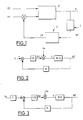
- Fig.1 the engine of a motor vehicle is shown diagrammatically by the block designated by the general reference 1 and receives as input parameters for controlling its operation, designated for example by the references P1 and P2.
- the output of this engine is illustrated by the speed N thereof.
- this regime N is a function of the various parameters P1 and P2 for controlling the operation of this engine.
- the method and the device according to the invention are suitable for damping the longitudinal oscillations of the vehicle generated by the oscillations of the engine speed.
- the method according to the invention consists in developing a filtered engine speed signal NF representative of the oscillations of this speed N and in controlling this filtered engine speed signal to 0, by calculating a correction to be made to the engine torque and determining the corresponding correction to be applied to an engine operation control parameter, using a digital regulator.
- the filtered speed NF representative of the oscillations of the engine speed N is obtained by passing this speed through a filter designated by reference 2 in this figure, while the digital regulator is designated by reference 3, the output correction thereof being designated by the reference CP and being applied for example to the parameter P1 for controlling the operation of the motor.
- the filter 2 can be integrated into the regulator 3.
- control parameter is for example the ignition advance.
- correction can also be applied to other parameters for controlling the operation of the engine as will be described in more detail below.
- the parameters of the digital regulator have been calculated beforehand from a model estimating the engine torque into which are introduced the parameters for controlling the operation of the engine and a filtered transmission estimator model for each gearbox report. .
- the identification of the filtered transmission estimator model is carried out on the basis of the average engine torque over each constant sampling period of the regulator and of a filtered engine speed obtained from an engine speed interpolated linearly between values of speed measured at two determined angular references of the engine, framing the sampling instant.
- the first phase of identification of this model is a phase of analysis of the functioning of the vehicle engine.
- This vehicle is equipped with an ignition and injection control computer which does not make any corrections to the parameters controlling its operation.
- the working period that is to say the sampling period, being constant, there is no synchronization between the determined angular references and the sampling instants.
- the filtered regime is then obtained from this interpolated regime by passing through a high-pass filter of order at least equal to two to eliminate both a continuous component and a constant variation so as not to correct the system during constant acceleration without oscillation.
- Software can be used to identify the model from this information.
- the sampling period is chosen to have a number of samples per period greater than four and to be greater than the short duration of an engine cycle.
- the regulator can be constituted by a regulator with a structure known as RST of which one will find a detailed description in the document mentioned above.
- This regulator is used to dampen the engine speed oscillations by slaving the filtered engine speed signal to 0, as illustrated in Fig.2.
- U 0 represents the contribution of torque due to the driver of the vehicle, that is to say the disturbance.
- the filtered transmission estimator model is represented by a discrete transfer function B / A where B and A are polynomials determined as indicated above.
- the R and S parameters of the regulator are also polynomials.
- the damping and the natural frequencies of the system are determined by the denominator AS + BR.
- the ideal polynomial P can be obtained by modifying the polynomial A insofar as it is not necessary to modify the oscillation frequencies or the damping of the high frequencies.
- the polynomial A can then be decomposed in the form of first and second order polynomials so as to show frequencies and dampings and the damping corresponding to the frequency to be damped is then increased to obtain a modified polynomial which can be used as polynomial P.
- the regulator shown in FIG. 2 makes it possible to quickly dampen an oscillation of the vehicle, but does not make it possible to completely control the acceleration and in particular the amplitude of the first oscillation.
- T has for root at least the value 1, zero static gain.
- This regulator then makes it possible to determine a correction to be made to one of the parameters for controlling the operation of the engine in order to obtain a torque correction and therefore a damping of the oscillations of the vehicle and a control of the pace of the acceleration of the latter. this.
- the correction applied during a sampling period is either the correction applied to the last angular reference determined, before the next sampling period, or the average of the corrections applied to each angular reference determined during the sampling period, ie the average of the corrections applied to each angular reference determined during the sampling period, weighted by the time of application of each correction.
- the method and the device according to the invention uses a correction based on an identified model relating the engine torque to the filtered speed. and calculated at a fixed period, applied to specific angular references.
- the regulator does not have a triggering threshold and it is possible to control the rate of acceleration of the vehicle and to determine a good compromise in vehicle comfort of use.
Landscapes
- Engineering & Computer Science (AREA)
- Chemical & Material Sciences (AREA)
- Combustion & Propulsion (AREA)
- Mechanical Engineering (AREA)
- General Engineering & Computer Science (AREA)
- Combined Controls Of Internal Combustion Engines (AREA)
- Control Of Vehicle Engines Or Engines For Specific Uses (AREA)
- Electrical Control Of Air Or Fuel Supplied To Internal-Combustion Engine (AREA)
Claims (6)
- Verfahren zur Kontrolle der Funktionsweise eines Verbrennungsmotors eines Kraftfahrzeugs durch Steuerung von mindestens einem Kontrollparameter (P1) der Funktionsweise dieses Motors (1),
dadurch gekennzeichnet, daß es darin besteht, ein gefiltertes Motordrehzahlsignal (NF) zu erzeugen, das für die Schwingungen der Motordrehzahl (N) repräsentativ ist, und dieses gefilterte Motordrehzahlsignal auf 0 zu steuern, um die Schwingungen der Motordrehzahl zu dämpfen durch Berechnung einer an dem Motordrehmoment vorzunehmenden Korrektur und Bestimmung der entsprechenden Korrektur (CP), die auf den Kontrollparameter der Funktionsweise des Motors anzuwenden ist mithilfe eines digitalen Reglers, dessen Parameter im voraus berechnet worden sind ausgehend von einem Schätzfunktionsmodell des Motordrehmoments, in das die Kontrollparameter der Funktionsweise des Motors eingegeben sind, und einem Schätzfunktionsmodell der gefilterten Übertragung für jeden Gang des Getriebes. - Verfahren nach Anspruch 1,
dadurch gekennzeichnet, daß dieser digitale Regler (3) ein Regler mit RST-Struktur ist, der ein Optimalwertsteuerungssignal empfängt, das ausgehend von dem Motordrehmoment (Uo) erzeugt wird, um den Verlauf der Beschleunigung des Fahrzeugs zu kontrollieren. - Verfahren nach Anspruch 1 oder 2,
dadurch gekennzeichnet, daß der Regler eine konstante Probenahmeperiode aufweist. - Verfahren nach Anspruch 3,
dadurch gekennzeichnet, daß die Identifizierung des Schätzfunktionsmodells (B/A) der gefilterten Übertragung ausgeführt wird ausgehend von dem mittleren Motordrehmoment für jede Probenahmeperiode des Reglers und einer gefilterten Drehzahl, die ausgehend von einer Drehzahl des Motors erhalten wird, die zwischen bei zwei bestimmten Winkelbezugspunkten gemessenen Drehzahlwerten linear interpoliert wird, wobei der Probenahmezeitpunkt eingeschlossen ist. - Verfahren nach Anspruch 4,
dadurch gekennzeichnet, daß die gefilterte Drehzahl durch den Übergang der interpolierten Drehzahl in einen Hochpaßfilter mindestens zweiter Ordnung erhalten wird. - Vorrichtung zur Kontrolle der Funktionsweise eines Verbrennungsmotors eines Kraftfahrzeugs zur Durchführung des Verfahrens nach einem der vorangehenden Ansprüche, mit Steuermitteln für mindestens einen Kontrollparameter (P1) der Funktionsweise dieses Motors (1),
dadurch gekennzeichnet, daß sie Mittel(2) aufweist zur Erzeugung eines gefilterten Motordrehzahlsignals, das für die Schwingungen der Motordrehzahl (N) repräsentativ ist, und einen Regler (3) zur Steuerung dieses gefilterten Motordrehzahlsignals auf Null, wobei dieser Regler Berechnungsmittel aufweist für eine am Motordrehmoment vorzunehmende Korrektur und eine Bestimmung der entsprechenden Korrektur (CP), die an dem Kontrollparameter der Funktionsweise des Motors vorzunehmen ist, wobei für jeden Gang des Getriebes die Parameter des Reglers ausgehend von einem Schätzfunktionsmodell der Motordrehzahl, in das die Kontrollparameter der Funktionsweise des Motors eingehen, und einem Schätzfunktionsmodells der gefilterten Übertragung im voraus berechnet werden.
Applications Claiming Priority (2)
| Application Number | Priority Date | Filing Date | Title |
|---|---|---|---|
| FR9303605 | 1993-03-29 | ||
| FR9303605A FR2703404B1 (fr) | 1993-03-29 | 1993-03-29 | Procede et dispositif de controle du fonctionnement d'un moteur a combustion interne d'un vehicule automobile . |
Publications (2)
| Publication Number | Publication Date |
|---|---|
| EP0618355A1 EP0618355A1 (de) | 1994-10-05 |
| EP0618355B1 true EP0618355B1 (de) | 1996-12-27 |
Family
ID=9445460
Family Applications (1)
| Application Number | Title | Priority Date | Filing Date |
|---|---|---|---|
| EP19940400602 Expired - Lifetime EP0618355B1 (de) | 1993-03-29 | 1994-03-18 | Verfahren und Einrichtung zur Steuerung des Betriebs einer Brennkraftmaschine eines Kraftfahrzeuges |
Country Status (3)
| Country | Link |
|---|---|
| EP (1) | EP0618355B1 (de) |
| DE (1) | DE69401229T2 (de) |
| FR (1) | FR2703404B1 (de) |
Families Citing this family (2)
| Publication number | Priority date | Publication date | Assignee | Title |
|---|---|---|---|---|
| FR2945079A1 (fr) * | 2009-04-29 | 2010-11-05 | Peugeot Citroen Automobiles Sa | Procede de controle du fonctionnement d'un moteur |
| CN111946470B (zh) * | 2020-07-31 | 2021-11-23 | 东风汽车集团有限公司 | 直喷汽油机最低点火转速的确定方法、存储介质 |
Family Cites Families (5)
| Publication number | Priority date | Publication date | Assignee | Title |
|---|---|---|---|---|
| DE2906782A1 (de) * | 1979-02-22 | 1980-09-04 | Bosch Gmbh Robert | Einrichtung zum daempfen von ruckelschwingungen bei einer brennkraftmaschine |
| US4418669A (en) * | 1982-07-19 | 1983-12-06 | The Bendix Corporation | Fuel distribution control system for an internal combustion engine |
| JPS5960340A (ja) * | 1982-09-30 | 1984-04-06 | Japanese National Railways<Jnr> | 軌道用乗心地測定装置 |
| JP2674077B2 (ja) * | 1988-04-12 | 1997-11-05 | トヨタ自動車株式会社 | 内燃機関の非線形フィードバック制御方法 |
| FR2681908A1 (fr) * | 1991-09-27 | 1993-04-02 | Peugeot | Procede de correction des parametres de controle d'un moteur a combustion interne et dispositif de mise en óoeuvre du procede. |
-
1993
- 1993-03-29 FR FR9303605A patent/FR2703404B1/fr not_active Expired - Fee Related
-
1994
- 1994-03-18 EP EP19940400602 patent/EP0618355B1/de not_active Expired - Lifetime
- 1994-03-18 DE DE1994601229 patent/DE69401229T2/de not_active Expired - Fee Related
Also Published As
| Publication number | Publication date |
|---|---|
| DE69401229T2 (de) | 1997-04-24 |
| FR2703404A1 (fr) | 1994-10-07 |
| EP0618355A1 (de) | 1994-10-05 |
| FR2703404B1 (fr) | 1995-06-30 |
| DE69401229D1 (de) | 1997-02-06 |
Similar Documents
| Publication | Publication Date | Title |
|---|---|---|
| CA2745974C (fr) | Procede et systeme de correction d'un signal de mesure d'une temperature | |
| EP2917537B1 (de) | Verfahren zur überwachung eines schubkraftfehlers eines mantelstrom-triebwerks eines flugzeugs | |
| FR2524554A1 (fr) | Appareil de reglage du fonctionnement d'un moteur a combustion interne | |
| FR2704023A1 (fr) | Procédé et dispositif pour commander un système d'injection de carburant. | |
| FR2868157A1 (fr) | Procede et dispositif pour determiner la position angulaire de rotation d'un arbre | |
| EP0534813B1 (de) | Verfahren zur Korrektur von Steuerparametern einer Brennkraftmaschine und Vorrichtung zur Durchführung des Verfahrens | |
| WO1999006685A1 (fr) | Procede de correction des a-coups de couple d'un moteur a combustion interne | |
| WO2007028584A1 (fr) | Procédé de détermination de l'inversion du sens de rotation d'un moteur | |
| EP0655554B1 (de) | Verfahren zur Korrektur von Drehmomentstössen einer inneren Brennkraftmaschine | |
| FR2722568A1 (fr) | Procede pour former un signal simule en ce qui concerne une temperature dans le systeme des gaz d'echappement d'un moteur a combustion interne | |
| WO2018172665A1 (fr) | Procédé pour gérer du cliquetis dans un moteur à combustion interne à allumage commandé | |
| FR2467396A1 (fr) | Detecteur de cliquetis pour un moteur a combustion interne | |
| EP0618355B1 (de) | Verfahren und Einrichtung zur Steuerung des Betriebs einer Brennkraftmaschine eines Kraftfahrzeuges | |
| WO2014082730A1 (fr) | Procede de traitement d'un signal fourni par un capteur bidirectionnel et dispositif correspondant | |
| EP1815223B1 (de) | Vorrichtung zur steuerung eines verbrennungsmotors | |
| EP2480776B1 (de) | Verfahren der vorhersage des system der rotation eines motors kurbelwellenende der phasendrehung | |
| FR2862714A1 (fr) | Procede et dispositifs de surveillance d'un systeme d'injection d'un moteur a combustion interne | |
| FR2872282A1 (fr) | Procede de traitement d'un signal de pression | |
| FR2937383A1 (fr) | Procede de controle du cliquetis d'un moteur a combustion interne | |
| FR2718191A1 (fr) | Procédé et dispositif de suppression des oscillations longitudinales d'un véhicule automobile à moteur. | |
| FR2993358A1 (fr) | Procede de mesure de la pression a l'interieur d'un cylindre d'un moteur a combustion interne | |
| FR2818737A1 (fr) | Procede de detection d'une singularite notamment d'un repere de reference d'un disque phonique associe a l'arbre d'un moteur a combustion interne | |
| EP0702138B1 (de) | Verfahren und Vorrichtung zur Unterdrückung von Ruckelschwingungen eines Kraftfahrzeugs | |
| EP1888901B1 (de) | Verfahren zur rauschunterdrückung in einem einspritzdieselmotor | |
| FR3093137A1 (fr) | Filtre numérique à fréquence de coupure variable |
Legal Events
| Date | Code | Title | Description |
|---|---|---|---|
| PUAI | Public reference made under article 153(3) epc to a published international application that has entered the european phase |
Free format text: ORIGINAL CODE: 0009012 |
|
| AK | Designated contracting states |
Kind code of ref document: A1 Designated state(s): DE GB IT |
|
| 17P | Request for examination filed |
Effective date: 19950313 |
|
| GRAG | Despatch of communication of intention to grant |
Free format text: ORIGINAL CODE: EPIDOS AGRA |
|
| GRAH | Despatch of communication of intention to grant a patent |
Free format text: ORIGINAL CODE: EPIDOS IGRA |
|
| 17Q | First examination report despatched |
Effective date: 19960521 |
|
| GRAH | Despatch of communication of intention to grant a patent |
Free format text: ORIGINAL CODE: EPIDOS IGRA |
|
| GRAA | (expected) grant |
Free format text: ORIGINAL CODE: 0009210 |
|
| RAP1 | Party data changed (applicant data changed or rights of an application transferred) |
Owner name: AUTOMOBILES CITROEN Owner name: AUTOMOBILES PEUGEOT |
|
| AK | Designated contracting states |
Kind code of ref document: B1 Designated state(s): DE GB IT |
|
| ITF | It: translation for a ep patent filed | ||
| REF | Corresponds to: |
Ref document number: 69401229 Country of ref document: DE Date of ref document: 19970206 |
|
| GBT | Gb: translation of ep patent filed (gb section 77(6)(a)/1977) |
Effective date: 19970125 |
|
| PLBE | No opposition filed within time limit |
Free format text: ORIGINAL CODE: 0009261 |
|
| STAA | Information on the status of an ep patent application or granted ep patent |
Free format text: STATUS: NO OPPOSITION FILED WITHIN TIME LIMIT |
|
| 26N | No opposition filed | ||
| REG | Reference to a national code |
Ref country code: GB Ref legal event code: IF02 |
|
| REG | Reference to a national code |
Ref country code: GB Ref legal event code: 746 Effective date: 20070115 |
|
| PGFP | Annual fee paid to national office [announced via postgrant information from national office to epo] |
Ref country code: DE Payment date: 20070307 Year of fee payment: 14 |
|
| PGFP | Annual fee paid to national office [announced via postgrant information from national office to epo] |
Ref country code: IT Payment date: 20080307 Year of fee payment: 15 Ref country code: GB Payment date: 20080225 Year of fee payment: 15 |
|
| PG25 | Lapsed in a contracting state [announced via postgrant information from national office to epo] |
Ref country code: DE Free format text: LAPSE BECAUSE OF NON-PAYMENT OF DUE FEES Effective date: 20081001 |
|
| GBPC | Gb: european patent ceased through non-payment of renewal fee |
Effective date: 20090318 |
|
| PG25 | Lapsed in a contracting state [announced via postgrant information from national office to epo] |
Ref country code: GB Free format text: LAPSE BECAUSE OF NON-PAYMENT OF DUE FEES Effective date: 20090318 |
|
| PG25 | Lapsed in a contracting state [announced via postgrant information from national office to epo] |
Ref country code: IT Free format text: LAPSE BECAUSE OF NON-PAYMENT OF DUE FEES Effective date: 20090318 |