EP0618416A1 - Séchage rotatif diélectrique d'articles céramiques en nid d'abeilles - Google Patents
Séchage rotatif diélectrique d'articles céramiques en nid d'abeilles Download PDFInfo
- Publication number
- EP0618416A1 EP0618416A1 EP93120196A EP93120196A EP0618416A1 EP 0618416 A1 EP0618416 A1 EP 0618416A1 EP 93120196 A EP93120196 A EP 93120196A EP 93120196 A EP93120196 A EP 93120196A EP 0618416 A1 EP0618416 A1 EP 0618416A1
- Authority
- EP
- European Patent Office
- Prior art keywords
- honeycomb structure
- drying
- cells
- heated air
- longitudinal axis
- Prior art date
- Legal status (The legal status is an assumption and is not a legal conclusion. Google has not performed a legal analysis and makes no representation as to the accuracy of the status listed.)
- Granted
Links
Images

Classifications
-
- F—MECHANICAL ENGINEERING; LIGHTING; HEATING; WEAPONS; BLASTING
- F26—DRYING
- F26B—DRYING SOLID MATERIALS OR OBJECTS BY REMOVING LIQUID THEREFROM
- F26B3/00—Drying solid materials or objects by processes involving the application of heat
-
- B—PERFORMING OPERATIONS; TRANSPORTING
- B28—WORKING CEMENT, CLAY, OR STONE
- B28B—SHAPING CLAY OR OTHER CERAMIC COMPOSITIONS; SHAPING SLAG; SHAPING MIXTURES CONTAINING CEMENTITIOUS MATERIAL, e.g. PLASTER
- B28B11/00—Apparatus or processes for treating or working the shaped or preshaped articles
- B28B11/24—Apparatus or processes for treating or working the shaped or preshaped articles for curing, setting or hardening
- B28B11/243—Setting, e.g. drying, dehydrating or firing ceramic articles
-
- F—MECHANICAL ENGINEERING; LIGHTING; HEATING; WEAPONS; BLASTING
- F26—DRYING
- F26B—DRYING SOLID MATERIALS OR OBJECTS BY REMOVING LIQUID THEREFROM
- F26B21/00—Arrangements for supplying or controlling air or other gases for drying solid materials or objects
- F26B21/006—Arrangements for supplying or controlling air or other gases for drying solid materials or objects with the air or gases passing through hollow spaces or cores within the materials or objects to be dried, e.g. tubes, pipes or bottles
-
- F—MECHANICAL ENGINEERING; LIGHTING; HEATING; WEAPONS; BLASTING
- F26—DRYING
- F26B—DRYING SOLID MATERIALS OR OBJECTS BY REMOVING LIQUID THEREFROM
- F26B3/00—Drying solid materials or objects by processes involving the application of heat
- F26B3/32—Drying solid materials or objects by processes involving the application of heat by development of heat within the materials or objects to be dried, e.g. by fermentation or other microbiological action
- F26B3/34—Drying solid materials or objects by processes involving the application of heat by development of heat within the materials or objects to be dried, e.g. by fermentation or other microbiological action by using electrical effects
- F26B3/343—Drying solid materials or objects by processes involving the application of heat by development of heat within the materials or objects to be dried, e.g. by fermentation or other microbiological action by using electrical effects in combination with convection
Definitions
- This invention relates to the art of producing thin-walled honeycomb structures, such as those that would have utility as a catalyst substrate or as a diesel particulate filter.
- substrates may be formed from extrudable material such as particulate ceramic and/or metal batches which may be sintered, and similar materials which have the property of being able to flow or plastically deform during extrusion, while being able to become sufficiently rigid immediately thereafter so as to maintain their structural integrity, in the manner set forth in U.S. Patent Nos. 3,790,654 and 4,758,272.
- the honeycomb structure may be made of pleated thin porous sheets of filter material whose layers are interleaved with corrugated or crimped spacers with parallel corrugations or crimps thereof extending substantially perpendicular to the folds of the pleated sheets, as disclosed in U.S. Patent Nos. 2,884,091, 2,952,333 and 3,242,649.
- the invention more particularly relates to improved method and apparatus for drying wet honeycomb structures, formed of such particulate material or sheets, of virtually any desired size and shape of transverse cross-section.
- Honeycomb ware is typically manufactured by extruding or fabricating ceramic material into logs, followed by the drying, cutting and firing of such ceramic logs. The drying of such honeycomb logs must be done very carefully in order to not induce stresses in the honeycomb ware pieces, produced by non-uniform drying and shrinkage, which can create distortion, warping or cracking.
- the present invention sets forth method and apparatus for efficiently and uniformly drying wet honeycomb structures without inducing stresses within such structures due to shrinkage caused by non-uniform drying.
- the method of the present invention which provides the improved drying of green or wet honeycomb structures includes the steps of: (1) orienting dielectric electrodes parallel with the longitudinal axis extending through the honeycomb structure, (2) rotating the honeycomb structure about its longitudinal axis, (3) initially subjecting the honeycomb structure to dielectric drying, and (4) blowing heated air through the cells extending longitudinally through the honeycomb structure.
- Fig. 1 is a schematic block diagram of representative apparatus for carrying out the present invention.
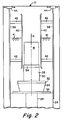
- Fig. 2 is a somewhat schematic representation of essential operating portions of the drying apparatus embodying the present invention.
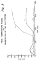
- Fig. 3 is a graph illustrating the range of temperature within a honeycomb structure during a drying cycle, relative to the orientation of the dielectric electrodes.
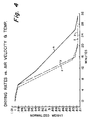
- Fig. 4 is a graph illustrating various drying rates which are obtainable with different air velocity and air temperature settings.
- the present invention incorporates the utilization of dielectric heating, a unique orientation of dielectric electrodes relative to the position of the honeycomb structure, the rotation of the honeycomb structure about its longitudinal axis, and the flowing of heated air through the longitudinally extending cells of the honeycomb structure to, in effect, produce a synergistic result.
- dielectric heating which is radio frequency (RF) heating, in which energy is released in a non-conducting medium through dielectric hysteresis.
- RF radio frequency
- dielectric drying over standard convection or oven drying is the fact that in RF drying, the energy passes through the entire honeycomb structure and is absorbed wherever there is water or other RF absorbing materials, and as a result the heating takes place throughout the honeycomb structure and the subsequent drying and shrinking are relatively uniform.
- the available RF fields are not uniform, and such fields are further modified by the presence of the wet honeycomb structure, resulting in a variable drying pattern.
- RF drying is preferable to convection drying, a non-uniformity still exists which can result in the dryest parts of a structure becoming overheated and damaged when attempting to dry the wettest parts of the honeycomb.
- hot air is passed longitudinally through the cells of the honeycomb structure.
- the hot air serves to remove evaporated moisture which otherwise must diffuse out of the honeycomb channels or cells.
- the partial pressure of water vapor in the cells is greatly reduced and the evaporation rate increases.
- the apparatus includes a drying oven 10, an RF power unit and control cabinet 12, and a control cabinet 14 for controlling the velocity and temperature of the air supplied to the honeycomb structure, and the rate of rotation of the turntable upon which the honeycomb structure is positioned.
- the drying oven 10 is provided with an access door 16 and a suitable heater 18 for heating the air to be supplied to the ware, and a fan 20 for controlling the velocity of the air supplied to the honeycomb structure.
- FIG. 2 the interior working structure of the drying oven 10 is schematically disclosed.
- a turntable 22 is rotatably mounted upon a lower support structure 24.
- An air inlet duct 26 communicates with the turntable 22 and is operably connected with the heater 18 and fan 20 positioned in the lower portion of the drying oven 10, which are controlled through control cabinet 14.
- the turntable 22 is mounted for rotation upon an upper surface of the lower support structure 24.
- the turntable is made of a material which is transparent to RF energy, such as most ceramics and plastics.
- a hollow carrier 28, having a cylindrical upper portion 30 and a lower disk portion 32, is positioned upon the upper open end of turntable 22, such that the disc portion 32 engages the open end of the turntable.
- the carrier 28 is made of a material, such as fiberglass/epoxy, and fired ceramic material (preferably, fired ceramic honeycomb), which is transparent to RF energy, and accordingly is not heated by such energy.
- a perforated support disc 34 which is transparent to RF energy, operatively fits within the upper open end of the carrier 28 and functions as an open free-flowing support for a green ceramic or wet honeycomb ware structure W positionable thereon.
- Heated air from the heater 18 is forced at a desired velocity by fan 20 through the air inlet duct 26 into the hollow turntable 22.
- the turntable may be provided with a plurality of air diverters in order to effect the distribution of the air flow upwardly through the hollow carrier 28, the open honeycomb support disk 34 and through the longitudinal cells of the ware W.
- the turntable 22, carrier 28 and disk support 34 are all aligned so that the longitudinal axis A of the honeycomb ware structure W is coincident with the axis of rotation of the turntable 22.
- the turntable 22 rotates the honeycomb ware W about its longitudinal axis A, which extends parallel with the longitudinally extending cells of the honeycomb structure.
- the flow of heated air, supplied to the honeycomb structure W also flows parallel with the longitudinal axis A and thus flows through the cells of the ware.
- a pair of support plates 38 are positioned within the drying oven 10 and support dielectric electrodes 40 by means of insulated standoffs 42.
- the electrodes 40 are preferably planar and extend parallel with the longitudinal axis A of the honeycomb ware W, but could be contoured to complement the curvature of the ware in a batch process, if desired.
- the support plates 38 may be secured to the lower support structure 24 and the shell or inner wall 11 of the drying oven 10, as shown, or they may be adjustably positioned on support rods so as to be able to vary the spacing between the electrodes 40. That is, when the drying oven 10 is to be utilized solely for a given product size, the support plates 38 may be permanently affixed with a given electrode spacing. However, when a plurality of ware sizes are to be utilized in a given oven, it is preferable to have the support plates adjustably mounted on support rods operatively attached to the oven structure.
- the support plates 38 would not be secured to supporting structure of the oven 10, but rather could be attached to motorized screw adjustment means 44, such as shown at the top of the support plates 38. If desired, such motorized screw adjustment means could be secured to suitable support rods secured to the frame of the oven 10.
- the dielectric electrodes 40 are of course operatively connected to the RF power unit 12 by suitable leads 41.
- the oven 10 would extend longitudinally into the page of the figure, and the upper surface 36 of the lower support structure 24 would be in the form of a conveyor or a series of trollies for moving a plurality of turntables 22 longitudinally there along into the page of Fig. 2, while incorporating suitable gearing for rotating each table and its associated carrier and ware, such that the ware is rotated about its longitudinal axis as it moves parallel with and between the electrodes 40, also extending into the page of the figure.
- the air duct 26 would extend along underneath the trollies or conveying mechanism 36.
- the electrodes 40 are positioned parallel to one another at a desired spacing relative to the wet honeycomb ware structure to be dried.
- the electrodes are evenly spaced from the axis A of rotation of the turntable 22.
- a green ceramic or wet honeycomb ware structure W to be dried is positioned upon the open or honeycomb support disk 34, such that its longitudinal axis A is virtually coincident with the axis of rotation of the turntable 22.
- the turntable 22 is then energized by control cabinet 14 to rotate the ware W about its longitudinal axis A on the support disk 34 evenly between the electrodes 40, which are oriented parallel with the longitudinal axis A of the ware W.
- the rotation of the turntable 22, controlled by control cabinet 14, may vary from about 1/4 rpm to about 10 rpm, with a preferred range being between about 1 and 6 rpm.
- An RF generator is positioned within and controlled by control cabinet 12 to supply RF energy via leads 41 to the electrodes 40 to produce an RF field therebetween.
- the amount of voltage applied to the electrodes 40 will of course vary depending upon the size of the RF generator being utilized, the size of the ware item being dried, and the moisture content within such ware. However, with a 10-KW RF generator, voltages of about 10 to 20 KV have been successfully applied.
- ware item W rotating about its longitudinal axis A between the RF energized electrodes 40, extending parallel to said longitudinal axis, it is preferred to delay the application of forced heated air through inlet duct 26 until evaporation of water from the cell walls is substantially uniform throughout the length of the ware.
- the length of the delay or the point at which this uniform evaporation is attained for a given ware is determined by experimentation. In general, the appropriate delay will depend on process variables such as the RF energy level, air flow rate, air temperature, the size and shape of the ware, ware composition etc.
- One indicator of the point at which forced heated air can be applied without stress cracking i.e., when uniform water evaporation is attained
- ware temperature For example, for the large ceramic bodies used for experimentation, we observed that uniform water evaporation was attained at ware temperatures of 80 to 90 °C. At these ware temperatures, forced air flow did not produce stress cracking in the ceramic ware.
- heated forced air is applied through inlet air duct 26 by means of heater 18 and fan 20, as controlled by control cabinet 14.
- the heated air flow from inlet duct 26 passes through the turntable 22, the hollow carrier 28, through the openings of the honeycomb disk support 34, and upwardly longitudinally through the longitudinally extending cells of the honeycomb structure W.
- the temperature and velocity of the air supplied to the honeycomb ware W to be dried, is controlled by the control cabinet 14 which operates the heater 18 and the fan 20.
- air temperatures between about 80°C and 150°C have been successfully utilized, it is preferred to utilize an air flow at a temperature of about 100°C + or - 20°.
- air velocities between about 2 meters per second and 5 meters per second have been successfully utilized.
- the velocity of the air supplied to the ware W may be varied during the drying process, if desired, such that a reduced initial velocity may be supplied and then a greater velocity may be provided to hasten the final drying.
- the green ceramic or wet honeycomb ware W is placed with its longitudinal channels or cells parallel to the electrodes 40, and rotated about its longitudinal axis A in the RF field, all parts of the ware are exposed to the same RF field, thus producing a uniform energy transfer by leveling the non-uniformities and variations of the RF field to produce a virtually stress-free drying of the ware.
- Fig. 3 shows the variation in temperature within a ware piece during an RF drying cycle, wherein the line a of the graph shows a temperature variation of about 140°C within a ware piece when the dielectric electrodes are positioned perpendicular to the longitudinal axis of the ware.
- the line b of the graph shows a temperature variation of only about 50°C within a ware piece when the dielectric electrodes are positioned parallel to the longitudinal axis of the ware.
- the line c shows a variation of less than 10° within a ware piece when the dielectric electrodes are positioned parallel to the longitudinal axis of the ware piece, the ware piece is rotated about its longitudinal axis between such parallel electrodes, and air is blown longitudinally through the piece, providing what might be considered a synergistic effect.
- a further advantage of orienting the dielectric electrodes parallel with the longitudinal axis of the honeycomb ware is the fact that the ends of the ware, through which the heated air is blown for drying, are not obstructed by the electrodes, and accordingly the removal of water from the honeycomb ware is not inhibited by the placement of the electrodes.
- the blowing of heated air parallel with the longitudinal axis and through the channels of the honeycomb ware functions to remove water vapors and reduce the vapor pressure in the channels, which further accelerates the rate of water evaporation from the honeycomb walls.
- the air can have different velocities, temperature and humidity contents, and by varying the same, the drying process can be shaped as desired.
- a green ceramic honeycomb extrusion approximately 13.5 inches in diameter and 17 inches in length, and weighing about 60 lbs., was positioned on the honeycomb support disk 34, with the longitudinal axis A thereof being virtually coincident with the axis of turntable 22 and parallel with the dielectric electrodes 40 which were spaced apart with an electrode gap of 15.5 inches.
- RF energy was applied to the electrodes 40 by means of control cabinet 14 at about 18 KV while the ware was rotated about its longitudinal axis at 6 rpm. After a period of 6 minutes, air at 100°C was introduced through inlet duct 26 at a velocity of about 2 meters per second for flow longitudinally through the longitudinal cells of the ware W.
- the present invention may be applied to wet honeycomb structures of virtually any size and transverse cross-sectional shape, it will be apparent that the drying uniformity obtained through the rotation of the structure about its longitudinal axis makes the invention especially useful for those honeycomb structures having circular, oval or regular polygonal transverse external cross-sections, and particularly those exhibiting relatively large cross-sectional diameters of at least about 8 inches.
Landscapes
- Engineering & Computer Science (AREA)
- Mechanical Engineering (AREA)
- Life Sciences & Earth Sciences (AREA)
- General Engineering & Computer Science (AREA)
- Microbiology (AREA)
- Ceramic Engineering (AREA)
- Biomedical Technology (AREA)
- Molecular Biology (AREA)
- Biotechnology (AREA)
- Health & Medical Sciences (AREA)
- Structural Engineering (AREA)
- Chemical & Material Sciences (AREA)
- Devices For Post-Treatments, Processing, Supply, Discharge, And Other Processes (AREA)
- Drying Of Solid Materials (AREA)
Applications Claiming Priority (2)
| Application Number | Priority Date | Filing Date | Title |
|---|---|---|---|
| US23933 | 1993-02-26 | ||
| US08/023,933 US5263263A (en) | 1993-02-26 | 1993-02-26 | Rotary dielectric drying of ceramic honeycomb ware |
Publications (2)
| Publication Number | Publication Date |
|---|---|
| EP0618416A1 true EP0618416A1 (fr) | 1994-10-05 |
| EP0618416B1 EP0618416B1 (fr) | 2000-11-22 |
Family
ID=21818001
Family Applications (1)
| Application Number | Title | Priority Date | Filing Date |
|---|---|---|---|
| EP93120196A Expired - Lifetime EP0618416B1 (fr) | 1993-02-26 | 1993-12-15 | Séchage rotatif diélectrique d'articles céramiques en nid d'abeilles |
Country Status (5)
| Country | Link |
|---|---|
| US (1) | US5263263A (fr) |
| EP (1) | EP0618416B1 (fr) |
| JP (1) | JPH06298563A (fr) |
| KR (1) | KR940020086A (fr) |
| DE (1) | DE69329694T2 (fr) |
Cited By (1)
| Publication number | Priority date | Publication date | Assignee | Title |
|---|---|---|---|---|
| US8729436B2 (en) | 2008-05-30 | 2014-05-20 | Corning Incorporated | Drying process and apparatus for ceramic greenware |
Families Citing this family (25)
| Publication number | Priority date | Publication date | Assignee | Title |
|---|---|---|---|---|
| US5388345A (en) * | 1993-11-04 | 1995-02-14 | Corning Incorporated | Dielectric drying of metal structures |
| US5406058A (en) * | 1993-11-30 | 1995-04-11 | Corning Incorporated | Apparatus for drying ceramic structures using dielectric energy |
| DE19715839B4 (de) * | 1997-04-16 | 2004-02-12 | Gebrüder Lödige Maschinenbau-Gesellschaft mit beschränkter Haftung | Verfahren und Vorrichtung zur Reinigung von öl- und wasserhaltigen Walzzunderschlämmen |
| US6192599B1 (en) * | 1998-09-23 | 2001-02-27 | Bgf Industries, Inc. | Drying process for woven fabric intended for use as a reinforcing laminate in printed circuit boards |
| JP4453117B2 (ja) * | 1998-09-29 | 2010-04-21 | 株式会社デンソー | 六角ハニカム構造体の製造方法 |
| US6539644B1 (en) * | 2001-09-15 | 2003-04-01 | Corning Incorporated | Drying of ceramic honeycomb substrates |
| JP4069613B2 (ja) * | 2001-11-09 | 2008-04-02 | 株式会社デンソー | セラミックハニカム構造体の製造方法及び乾燥装置 |
| US7422719B2 (en) * | 2002-10-29 | 2008-09-09 | Corning Incorporated | Process for removing oil-based components and forming ceramic bodies |
| JP4713342B2 (ja) * | 2003-09-02 | 2011-06-29 | 日本碍子株式会社 | ハニカム成形体の乾燥方法及び乾燥装置 |
| CN101646538B (zh) * | 2007-03-28 | 2013-10-16 | 日本碍子株式会社 | 蜂窝成形体的干燥方法以及干燥装置 |
| US20090309252A1 (en) * | 2008-06-17 | 2009-12-17 | Century, Inc. | Method of controlling evaporation of a fluid in an article |
| US9545735B2 (en) * | 2008-08-20 | 2017-01-17 | Corning Incorporated | Methods for drying ceramic greenware using an electrode concentrator |
| JP4866889B2 (ja) * | 2008-09-26 | 2012-02-01 | 日本碍子株式会社 | ハニカム成形体の乾燥方法 |
| US20100130352A1 (en) * | 2008-11-25 | 2010-05-27 | Dabich Ii Leonard Charles | Methods For Processing Shaped Bodies |
| US20100127421A1 (en) * | 2008-11-25 | 2010-05-27 | Dabich Ii Leonard Charles | Bi-directional flow for processing shaped bodies |
| US20100127418A1 (en) * | 2008-11-25 | 2010-05-27 | Ronald Alan Davidson | Methods For Continuous Firing Of Shaped Bodies And Roller Hearth Furnaces Therefor |
| US20100304041A1 (en) * | 2009-05-29 | 2010-12-02 | Tonia Havewala Fletcher | Method For Coating Honeycomb Bodies |
| JP6189775B2 (ja) * | 2013-03-29 | 2017-08-30 | 日本碍子株式会社 | 分離膜の製造方法 |
| US10173933B2 (en) | 2013-05-06 | 2019-01-08 | Corning Incorporated | Rapid drying of ceramic greenwares |
| US11168033B2 (en) | 2017-03-24 | 2021-11-09 | Ngk Insulators, Ltd. | Method for drying columnar honeycomb formed body and method for producing columnar honeycomb structure |
| JP6559727B2 (ja) * | 2017-03-28 | 2019-08-14 | 日本碍子株式会社 | ハニカム構造体の製造方法 |
| US20180361619A1 (en) * | 2017-06-16 | 2018-12-20 | Guangzhen Zhou | Clay Body Moisture Control and Drying Apparatus |
| JP7422853B2 (ja) | 2020-02-20 | 2024-01-26 | 日本碍子株式会社 | セラミックス成形体の誘電乾燥方法及び誘電乾燥装置、並びにセラミックス構造体の製造方法 |
| JP7296926B2 (ja) | 2020-09-10 | 2023-06-23 | 日本碍子株式会社 | セラミックス成形体の誘電乾燥方法及びセラミックス構造体の製造方法 |
| JP6989723B1 (ja) | 2021-06-09 | 2022-01-05 | 日本碍子株式会社 | セラミックス成形体の誘電乾燥方法及び誘電乾燥装置、並びにセラミックス構造体の製造方法 |
Citations (7)
| Publication number | Priority date | Publication date | Assignee | Title |
|---|---|---|---|---|
| GB957320A (en) * | 1961-09-15 | 1964-05-06 | Radyne Ltd | Improvements in or relating to dielectric heating apparatus |
| FR2299443A1 (fr) * | 1974-10-11 | 1976-08-27 | Mhm Electronic | Dispositif de sechage et de traitement thermique de fils textiles par pertes dielectriques |
| EP0023940A1 (fr) * | 1979-08-08 | 1981-02-18 | Dawson International Public Limited Company | Procédé et appareil pour le séchage par haute fréquence de matière textile |
| EP0077969A1 (fr) * | 1981-10-23 | 1983-05-04 | Siemens Aktiengesellschaft | Installation de séchage de bobines de teintures |
| US4439929A (en) * | 1981-02-23 | 1984-04-03 | Ngk Insulators, Ltd. | Apparatus for drying a ceramic green honeycomb body |
| WO1988000678A1 (fr) * | 1986-07-11 | 1988-01-28 | Max Wagner | Procede et dispositif de sechage de corps ceramiques creux |
| EP0273707A2 (fr) * | 1986-12-27 | 1988-07-06 | Ngk Insulators, Ltd. | Procédé de séchage diélectrique pour des structures en nid d'abeilles |
Family Cites Families (11)
| Publication number | Priority date | Publication date | Assignee | Title |
|---|---|---|---|---|
| DE141970C (fr) * | ||||
| US2737569A (en) * | 1951-08-02 | 1956-03-06 | Skenandoa Rayon Corp | Electrode structure for high frequency drier |
| DE1584771A1 (de) * | 1964-10-01 | 1971-04-15 | Tesla Np | Strangpresse fuer im plastischen Zustand gezogenes,feuchtes,keramisches Material |
| US3953703A (en) * | 1974-10-03 | 1976-04-27 | Materials Research Corporation | Method for drying ceramic tape |
| JPS6034510B2 (ja) * | 1976-06-10 | 1985-08-09 | 日本碍子株式会社 | セラミツクハニカム構造体の押出製造法 |
| US4492571A (en) * | 1981-07-31 | 1985-01-08 | Toyo Seikan Kaisha, Ltd. | Baking and drying furnace for containers such as cans |
| US4629849A (en) * | 1984-06-28 | 1986-12-16 | Ngk Insulators Ltd. | Microwave heating device having a rotary reflector means in a heating chamber |
| JPS61151289U (fr) * | 1985-03-12 | 1986-09-18 | ||
| JPS61275169A (ja) * | 1985-05-07 | 1986-12-05 | 日本碍子株式会社 | セラミツクス成形体の乾燥方法及びその治具 |
| JPS63102912A (ja) * | 1986-10-18 | 1988-05-07 | 日本碍子株式会社 | セラミツク筒体の押出乾燥法 |
| DE3635542A1 (de) * | 1986-10-18 | 1988-04-28 | Philips Patentverwaltung | Verfahren und vorrichtung zum trocknen keramischer gruenkoerper |
-
1993
- 1993-02-26 US US08/023,933 patent/US5263263A/en not_active Expired - Lifetime
- 1993-12-15 EP EP93120196A patent/EP0618416B1/fr not_active Expired - Lifetime
- 1993-12-15 DE DE69329694T patent/DE69329694T2/de not_active Expired - Fee Related
-
1994
- 1994-02-25 KR KR1019940003526A patent/KR940020086A/ko not_active Abandoned
- 1994-02-28 JP JP6029473A patent/JPH06298563A/ja not_active Withdrawn
Patent Citations (7)
| Publication number | Priority date | Publication date | Assignee | Title |
|---|---|---|---|---|
| GB957320A (en) * | 1961-09-15 | 1964-05-06 | Radyne Ltd | Improvements in or relating to dielectric heating apparatus |
| FR2299443A1 (fr) * | 1974-10-11 | 1976-08-27 | Mhm Electronic | Dispositif de sechage et de traitement thermique de fils textiles par pertes dielectriques |
| EP0023940A1 (fr) * | 1979-08-08 | 1981-02-18 | Dawson International Public Limited Company | Procédé et appareil pour le séchage par haute fréquence de matière textile |
| US4439929A (en) * | 1981-02-23 | 1984-04-03 | Ngk Insulators, Ltd. | Apparatus for drying a ceramic green honeycomb body |
| EP0077969A1 (fr) * | 1981-10-23 | 1983-05-04 | Siemens Aktiengesellschaft | Installation de séchage de bobines de teintures |
| WO1988000678A1 (fr) * | 1986-07-11 | 1988-01-28 | Max Wagner | Procede et dispositif de sechage de corps ceramiques creux |
| EP0273707A2 (fr) * | 1986-12-27 | 1988-07-06 | Ngk Insulators, Ltd. | Procédé de séchage diélectrique pour des structures en nid d'abeilles |
Cited By (1)
| Publication number | Priority date | Publication date | Assignee | Title |
|---|---|---|---|---|
| US8729436B2 (en) | 2008-05-30 | 2014-05-20 | Corning Incorporated | Drying process and apparatus for ceramic greenware |
Also Published As
| Publication number | Publication date |
|---|---|
| JPH06298563A (ja) | 1994-10-25 |
| US5263263A (en) | 1993-11-23 |
| DE69329694T2 (de) | 2001-03-15 |
| KR940020086A (ko) | 1994-09-15 |
| EP0618416B1 (fr) | 2000-11-22 |
| DE69329694D1 (de) | 2000-12-28 |
Similar Documents
| Publication | Publication Date | Title |
|---|---|---|
| US5263263A (en) | Rotary dielectric drying of ceramic honeycomb ware | |
| US4439929A (en) | Apparatus for drying a ceramic green honeycomb body | |
| JP4713342B2 (ja) | ハニカム成形体の乾燥方法及び乾燥装置 | |
| CA1287118C (fr) | Methode de sechage par voie dielectrique pour structure alveolees | |
| CN101538147A (zh) | 成型陶瓷制品的干燥方法 | |
| CN112665347B (zh) | 一种便于对陶瓷固定的陶瓷制作用烘干装置 | |
| CN209983505U (zh) | 一种烟草烘烤装置 | |
| CN100577383C (zh) | 蜂窝状成型体的干燥方法及干燥装置 | |
| US20030051368A1 (en) | Drying of ceramic honeycomb substrates | |
| JP2001130973A5 (fr) | ||
| JP2001130973A (ja) | セラミック成形体の乾燥方法 | |
| CN207815891U (zh) | 一种微波组合干燥矿物的装置 | |
| HU194141B (en) | Process and apparatus for drying ceramic semi-finished products | |
| JP4386518B2 (ja) | セラミック成形体の乾燥方法及びセラミック成形体の乾燥用治具 | |
| CN208091082U (zh) | 一种热风循环烘箱 | |
| NO902312D0 (no) | Fremgangsmaate og anordning for fremstilling av store formlegemer med lav tetthet. | |
| JP2831046B2 (ja) | 成形体の乾燥方法 | |
| JPH07294122A (ja) | セラミックグリーンシート乾燥装置及びセラミックグリーンシート乾燥方法 | |
| CS215851B1 (en) | Method of heat treating ceramic semifinished products | |
| US3393256A (en) | Process for maintaining straightness in extruded ceramic sections | |
| CN113405323A (zh) | 一种用于蜂窝scr脱硝催化剂的微波干燥方法及装置 | |
| JP2610767B2 (ja) | セラミック成形体の乾燥方法およびそれに用いる装置 | |
| CN222617489U (zh) | 一种陶瓷颜料节能干燥设备 | |
| CN109556350A (zh) | 陶瓷坯体的微波干燥方法及装置 | |
| CN222598281U (zh) | 一种建筑模板自动干燥机 |
Legal Events
| Date | Code | Title | Description |
|---|---|---|---|
| PUAI | Public reference made under article 153(3) epc to a published international application that has entered the european phase |
Free format text: ORIGINAL CODE: 0009012 |
|
| AK | Designated contracting states |
Kind code of ref document: A1 Designated state(s): BE DE |
|
| 17P | Request for examination filed |
Effective date: 19950327 |
|
| 17Q | First examination report despatched |
Effective date: 19960402 |
|
| GRAG | Despatch of communication of intention to grant |
Free format text: ORIGINAL CODE: EPIDOS AGRA |
|
| 17Q | First examination report despatched |
Effective date: 19970402 |
|
| GRAG | Despatch of communication of intention to grant |
Free format text: ORIGINAL CODE: EPIDOS AGRA |
|
| GRAH | Despatch of communication of intention to grant a patent |
Free format text: ORIGINAL CODE: EPIDOS IGRA |
|
| GRAH | Despatch of communication of intention to grant a patent |
Free format text: ORIGINAL CODE: EPIDOS IGRA |
|
| GRAA | (expected) grant |
Free format text: ORIGINAL CODE: 0009210 |
|
| AK | Designated contracting states |
Kind code of ref document: B1 Designated state(s): BE DE |
|
| REF | Corresponds to: |
Ref document number: 69329694 Country of ref document: DE Date of ref document: 20001228 |
|
| EN | Fr: translation not filed | ||
| PLBE | No opposition filed within time limit |
Free format text: ORIGINAL CODE: 0009261 |
|
| 26N | No opposition filed | ||
| PGFP | Annual fee paid to national office [announced via postgrant information from national office to epo] |
Ref country code: DE Payment date: 20021230 Year of fee payment: 10 |
|
| PG25 | Lapsed in a contracting state [announced via postgrant information from national office to epo] |
Ref country code: DE Free format text: LAPSE BECAUSE OF NON-PAYMENT OF DUE FEES Effective date: 20040701 |
|
| PGFP | Annual fee paid to national office [announced via postgrant information from national office to epo] |
Ref country code: BE Payment date: 20070206 Year of fee payment: 14 |
|
| BERE | Be: lapsed |
Owner name: CORNING INC. Effective date: 20071231 |
|
| PG25 | Lapsed in a contracting state [announced via postgrant information from national office to epo] |
Ref country code: BE Free format text: LAPSE BECAUSE OF NON-PAYMENT OF DUE FEES Effective date: 20071231 |