EP0618465B1 - Guide d'ondes rempli de fluide - Google Patents
Guide d'ondes rempli de fluide Download PDFInfo
- Publication number
- EP0618465B1 EP0618465B1 EP19940302329 EP94302329A EP0618465B1 EP 0618465 B1 EP0618465 B1 EP 0618465B1 EP 19940302329 EP19940302329 EP 19940302329 EP 94302329 A EP94302329 A EP 94302329A EP 0618465 B1 EP0618465 B1 EP 0618465B1
- Authority
- EP
- European Patent Office
- Prior art keywords
- cladding
- optical waveguide
- hose
- core
- rubber
- Prior art date
- Legal status (The legal status is an assumption and is not a legal conclusion. Google has not performed a legal analysis and makes no representation as to the accuracy of the status listed.)
- Expired - Lifetime
Links
- 239000012530 fluid Substances 0.000 title claims description 27
- 230000003287 optical effect Effects 0.000 title claims description 26
- 238000005253 cladding Methods 0.000 claims description 78
- 239000000463 material Substances 0.000 claims description 32
- 238000007789 sealing Methods 0.000 claims description 7
- 239000011247 coating layer Substances 0.000 claims description 6
- 238000000149 argon plasma sintering Methods 0.000 claims description 4
- 239000013013 elastic material Substances 0.000 claims description 4
- 229920001973 fluoroelastomer Polymers 0.000 claims description 4
- 239000012260 resinous material Substances 0.000 claims description 4
- 229920002379 silicone rubber Polymers 0.000 claims description 4
- 239000004945 silicone rubber Substances 0.000 claims description 3
- 229920005560 fluorosilicone rubber Polymers 0.000 claims description 2
- 239000011162 core material Substances 0.000 description 33
- 239000007788 liquid Substances 0.000 description 17
- 239000007789 gas Substances 0.000 description 15
- 229920001971 elastomer Polymers 0.000 description 14
- 239000005060 rubber Substances 0.000 description 12
- 239000013307 optical fiber Substances 0.000 description 11
- 239000011521 glass Substances 0.000 description 10
- 230000035515 penetration Effects 0.000 description 9
- -1 dimethylsiloxane Chemical class 0.000 description 8
- VYPSYNLAJGMNEJ-UHFFFAOYSA-N Silicium dioxide Chemical compound O=[Si]=O VYPSYNLAJGMNEJ-UHFFFAOYSA-N 0.000 description 7
- 229920003023 plastic Polymers 0.000 description 6
- 239000000835 fiber Substances 0.000 description 5
- 229910052751 metal Inorganic materials 0.000 description 5
- 239000002184 metal Substances 0.000 description 5
- 239000004033 plastic Substances 0.000 description 5
- 238000002834 transmittance Methods 0.000 description 5
- 238000000576 coating method Methods 0.000 description 4
- 229920001577 copolymer Polymers 0.000 description 4
- 229920000642 polymer Polymers 0.000 description 4
- 239000010453 quartz Substances 0.000 description 4
- 229920005989 resin Polymers 0.000 description 4
- 239000011347 resin Substances 0.000 description 4
- LYCAIKOWRPUZTN-UHFFFAOYSA-N Ethylene glycol Chemical compound OCCO LYCAIKOWRPUZTN-UHFFFAOYSA-N 0.000 description 3
- 230000005540 biological transmission Effects 0.000 description 3
- 239000011248 coating agent Substances 0.000 description 3
- 239000010410 layer Substances 0.000 description 3
- 239000003921 oil Substances 0.000 description 3
- 238000004804 winding Methods 0.000 description 3
- YEVQZPWSVWZAOB-UHFFFAOYSA-N 2-(bromomethyl)-1-iodo-4-(trifluoromethyl)benzene Chemical compound FC(F)(F)C1=CC=C(I)C(CBr)=C1 YEVQZPWSVWZAOB-UHFFFAOYSA-N 0.000 description 2
- PEDCQBHIVMGVHV-UHFFFAOYSA-N Glycerine Chemical compound OCC(O)CO PEDCQBHIVMGVHV-UHFFFAOYSA-N 0.000 description 2
- 229920002367 Polyisobutene Polymers 0.000 description 2
- CCDWGDHTPAJHOA-UHFFFAOYSA-N benzylsilicon Chemical compound [Si]CC1=CC=CC=C1 CCDWGDHTPAJHOA-UHFFFAOYSA-N 0.000 description 2
- 230000000052 comparative effect Effects 0.000 description 2
- 230000008602 contraction Effects 0.000 description 2
- 239000000806 elastomer Substances 0.000 description 2
- 229910010272 inorganic material Inorganic materials 0.000 description 2
- 239000011147 inorganic material Substances 0.000 description 2
- 150000002739 metals Chemical class 0.000 description 2
- 229920001921 poly-methyl-phenyl-siloxane Polymers 0.000 description 2
- 229920000058 polyacrylate Polymers 0.000 description 2
- 229920000728 polyester Polymers 0.000 description 2
- 239000007787 solid Substances 0.000 description 2
- 239000000243 solution Substances 0.000 description 2
- 229920003048 styrene butadiene rubber Polymers 0.000 description 2
- 229920001897 terpolymer Polymers 0.000 description 2
- 238000011282 treatment Methods 0.000 description 2
- YMRMDGSNYHCUCL-UHFFFAOYSA-N 1,2-dichloro-1,1,2-trifluoroethane Chemical compound FC(Cl)C(F)(F)Cl YMRMDGSNYHCUCL-UHFFFAOYSA-N 0.000 description 1
- NNWNNQTUZYVQRK-UHFFFAOYSA-N 5-bromo-1h-pyrrolo[2,3-c]pyridine-2-carboxylic acid Chemical compound BrC1=NC=C2NC(C(=O)O)=CC2=C1 NNWNNQTUZYVQRK-UHFFFAOYSA-N 0.000 description 1
- RZVAJINKPMORJF-UHFFFAOYSA-N Acetaminophen Chemical compound CC(=O)NC1=CC=C(O)C=C1 RZVAJINKPMORJF-UHFFFAOYSA-N 0.000 description 1
- OMFMOEOGTAYVMW-UHFFFAOYSA-N CC=C.C=C.C=C(F)F.F.F.F.F.F.F.F.F.F.F Chemical compound CC=C.C=C.C=C(F)F.F.F.F.F.F.F.F.F.F.F OMFMOEOGTAYVMW-UHFFFAOYSA-N 0.000 description 1
- AUPYOEILHQZNDV-UHFFFAOYSA-N CC=C.C=C.F.F.F.F Chemical group CC=C.C=C.F.F.F.F AUPYOEILHQZNDV-UHFFFAOYSA-N 0.000 description 1
- 229920002574 CR-39 Polymers 0.000 description 1
- 229910020323 ClF3 Inorganic materials 0.000 description 1
- 239000004641 Diallyl-phthalate Substances 0.000 description 1
- 229920002943 EPDM rubber Polymers 0.000 description 1
- 229920000181 Ethylene propylene rubber Polymers 0.000 description 1
- 244000043261 Hevea brasiliensis Species 0.000 description 1
- 229910019142 PO4 Inorganic materials 0.000 description 1
- 239000002033 PVDF binder Substances 0.000 description 1
- 239000004952 Polyamide Substances 0.000 description 1
- 239000004698 Polyethylene Substances 0.000 description 1
- 239000004642 Polyimide Substances 0.000 description 1
- 239000004743 Polypropylene Substances 0.000 description 1
- 239000004793 Polystyrene Substances 0.000 description 1
- 229920007962 Styrene Methyl Methacrylate Polymers 0.000 description 1
- 229920000800 acrylic rubber Polymers 0.000 description 1
- 229920000122 acrylonitrile butadiene styrene Polymers 0.000 description 1
- 229920001893 acrylonitrile styrene Polymers 0.000 description 1
- 229920001898 acrylonitrile–EPDM–styrene Polymers 0.000 description 1
- 229910052782 aluminium Inorganic materials 0.000 description 1
- XAGFODPZIPBFFR-UHFFFAOYSA-N aluminium Chemical compound [Al] XAGFODPZIPBFFR-UHFFFAOYSA-N 0.000 description 1
- 239000007864 aqueous solution Substances 0.000 description 1
- 230000004888 barrier function Effects 0.000 description 1
- 238000005452 bending Methods 0.000 description 1
- 230000015572 biosynthetic process Effects 0.000 description 1
- QUDWYFHPNIMBFC-UHFFFAOYSA-N bis(prop-2-enyl) benzene-1,2-dicarboxylate Chemical compound C=CCOC(=O)C1=CC=CC=C1C(=O)OCC=C QUDWYFHPNIMBFC-UHFFFAOYSA-N 0.000 description 1
- 229920005549 butyl rubber Polymers 0.000 description 1
- 150000004649 carbonic acid derivatives Chemical class 0.000 description 1
- 229910010293 ceramic material Inorganic materials 0.000 description 1
- 238000006243 chemical reaction Methods 0.000 description 1
- 229920006026 co-polymeric resin Polymers 0.000 description 1
- 238000010073 coating (rubber) Methods 0.000 description 1
- 239000008199 coating composition Substances 0.000 description 1
- 238000004891 communication Methods 0.000 description 1
- 239000002131 composite material Substances 0.000 description 1
- 238000010276 construction Methods 0.000 description 1
- 230000007423 decrease Effects 0.000 description 1
- 230000003247 decreasing effect Effects 0.000 description 1
- 239000004205 dimethyl polysiloxane Substances 0.000 description 1
- 230000005489 elastic deformation Effects 0.000 description 1
- 229920005558 epichlorohydrin rubber Polymers 0.000 description 1
- 239000003822 epoxy resin Substances 0.000 description 1
- 230000008020 evaporation Effects 0.000 description 1
- 238000001704 evaporation Methods 0.000 description 1
- 238000001125 extrusion Methods 0.000 description 1
- 239000003365 glass fiber Substances 0.000 description 1
- 230000009477 glass transition Effects 0.000 description 1
- 235000011187 glycerol Nutrition 0.000 description 1
- 238000009499 grossing Methods 0.000 description 1
- 229920005555 halobutyl Polymers 0.000 description 1
- 150000008282 halocarbons Chemical class 0.000 description 1
- LNEPOXFFQSENCJ-UHFFFAOYSA-N haloperidol Chemical compound C1CC(O)(C=2C=CC(Cl)=CC=2)CCN1CCCC(=O)C1=CC=C(F)C=C1 LNEPOXFFQSENCJ-UHFFFAOYSA-N 0.000 description 1
- 229930195733 hydrocarbon Natural products 0.000 description 1
- 150000002430 hydrocarbons Chemical class 0.000 description 1
- 238000005286 illumination Methods 0.000 description 1
- 230000005764 inhibitory process Effects 0.000 description 1
- 239000004816 latex Substances 0.000 description 1
- 229920000126 latex Polymers 0.000 description 1
- 229940057995 liquid paraffin Drugs 0.000 description 1
- 239000007769 metal material Substances 0.000 description 1
- 125000005395 methacrylic acid group Chemical group 0.000 description 1
- ADFPJHOAARPYLP-UHFFFAOYSA-N methyl 2-methylprop-2-enoate;styrene Chemical compound COC(=O)C(C)=C.C=CC1=CC=CC=C1 ADFPJHOAARPYLP-UHFFFAOYSA-N 0.000 description 1
- 229920003052 natural elastomer Polymers 0.000 description 1
- 229920001194 natural rubber Polymers 0.000 description 1
- 238000012856 packing Methods 0.000 description 1
- 230000000149 penetrating effect Effects 0.000 description 1
- 235000021317 phosphate Nutrition 0.000 description 1
- 150000003013 phosphoric acid derivatives Chemical class 0.000 description 1
- 238000007747 plating Methods 0.000 description 1
- 229920001084 poly(chloroprene) Polymers 0.000 description 1
- 229920000435 poly(dimethylsiloxane) Polymers 0.000 description 1
- 229920001200 poly(ethylene-vinyl acetate) Polymers 0.000 description 1
- 229920003229 poly(methyl methacrylate) Polymers 0.000 description 1
- 229920002492 poly(sulfone) Polymers 0.000 description 1
- 229920002647 polyamide Polymers 0.000 description 1
- 229920002857 polybutadiene Polymers 0.000 description 1
- 239000004417 polycarbonate Substances 0.000 description 1
- 229920000515 polycarbonate Polymers 0.000 description 1
- 229920000647 polyepoxide Polymers 0.000 description 1
- 229920000570 polyether Polymers 0.000 description 1
- 229920006393 polyether sulfone Polymers 0.000 description 1
- 229920001601 polyetherimide Polymers 0.000 description 1
- 229920000573 polyethylene Polymers 0.000 description 1
- 229920000139 polyethylene terephthalate Polymers 0.000 description 1
- 239000005020 polyethylene terephthalate Substances 0.000 description 1
- 229920001721 polyimide Polymers 0.000 description 1
- 229920001195 polyisoprene Polymers 0.000 description 1
- 238000006116 polymerization reaction Methods 0.000 description 1
- 239000004926 polymethyl methacrylate Substances 0.000 description 1
- 229920000306 polymethylpentene Polymers 0.000 description 1
- 239000011116 polymethylpentene Substances 0.000 description 1
- 229920000098 polyolefin Polymers 0.000 description 1
- 229920001155 polypropylene Polymers 0.000 description 1
- 229920002223 polystyrene Polymers 0.000 description 1
- 229920002635 polyurethane Polymers 0.000 description 1
- 239000004814 polyurethane Substances 0.000 description 1
- 239000004800 polyvinyl chloride Substances 0.000 description 1
- 229920000915 polyvinyl chloride Polymers 0.000 description 1
- 229920002620 polyvinyl fluoride Polymers 0.000 description 1
- 229920002981 polyvinylidene fluoride Polymers 0.000 description 1
- 239000002243 precursor Substances 0.000 description 1
- SCUZVMOVTVSBLE-UHFFFAOYSA-N prop-2-enenitrile;styrene Chemical compound C=CC#N.C=CC1=CC=CC=C1 SCUZVMOVTVSBLE-UHFFFAOYSA-N 0.000 description 1
- 239000005297 pyrex Substances 0.000 description 1
- 150000003839 salts Chemical class 0.000 description 1
- 239000010980 sapphire Substances 0.000 description 1
- 229910052594 sapphire Inorganic materials 0.000 description 1
- 229920002545 silicone oil Polymers 0.000 description 1
- 229920002050 silicone resin Polymers 0.000 description 1
- 239000011343 solid material Substances 0.000 description 1
- 239000002904 solvent Substances 0.000 description 1
- 238000004544 sputter deposition Methods 0.000 description 1
- 229910001220 stainless steel Inorganic materials 0.000 description 1
- 239000010935 stainless steel Substances 0.000 description 1
- 150000005846 sugar alcohols Polymers 0.000 description 1
- 150000003457 sulfones Chemical class 0.000 description 1
- 238000004381 surface treatment Methods 0.000 description 1
- 230000008961 swelling Effects 0.000 description 1
- 230000002195 synergetic effect Effects 0.000 description 1
- 238000005382 thermal cycling Methods 0.000 description 1
- 229920002725 thermoplastic elastomer Polymers 0.000 description 1
- 239000012780 transparent material Substances 0.000 description 1
- JOHWNGGYGAVMGU-UHFFFAOYSA-N trifluorochlorine Chemical compound FCl(F)F JOHWNGGYGAVMGU-UHFFFAOYSA-N 0.000 description 1
- HQUQLFOMPYWACS-UHFFFAOYSA-N tris(2-chloroethyl) phosphate Chemical compound ClCCOP(=O)(OCCCl)OCCCl HQUQLFOMPYWACS-UHFFFAOYSA-N 0.000 description 1
Images

Classifications
-
- G—PHYSICS
- G02—OPTICS
- G02B—OPTICAL ELEMENTS, SYSTEMS OR APPARATUS
- G02B6/00—Light guides; Structural details of arrangements comprising light guides and other optical elements, e.g. couplings
- G02B6/02—Optical fibres with cladding with or without a coating
- G02B6/032—Optical fibres with cladding with or without a coating with non solid core or cladding
-
- G—PHYSICS
- G02—OPTICS
- G02B—OPTICAL ELEMENTS, SYSTEMS OR APPARATUS
- G02B6/00—Light guides; Structural details of arrangements comprising light guides and other optical elements, e.g. couplings
- G02B6/0001—Light guides; Structural details of arrangements comprising light guides and other optical elements, e.g. couplings specially adapted for lighting devices or systems
Definitions
- This invention generally relates to optical waveguides having a fluid core, and more particularly, to an optical waveguide hose having a fluid core which is designed to prevent penetration of gas into the core, to help maintain its function over a wide temperature range and a long period of time and with good flexibility.
- Well-known fiber optics include optical fibers of inorganic glass systems such as quartz glass and multi - component glass and optical fibers of plastic systems such as polymethyl methacrylate and polystyrene. These are all solid optical fibers wherein both the core and the cladding are solid materials. Although these optical fibers have satisfactory characteristics, they are limited in flexibility because they are formed from glass or hard plastics. Also, when it is desired to increase the diameter for transmitting a large quantity of light, a plurality of optical fibers each having a diameter of about 10 to 1,000 ⁇ m must be bundled. The optical fiber bundle has a space left among fibers even when fibers are packed at a possible maximum packing density and thus has a reduced effective inlet surface area for receiving light. The bundle is then low in efficiency and rather expensive.
- the liquid system optical fiber includes a cladding in the form of a flexible hollow tube and a liquid core therein having a higher index of refraction than the cladding. Opposite end openings of the cladding are closed with window members. This allows the fiber to have a large diameter and a large effective light-receiving area and the fiber is thus highly efficient and cost effective.
- the liquid system optical fiber had excellent features as mentioned above, it has the problem that since its stiffness is provided by a cladding in the form of a flexible hollow tubular member, gases can penetrate into the core liquid to lower its transparency due to a change in the service environment temperature during a long period of use. This is because the core is liquid and thus has a higher coefficient of expansion than the hollow tubular cladding generally formed of resinous material. At low temperatures, the volume of the core liquid is smaller than the interior volume of the cladding so that the hollow interior of the cladding is under negative pressure, encouraging gases to penetrate thereto through the cladding wall, creating bubbles in the core liquid. Bubble formation is facilitated particularly when the temperature is once elevated and then decreased.
- GB-A-1,450,608 proposed a liquid system optical fiber aiming to solve the gas penetration problem.
- This optical fiber is provided with a core liquid reservoir connected to the hollow tubular cladding.
- the reservoir makes up the core liquid when the core liquid decreases its volume at low temperatures, preventing the hollow interior of the cladding from becoming negative in pressure and thus preventing gas penetration into the core liquid.
- This optical fiber required to form an aperture in the cladding for liquid communication before the reservoir could be connected to the hollow tubular cladding.
- This aperture caused light scattering and detracted from transparency.
- the attachment of the reservoir added to the weight and cost.
- the general aim of the invention as defined in claim 1 is to provide new constructions of fluid-filled optical waveguide, with low light scattering.
- Other preferred aims include the inhibition of gas penetration to the waveguide interior, good transparency, light weight, low cost and long life.
- One general proposal herein is the use of an elastic material for the cladding, whereby the cladding is elastically deformable to accommodate thermal expansion and contraction of the core fluid.
- Suitable examples of elastic cladding materials are disclosed herein.
- the cladding material may be sufficiently easily and elastically deformable to follow the thermal volume changes of the fluid such that pressure drops causing gas penetration of the cladding do not occur as temperature falls.
- Elastomeric, or rubbery elastic, materials are preferred.
- the core material increases its volume and the cladding can follow expansion by elastic deformation.
- the cladding follows contraction of the core. In this way the internal pressure is maintained. It never happens that the hollow interior of the cladding becomes negative in pressure and gases penetrate through the cladding wall to develop bubbles in the core fluid. Then an optical waveguide hose which remains transparent over a wide range of temperature and flexible even at a large diameter can be manufactured at low cost.
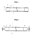
- FIG. 1 is a schematic axial cross section of an optical waveguide hose according to one embodiment of the invention.
- FIG. 2 is a schematic axial cross section of an optical waveguide hose according to another embodiment of the invention.
- FIG. 3 is a schematic axial cross section of an optical waveguide hose according to a further embodiment of the invention.
- An optical waveguide hose includes a hollow tubular cladding made of a material which exhibits elasticity at the working temperature of the hose.
- the cladding is filled with a core of a fluid having a higher index of refraction than the cladding.
- a sealing plug is mated with each end opening of the cladding.
- FIG. 1 there is illustrated a basic structure of an optical waveguide hose according to the present invention.
- the hose is shown in FIG. 1 as comprising a hollow tubular cladding 1 having opposite end openings, a fluid core 2 filled in the cladding 1, and a sealing plug 3 mated with each end opening of the cladding 1 for closing the openings for maintaining the interior pressure of the cladding hollow interior.
- a clamp 4 is fastened around each cladding end for preventing release of the sealing plug 3 and leakage of the core fluid.
- the hollow tubular cladding 1 is made of a material having rubber elasticity, over its entirety at the working temperature (usually - 50 to 150°C, especially - 30 to 120°C) of the hose.
- the cladding material be shapable into a tubular form, have a low index of refraction and be resistant against attack by the core fluid.
- the cladding material have sufficient gas barrier properties to prevent gas permeation.
- a choice of a cladding material having no substantial difference in coefficient of thermal expansion from the core fluid provides a synergistic effect coupled with its rubber elasticity. In this regard, it is preferred to use a cladding material having a coefficient of thermal expansion which is 0.5 to 3 times that of the core fluid.
- the cladding material has a lower glass transition temperature (Tg) than the service temperature and has been physically and chemically crosslinked for preventing creep, especially having low creep at the maximum service temperature.
- Tg glass transition temperature
- Illustrative examples of cladding materials obtainable to meet the above-mentioned requirements include flexible polyvinyl chloride, polyethylene-vinyl acetate copolymers, polyurethane, natural rubber, polyisoprene rubber, polybutadiene rubber, styrene-butadiene copolymers, butyl rubber, halogenated butyl rubber, chloroprene rubber, acrylic rubber, epichlorohydrin rubber, ethylene - propylene rubber, EPDM, acrylonitrile-butadiene copolymers, fluororubber, and silicone rubber.
- silicone elastomers such as dimethylsiloxane polymers, methylphenylsiloxane polymers, and fluorosilicone polymers, polyvinylidene fluoride, polyvinyl fluoride, vinylidene fluoride - trifluoroethylene chloride copolymers, vinylidene fluoride - propylene hexafluoride copolymers, vinylidene fluoride-propylene hexafluoride - ethylene tetrafluoride terpolymers, ethylene tetrafluoride - propylene rubber, and fluorinated thermoplastic elastomers. These are available with rubber elasticity.
- These cladding materials may be used alone or in admixture of two or more and formed as a single tube or multiple tubes.
- the interior surface of the cladding in contact with the core fluid is smoothed for the purpose of preventing light scattering, and also preventing swelling of the core fluid, and gas entry.
- suitable smoothing treatments may include double extrusion, treatment of the interior surface with reactive gas such as ClF 3 , and surface treatment by plasma initiated polymerization, in the present invention a coating method is advantageously used since it is relatively easy to form a coating layer on the interior surface of the cladding tube.
- the coating materials suitable to this end include precursors of the above-mentioned rubber elasticity materials, liquid rubber, latex, and rubber coating compositions.
- fluororubber, silicone rubber, and fluorosilicone rubber in solution form and liquid rubber may be used.
- the coating layer is preferably about 1 to 1000 ⁇ m thick.
- a resinous material is applicable to the interior surface of a rubber elastic tube to form a thin layer thereon with the results being comparable to those of a cladding tube made solely of a rubber elastic material.
- the resin thin layer is preferably about 0.1 to 100 ⁇ m thick, especially about 1 to 10 ⁇ m thick.
- the cladding on the outer surface may be covered with a coating material.
- the cladding tube may be coated with any of plastics and elastomers.
- any of metal materials such as stainless steel and aluminum, plastics, and elastomers is shaped into an elongated hollow member in the form of a pipe, bellows or spirally wound wire, and the optical waveguide hose is inserted into the hollow member. It is also possible to form a thin layer of inorganic material on the outer surface of the cladding by plating, evaporation and sputtering.
- These coating materials may be used alone or in combination with another material to form a composite cover.
- the core fluid 2 with which the hollow interior of the tubular cladding 1 is filled is a liquid or flowing transparent material (fluid) having a higher index of refraction than the cladding material.
- exemplary fluids include aqueous solutions of inorganic salts, polyhydric alcohols such as ethylene glycol and glycerine, silicone oils such as polydimethylsiloxane and polyphenylmethylsiloxane, hydrocarbons such as polyisobutylene, polyethers, polyesters, and liquid paraffin, halogenated hydrocarbons such as trifluoroethylene chloride oil, phosphates such as tris(chloroethyl) phosphate and trioctyl phosphate, and solutions of polymers (e.g., polyisobutylene) diluted with suitable solvents.
- polyhydric alcohols such as ethylene glycol and glycerine
- silicone oils such as polydimethylsiloxane and polyphenylmethylsiloxane
- the material of which the sealing plug 3 is made may be selected from inorganic glasses, organic glasses, metals, inorganic materials and plastics, depending on a particular purpose.
- plugs 31 and 32 serve as an inlet window through which incident light enters the light waveguide hose and an outlet window through which the transmitted light emerges outside as shown in FIG. 2, both the plugs must be transparent.
- the tail plug 32 need not be transparent.
- the material of the plugs which must be transparent include inorganic glasses such as quartz glass, multi-component glass, sapphire, and quartz; and organic glasses and transparent plastic materials such as polyethylene, polypropylene, ABS resins, acrylonitrile-styrene copolymer resins, styrene-butadiene copolymers, acrylonitrile-EPDM-styrene terpolymers, styrene-methyl methacrylate copolymers, methacrylic resins, epoxy resins, polymethyl pentene, allyl diglycol carbonate resins, spiran resins, amorphous polyolefins, polycarbonates, polyamides, polyacrylates, polysulfones, polyallyl sulfones, polyether sulfones, polyether imides, polyimides, polyethylene terephthalate, diallyl phthalate, fluororesins, polyester carbonates, and silicone resins.
- inorganic glasses such
- inorganic glasses such as quartz glass, Pyrex® glass and multi - component glass because they are transparent, heat resistant and chemically stable so that they are chemically inert to reaction with the core fluid in contact therewith at the inner end 3a of the plug 3 or with gases or moisture in contact therewith at the outer end 3b of the plug 3 (in FIG. 1) and thus maintain good performance over a long period of time.
- Plugs of opaque material are preferably polished or provided with a reflective film at the surface in contact with the core fluid in order to reflect light thereat to increase light emission from the lateral side.
- the end clamps 4 are preferably provided for preventing release of the plugs or leakage of the core fluid and for preventing gases from penetrating through the interface between the cladding and the plugs.
- the clamps may be hose bands, wires, sleeves, O-rings, gaskets or other suitable means which are fastened, wound, fitted or otherwise applied around the cladding ends and the plugs to accomplish a mechanical seal or another seal by thermal shrinkage, adhesion or curing.
- the hose should be usable over a wide temperature range from low to high temperatures, since it maintains good light transmission over a wide temperature range.
- Hose may be mounted in a movable section of machinery, such as a robot arm where bending and extension are required, since it can have good flexibility.
- Hose is easy to install in a limited access area or within a machinery frame. For example, such hoses find application in electric appliances, vehicles and aircraft for light transmission and illumination, transmission of optical energy such as solar energy, and a variety of lighting purposes.
- Example 2 below constitutes an example of the present invention and is given by way of illustration and not by way of limitation.
- a hollow tubular cladding having an inner diameter of 6 mm, an outer diameter of 8 mm and a length of 3 m was formed from dimethylsilicone having a Tg of about -80°C.
- the cladding was charged with phenylmethylsilicone oil having a viscosity of 450 centipoise at 25°C and an index of refraction of 1.50 from one open end.
- the cladding was plugged with quartz rod pieces having a diameter of 6 mm and a length of 30 mm at both ends.
- the cladding end portions were tightly clamped by winding a metal wire thereon.
- This optical waveguide hose had a transmittance of 60% to light having a wavelength of 633 nm.
- the hose was allowed to stand in a refrigerator at -30°C for 6 months. At the end of 6-month cold storage, the hose maintained high light transmittance without air penetration.
- a hollow tube having an inner diameter of 6 mm, an outer diameter of 8 mm and a length of 3 m was formed from dimethylsilicone having a Tg of about -80°C.
- the tube on the interior surface was coated with fluororubber having a Tg of about -30°C to a thickness of about 50 ⁇ m.
- the cladding was charged with phenylmethyl-silicone oil having a viscosity of 450 centipoise at 25°C and an index of refraction of 1.50 from one open end.
- the cladding was plugged with quartz rod pieces having a diameter of 6 mm and a length of 30 mm at both ends.
- the cladding end portions were tightly clamped by winding a metal wire thereon.
- This optical waveguide hose had a transmittance of 85% to light having a wavelength of 633 nm.
- the hose was allowed to stand in a refrigerator at -10°C for 6 months. At the end of 6-month cold storage, the hose maintained high light transmittance without air penetration. The hose was also subjected to a thermal cycling test between 120°C and -10°C for 500 hours. Again the hose maintained high light transmittance without air penetration.
- a hollow tubular cladding having an inner diameter of 6 mm, an outer diameter of 7 mm and a length of 3 m was formed from an ethylene tetrafluoride - propylene hexafluoride copolymer having a Tg of about 200°C.
- the cladding was charged with trioctyl phosphate from one open end.
- the cladding was plugged with quartz rod pieces having a diameter of 6 mm and a length of 30 mm at both ends.
- the cladding end portions were tightly clamped by winding a metal wire thereon.
- This optical waveguide hose was allowed to stand in a refrigerator at -5°C. After two days, about 1 ml of air penetrated into the hose.
- an optical waveguide hose comprising a hollow tubular cladding made of a material having rubber elasticity at the service temperature which is filled with a core fluid having a higher index of refraction than the cladding and closed with sealing plugs at opposed ends.
- the hose is good in flexibility and handling, prevents gas penetration into the core fluid and thus maintains transparency in a wide temperature range over a long period of time, and is lightweight and inexpensive.
Landscapes
- Physics & Mathematics (AREA)
- General Physics & Mathematics (AREA)
- Optics & Photonics (AREA)
- Optical Fibers, Optical Fiber Cores, And Optical Fiber Bundles (AREA)
- Light Guides In General And Applications Therefor (AREA)
Claims (6)
- Tuyau flexible pour guide d'ondes optique, comprenant :caractérisé en ce queun tube creux de blindage (1) en un matériau de blindage ayant l'élasticité du caoutchouc à la température d'utilisation du tuyau flexible;un fluide de l'âme (2) qui remplit le tube de blindage et a un plus fort indice de réfraction que le matériau du blindage, etdes bouchons d'étanchéité (3, 31, 32) fermant les ouvertures extrêmes du tube de blindage (1),
la surface interne du tube de blindage a une couche mince de revêtement en un matériau élastique ou résineux, pour lisser ladite surface interne afin d'inhiber la dispersion de la lumière. - Tuyau flexible pour guide d'ondes optique selon la revendication 1, où la couche de revêtement est en caoutchouc fluoré, en caoutchouc de silicone ou en caoutchouc de fluorosilicone.
- Tuyau flexible pour guide d'ondes optique selon la revendication 1 ou la revendication 2, dans lequel la couche mince de revêtement est en un matériau élastique et a 1 à 1000 µm d'épaisseur.
- Tuyau flexible pour guide d'ondes optique selon la revendication 1, dans lequel la couche de revêtement est en un matériau résineux et a 0,1 à 100 µm d'épaisseur.
- Tuyau flexible pour guide d'ondes optique selon l'une quelconque des revendications précédentes, dans lequel le matériau de blindage a l'élasticité du caoutchouc à la température d'utilisation de l'ordre de -50 à 150°C.
- Tuyau flexible pour guide d'ondes optique selon l'une quelconque des revendications précédentes, dans lequel le matériau de blindage a un coefficient de dilatation thermique de 0,5 à 3 fois celui du fluide.
Applications Claiming Priority (2)
| Application Number | Priority Date | Filing Date | Title |
|---|---|---|---|
| JP98603/93 | 1993-04-01 | ||
| JP5098603A JPH06289229A (ja) | 1993-04-01 | 1993-04-01 | 光伝送ホース |
Publications (2)
| Publication Number | Publication Date |
|---|---|
| EP0618465A1 EP0618465A1 (fr) | 1994-10-05 |
| EP0618465B1 true EP0618465B1 (fr) | 1998-05-27 |
Family
ID=14224189
Family Applications (1)
| Application Number | Title | Priority Date | Filing Date |
|---|---|---|---|
| EP19940302329 Expired - Lifetime EP0618465B1 (fr) | 1993-04-01 | 1994-03-31 | Guide d'ondes rempli de fluide |
Country Status (3)
| Country | Link |
|---|---|
| EP (1) | EP0618465B1 (fr) |
| JP (1) | JPH06289229A (fr) |
| DE (1) | DE69410516T2 (fr) |
Families Citing this family (5)
| Publication number | Priority date | Publication date | Assignee | Title |
|---|---|---|---|---|
| AUPN737996A0 (en) * | 1996-01-03 | 1996-01-25 | Eastgate, Harold Frederick | Optical waveguide for uv transmission |
| FI963388A7 (fi) * | 1996-08-30 | 1998-03-01 | Instr Oy | Väliaineiden spektroskooppisessa analysoinnissa käytettävän mittausanturin lisärakenne |
| GB2343015A (en) * | 1999-04-22 | 2000-04-26 | Michael Peck | Light transfer by total internal reflection for illuminating building interior |
| DE10336654B4 (de) * | 2003-08-09 | 2013-07-25 | Günther Nath | Beleuchtungsanordnung mit Lichtleiter und Strahlendiffusor |
| WO2007073802A1 (fr) * | 2005-12-15 | 2007-07-05 | Carl Zeiss Surgical Gmbh | Procede pour eclairer un site operatoire, dispositif d'eclairage et instrument chirurgical |
Family Cites Families (9)
| Publication number | Priority date | Publication date | Assignee | Title |
|---|---|---|---|---|
| JPS60103315A (ja) * | 1983-11-11 | 1985-06-07 | Mitsubishi Petrochem Co Ltd | 可撓性光導波管 |
| JPS6243303U (fr) * | 1985-09-02 | 1987-03-16 | ||
| JP2521710B2 (ja) * | 1986-04-01 | 1996-08-07 | 株式会社ブリヂストン | 光伝送ホ−ス |
| DE3617005A1 (de) * | 1986-05-21 | 1987-11-26 | Hoechst Ag | Lichtleiter mit fluessigem kern und einer umhuellung aus fluorkunststoff |
| DE3634651A1 (de) * | 1986-10-10 | 1988-04-14 | Nath Guenther | Beleuchtungseinrichtung mit einem fluessigkeitsgefuellten lichtleiterschlauch |
| JPS63144308A (ja) * | 1986-12-09 | 1988-06-16 | Bridgestone Corp | 光伝送ホ−ス |
| US4927231A (en) * | 1988-01-21 | 1990-05-22 | Acculase Inc. | Liquid filled flexible distal tip light guide |
| JP2521618Y2 (ja) * | 1990-10-29 | 1996-12-25 | 株式会社モリテツクス | 液体コア導光体 |
| US5267341A (en) * | 1991-10-30 | 1993-11-30 | Baxter International Inc. | Fluid catheter with aqueous fluid core and method of use |
-
1993
- 1993-04-01 JP JP5098603A patent/JPH06289229A/ja active Pending
-
1994
- 1994-03-31 DE DE1994610516 patent/DE69410516T2/de not_active Expired - Fee Related
- 1994-03-31 EP EP19940302329 patent/EP0618465B1/fr not_active Expired - Lifetime
Also Published As
| Publication number | Publication date |
|---|---|
| JPH06289229A (ja) | 1994-10-18 |
| EP0618465A1 (fr) | 1994-10-05 |
| DE69410516T2 (de) | 1998-11-19 |
| DE69410516D1 (de) | 1998-07-02 |
Similar Documents
| Publication | Publication Date | Title |
|---|---|---|
| US5638480A (en) | Optical waveguide hose | |
| EP2184631B1 (fr) | Ensemble de câble de fibres optiques à autorétablissement et son procédé de fabrication | |
| EP0727054B9 (fr) | Guide d'ondes a coeur liquide | |
| EP1041420A1 (fr) | Unite d' amortissement pour fibre optique et câble avec une telle unité | |
| CN101400617A (zh) | 玻璃纤维电缆 | |
| EP1258763A2 (fr) | Couches gonflantes dans du gel sur fibres, rubans de fibres et tubes de protection | |
| US5933560A (en) | Branched type light transmission system | |
| EP0618465A1 (fr) | Guide d'ondes rempli de fluide | |
| EP0872745B1 (fr) | Fibres optiques plastique et cable a fibres optiques | |
| WO2001084206A2 (fr) | Cable a fibres optiques | |
| US7142752B2 (en) | Buffered optical waveguides | |
| JP2521710B2 (ja) | 光伝送ホ−ス | |
| JP3161036B2 (ja) | 光伝送ホース | |
| JP2003227942A (ja) | プラスチック光ファイバケーブルおよびプラグ付きプラスチック光ファイバケーブル | |
| USH704H (en) | Method and apparatus for optical fiber transmission in a utility conduit containing a hostile fluid | |
| JPS63113406A (ja) | 光伝送ホ−ス | |
| JPH05288948A (ja) | 光伝送ホース | |
| Shuto et al. | High-temperature stability of optical transmission properties attained by liquid-crystal polymer jacket | |
| US20050244113A1 (en) | Buffered optical waveguides | |
| JPH0843659A (ja) | 光伝送チューブ | |
| GB2141834A (en) | Optical waveguides | |
| AU701855B2 (en) | Liquid core optical waveguide | |
| JPH11190808A (ja) | 光伝送チューブ | |
| JPH0843662A (ja) | 光伝送チューブ | |
| JPH0843658A (ja) | 光伝送チューブ |
Legal Events
| Date | Code | Title | Description |
|---|---|---|---|
| PUAI | Public reference made under article 153(3) epc to a published international application that has entered the european phase |
Free format text: ORIGINAL CODE: 0009012 |
|
| AK | Designated contracting states |
Kind code of ref document: A1 Designated state(s): DE FR GB |
|
| 17P | Request for examination filed |
Effective date: 19950316 |
|
| 17Q | First examination report despatched |
Effective date: 19961004 |
|
| GRAG | Despatch of communication of intention to grant |
Free format text: ORIGINAL CODE: EPIDOS AGRA |
|
| GRAG | Despatch of communication of intention to grant |
Free format text: ORIGINAL CODE: EPIDOS AGRA |
|
| GRAH | Despatch of communication of intention to grant a patent |
Free format text: ORIGINAL CODE: EPIDOS IGRA |
|
| GRAH | Despatch of communication of intention to grant a patent |
Free format text: ORIGINAL CODE: EPIDOS IGRA |
|
| GRAA | (expected) grant |
Free format text: ORIGINAL CODE: 0009210 |
|
| AK | Designated contracting states |
Kind code of ref document: B1 Designated state(s): DE FR GB |
|
| REF | Corresponds to: |
Ref document number: 69410516 Country of ref document: DE Date of ref document: 19980702 |
|
| ET | Fr: translation filed | ||
| PLBE | No opposition filed within time limit |
Free format text: ORIGINAL CODE: 0009261 |
|
| STAA | Information on the status of an ep patent application or granted ep patent |
Free format text: STATUS: NO OPPOSITION FILED WITHIN TIME LIMIT |
|
| 26N | No opposition filed | ||
| PGFP | Annual fee paid to national office [announced via postgrant information from national office to epo] |
Ref country code: FR Payment date: 20010313 Year of fee payment: 8 |
|
| PGFP | Annual fee paid to national office [announced via postgrant information from national office to epo] |
Ref country code: DE Payment date: 20010326 Year of fee payment: 8 |
|
| PGFP | Annual fee paid to national office [announced via postgrant information from national office to epo] |
Ref country code: GB Payment date: 20010328 Year of fee payment: 8 |
|
| REG | Reference to a national code |
Ref country code: GB Ref legal event code: IF02 |
|
| PG25 | Lapsed in a contracting state [announced via postgrant information from national office to epo] |
Ref country code: GB Free format text: LAPSE BECAUSE OF NON-PAYMENT OF DUE FEES Effective date: 20020331 |
|
| PG25 | Lapsed in a contracting state [announced via postgrant information from national office to epo] |
Ref country code: DE Free format text: LAPSE BECAUSE OF NON-PAYMENT OF DUE FEES Effective date: 20021001 |
|
| GBPC | Gb: european patent ceased through non-payment of renewal fee |
Effective date: 20020331 |
|
| PG25 | Lapsed in a contracting state [announced via postgrant information from national office to epo] |
Ref country code: FR Free format text: LAPSE BECAUSE OF NON-PAYMENT OF DUE FEES Effective date: 20021129 |
|
| REG | Reference to a national code |
Ref country code: FR Ref legal event code: ST |