EP0618466A2 - Méthode et appareil pour couper en biais des rubans à fibres - Google Patents
Méthode et appareil pour couper en biais des rubans à fibres Download PDFInfo
- Publication number
- EP0618466A2 EP0618466A2 EP94104838A EP94104838A EP0618466A2 EP 0618466 A2 EP0618466 A2 EP 0618466A2 EP 94104838 A EP94104838 A EP 94104838A EP 94104838 A EP94104838 A EP 94104838A EP 0618466 A2 EP0618466 A2 EP 0618466A2
- Authority
- EP
- European Patent Office
- Prior art keywords
- fibers
- pad
- carriage
- pads
- fiber
- Prior art date
- Legal status (The legal status is an assumption and is not a legal conclusion. Google has not performed a legal analysis and makes no representation as to the accuracy of the status listed.)
- Granted
Links
- 239000000835 fiber Substances 0.000 title claims abstract description 136
- 238000000034 method Methods 0.000 title abstract description 15
- 239000013307 optical fiber Substances 0.000 claims abstract description 10
- 230000009286 beneficial effect Effects 0.000 abstract 1
- 235000014820 Galium aparine Nutrition 0.000 description 27
- 240000005702 Galium aparine Species 0.000 description 27
- 230000033001 locomotion Effects 0.000 description 8
- 230000000295 complement effect Effects 0.000 description 3
- 239000010410 layer Substances 0.000 description 3
- 239000000463 material Substances 0.000 description 3
- RYGMFSIKBFXOCR-UHFFFAOYSA-N Copper Chemical compound [Cu] RYGMFSIKBFXOCR-UHFFFAOYSA-N 0.000 description 2
- 238000010276 construction Methods 0.000 description 2
- 238000005520 cutting process Methods 0.000 description 2
- 230000007547 defect Effects 0.000 description 2
- 238000003780 insertion Methods 0.000 description 2
- 230000037431 insertion Effects 0.000 description 2
- 238000012986 modification Methods 0.000 description 2
- 230000004048 modification Effects 0.000 description 2
- 239000011241 protective layer Substances 0.000 description 2
- 238000000926 separation method Methods 0.000 description 2
- 229910052782 aluminium Inorganic materials 0.000 description 1
- XAGFODPZIPBFFR-UHFFFAOYSA-N aluminium Chemical compound [Al] XAGFODPZIPBFFR-UHFFFAOYSA-N 0.000 description 1
- 239000004760 aramid Substances 0.000 description 1
- 229920006231 aramid fiber Polymers 0.000 description 1
- 238000010420 art technique Methods 0.000 description 1
- 238000000576 coating method Methods 0.000 description 1
- 229910052802 copper Inorganic materials 0.000 description 1
- 239000010949 copper Substances 0.000 description 1
- 230000001627 detrimental effect Effects 0.000 description 1
- 238000009826 distribution Methods 0.000 description 1
- 230000000694 effects Effects 0.000 description 1
- 239000013536 elastomeric material Substances 0.000 description 1
- 239000004744 fabric Substances 0.000 description 1
- -1 for example Substances 0.000 description 1
- 230000004927 fusion Effects 0.000 description 1
- 238000007526 fusion splicing Methods 0.000 description 1
- 229910052751 metal Inorganic materials 0.000 description 1
- 239000002184 metal Substances 0.000 description 1
- 238000005065 mining Methods 0.000 description 1
- 230000003287 optical effect Effects 0.000 description 1
- 229920000728 polyester Polymers 0.000 description 1
- 238000002360 preparation method Methods 0.000 description 1
- 230000008054 signal transmission Effects 0.000 description 1
- 229910001220 stainless steel Inorganic materials 0.000 description 1
- 239000010935 stainless steel Substances 0.000 description 1
- 238000011179 visual inspection Methods 0.000 description 1
Images

Classifications
-
- G—PHYSICS
- G02—OPTICS
- G02B—OPTICAL ELEMENTS, SYSTEMS OR APPARATUS
- G02B6/00—Light guides; Structural details of arrangements comprising light guides and other optical elements, e.g. couplings
- G02B6/24—Coupling light guides
- G02B6/25—Preparing the ends of light guides for coupling, e.g. cutting
-
- G—PHYSICS
- G02—OPTICS
- G02B—OPTICAL ELEMENTS, SYSTEMS OR APPARATUS
- G02B6/00—Light guides; Structural details of arrangements comprising light guides and other optical elements, e.g. couplings
- G02B6/24—Coupling light guides
- G02B6/36—Mechanical coupling means
- G02B6/38—Mechanical coupling means having fibre to fibre mating means
- G02B6/3807—Dismountable connectors, i.e. comprising plugs
- G02B6/381—Dismountable connectors, i.e. comprising plugs of the ferrule type, e.g. fibre ends embedded in ferrules, connecting a pair of fibres
- G02B6/3818—Dismountable connectors, i.e. comprising plugs of the ferrule type, e.g. fibre ends embedded in ferrules, connecting a pair of fibres of a low-reflection-loss type
- G02B6/3822—Dismountable connectors, i.e. comprising plugs of the ferrule type, e.g. fibre ends embedded in ferrules, connecting a pair of fibres of a low-reflection-loss type with beveled fibre ends
-
- Y—GENERAL TAGGING OF NEW TECHNOLOGICAL DEVELOPMENTS; GENERAL TAGGING OF CROSS-SECTIONAL TECHNOLOGIES SPANNING OVER SEVERAL SECTIONS OF THE IPC; TECHNICAL SUBJECTS COVERED BY FORMER USPC CROSS-REFERENCE ART COLLECTIONS [XRACs] AND DIGESTS
- Y10—TECHNICAL SUBJECTS COVERED BY FORMER USPC
- Y10T—TECHNICAL SUBJECTS COVERED BY FORMER US CLASSIFICATION
- Y10T225/00—Severing by tearing or breaking
- Y10T225/10—Methods
- Y10T225/12—With preliminary weakening
-
- Y—GENERAL TAGGING OF NEW TECHNOLOGICAL DEVELOPMENTS; GENERAL TAGGING OF CROSS-SECTIONAL TECHNOLOGIES SPANNING OVER SEVERAL SECTIONS OF THE IPC; TECHNICAL SUBJECTS COVERED BY FORMER USPC CROSS-REFERENCE ART COLLECTIONS [XRACs] AND DIGESTS
- Y10—TECHNICAL SUBJECTS COVERED BY FORMER USPC
- Y10T—TECHNICAL SUBJECTS COVERED BY FORMER US CLASSIFICATION
- Y10T225/00—Severing by tearing or breaking
- Y10T225/30—Breaking or tearing apparatus
- Y10T225/307—Combined with preliminary weakener or with nonbreaking cutter
- Y10T225/321—Preliminary weakener
- Y10T225/325—With means to apply moment of force to weakened work
-
- Y—GENERAL TAGGING OF NEW TECHNOLOGICAL DEVELOPMENTS; GENERAL TAGGING OF CROSS-SECTIONAL TECHNOLOGIES SPANNING OVER SEVERAL SECTIONS OF THE IPC; TECHNICAL SUBJECTS COVERED BY FORMER USPC CROSS-REFERENCE ART COLLECTIONS [XRACs] AND DIGESTS
- Y10—TECHNICAL SUBJECTS COVERED BY FORMER USPC
- Y10T—TECHNICAL SUBJECTS COVERED BY FORMER US CLASSIFICATION
- Y10T225/00—Severing by tearing or breaking
- Y10T225/30—Breaking or tearing apparatus
- Y10T225/364—Axial twisters
Definitions
- the present invention generally relates to the interconnection of optical fibers, and more particularly to a method and apparatus for simultaneously cleaving the terminal ends of a plurality of optical fibers, and imparting an oblique angled finish to the terminal ends.
- fiber optic cables have replaced traditional copper wire as the preferred medium for telecommunications.
- copper wires it is necessary to provide cross-connections and interconnections between optical fibers at various locations in the distribution system. This is typically accomplished with the use of an optical fiber connector or splice, but it is first necessary to prepare the terminal ends of the fibers being spliced.
- the prior art techniques for fiber preparation include cleaving the end of the fiber to provide a planar finish perpendicular to the fiber axis, which minimizes insertion losses associated with irregularities on the fiber end face.
- the prior art multi-fiber cleaver 1 is generally comprised of a base 2 having a support surface 3 for receiving the fibers, and a scribing wheel 4 which moves transversely with respect to the fiber axes.
- Support surface 3 includes a guide ramp 5 for receiving a fiber holder, and a pair of clamping pads 6 .
- Pads 6 are aligned with another pair of pads 7 on a lid or clamp cover 8 which is hinged to an edge of support surface 3 .
- the fibers to be cleaved are set on support surface 3 , with their terminal ends overlying pads 6 ; the fibers are securely held in place between pads 6 and 7 when cover 8 is pushed against surface 3 .
- the prior art cleaver 1 simplifies the cleaving operation by making it possible to simultaneously cleave all of the fibers at once, and also ensures that each of the fibers is cleaved at the same relative location, i.e., the terminal portions of the fibers have the same length. It may be noted that this cleaver may be used for both fusion splicing and mechanical splicing. Fiber length is particularly important in both fusion and mechanical splices since the cleave length must be exact to avoid any offset of the fiber end faces, which would be detrimental to splice performance.
- 5,048,908 illustrates a technique which requires that the fiber be placed under a torsional load; this technique is shown in Figure 2.
- This prior art cleaving device 11 also has a base 12 , lower clamping pads 13 , upper clamping pads 14 and a scribing wheel or other cutting tool 15 .
- cleaver 11 includes a fiber holder or collet 16 which is rotatably supported, whereby collet 16 may be rotated and, consequently, the terminal end of the fiber is twisted. When a torque is so applied to the end of the fiber prior to the scoring operation, an angled end face results.
- the present invention provides a device for simultaneously cleaving a plurality of optical fibers and imparting an angled end face to each of the fibers, the device generally comprising a base having a support surface with spaced apart clamping pads and a scribing wheel interposed between the pads, a cover hinged to the base at an edge of the support surface, the cover having clamping pads complementary to the pads of the support surface, and means for shifting one of the pads of the cover with respect to the corresponding pad on the support surface.
- the relative translational motion between the two pads places a torsional load on any fibers which are clamped therebetween, allowing them to twist slightly, but the continued clamping by the pads prevents any other movement of the fibers.
- the pads are preferably shifted relative to one another by securing the top pad to a carriage which is slidably received in the cover, such as by a dovetail joint.
- the carriage is biased in one direction, and means are provided to forcibly urge the carriage in the opposite direction to exert the twisting force on the clamped fibers.
- the means may take the form of a screw having a conical end which is in contact with one end of the carriage. When the screw is turned, the conical end pushes against the carriage, forcing it to move toward the biasing element (a spring).
- the cleaver also includes a conventional hammer or anvil for breaking the fibers at the score lines.
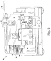
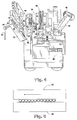
- Cleaver 20 is similar to the prior art cleaver of Figure 1, and generally comprises of a base 22 having an upper surface 24 , a cover plate 26 hingedly attached to base 22 along an edge of surface 24 , a cutting tool (scribing wheel) 28 slidably attached to base 22 , and a hammer or arm 30 pivotally attached to base 22 along an edge of surface 24 opposite plate 26 .
- Surface 24 has a guide ramp or track 32 for receiving a fiber holder 34 . While Figures 3 and 4 depict a holder 34 for a discrete fiber, it is understood that this holder could be replaced with one designed to retain a fiber ribbon.
- the terminal ends of the fibers are supported by two lower pads 36 and 38 mounted on surface 24 and positioned on either side of scribing wheel 28 .
- Two upper pads 40 and 42 attached to cover plate 26 are located to forcibly abut pads 36 and 38 , respectively, when plate 26 is moved to its closed position ( Figure 3). These pads hold the fibers in place, parallel and coplanar. It is thus important that the clamping surfaces of the lower pads themselves be coplanar, and that the upper pads be properly aligned with the lower pads to avoid misalignment of the fibers with respect to scribing wheel 28 .
- a spring-loaded button 44 is also used to secure holder 34 in place during cleaving.
- Scribing wheel 28 is oriented generally perpendicular to the terminal ends of the fibers, and its size and location are such that its upper edge coincides with the plane defined by the upper surfaces of pads 36 and 38 whereby the edge of wheel 28 may contact and score any fibers held by the pads of cleaver 20 .
- Arm 30 has a slotted push member or anvil 46 at its end for cleaving the fibers after they have been scored.
- arm 30 and anvil 46 are such that, when arm 46 is moved downward to its operative position ( Figure 3), anvil 46 is generally located between pads 36 and 38 , and the slot in anvil 46 generally coincides with the line defined by the moving upper edge of scribing wheel 28 , i.e., the slot is preferably centered on this line.
- Figure 3 The dimensions and position of arm 30 and anvil 46 are such that, when arm 46 is moved downward to its operative position ( Figure 3), anvil 46 is generally located between pads 36 and 38 , and the slot in anvil 46 generally coincides with the line defined by the moving upper edge of scribing wheel 28 , i.e., the slot is preferably centered on this line.
- cleaver 20 The primary difference between cleaver 20 and the prior art cleaver of Figure 1 is the provision in cleaver 20 of means for moving one of the upper pads with respect to its corresponding lower pad when plate 26 is in its closed position.
- pad 42 is slidably attached to plate 26 in such a manner that it can move slightly across pad 38 , in a direction generally perpendicular to the terminal ends of the fibers.
- Pad 42 is preferably attached to plate 26 by means of a bar or carriage 48 which slides within a slot 50 in the underside of plate 26 , the slot and carriage forming a dovetail joint.
- Pad 42 is received in a cavity of carriage 48 .
- a plug or stop member 52 is fixed to plate 26 in one end of slot 50 to prevent carriage 48 from completely sliding out through that end of the slot. Stop 52 also serves as a backing for a spring 54 which biases carriage 48 (and pad 42 ) toward the other end of slot 50 (its relaxed position), where a screw 56 passes through plate 26 into slot 50 .
- the tip 58 of screw 56 which abuts one end of carriage 48 , is conical or beveled, and the end of carriage 48 is chamfered, such that clockwise rotation of screw 56 and its resulting downward movement causes carriage 48 to recede as tip 58 moves into forcible contact with the chamfered end of carriage 48 .
- a stop (not shown) may be provided to limit the rotation of screw 56 , thereby limiting movement of pad 42 . In the preferred embodiment, maximum rotation of screw 56 results in pad 42 moving about 30-70 ⁇ m.
- a small rod 60 may be attached to screw 56 to provide a handle to facilitate turning of the screw.
- the resulting end faces of the fibers are disposed at an oblique angle (typically 3-10°) with respect to the fiber axes, as opposed to a right angle, similar to the cleaving operation of Figure 2. It may be noted that, in addition to being angled, the end face of each fiber is helical, rather than flat, but this is merely an incidental result which is ancillary to the primary goal of providing fibers with an angle cleave.
- cleaver 20 The materials of cleaver 20 are not particularly critical, although it is important to provide pads having an appropriate hardness which allows them to firmly grip and twist the fibers.
- the pads are thus preferably formed of an elastomeric material having a Shore A hardness in the range of 50-80.
- the remaining components of cleaver 20 may be formed from any durable material, preferably a metal such as aluminum or stainless steel.
- cleaver 20 Prior to cleaving, however, the fiber(s) must be properly prepared. If the fibers are in the form of a ribbon which is part of a bundled group of ribbons in a cable, then a portion of the cable jacket must be cut back to reveal the ribbons. Most cables have several protective layers, e.g., the ribbons are first surrounded by a thermal wrap, then an inner sheath, then a polyester tape layer, followed by an outer sheath, with one or more intervening layers of strength members (i.e., aramid fibers). Each of these layers must be removed to provide access to the fiber ribbons. Similar steps must be taken to remove the protective layers of a cable having a single discrete fiber.
- strength members i.e., aramid fibers
- the craftsperson may optionally join the discrete fibers in a ribbon format, such as by using the FIBRLOK 2670 multifiber ribbon construction tool sold by Minnesota Mining and Manufacturing Co. (3M--assignee of the present invention; FIBRLOK is a trademark of 3M).
- the terminal end of the ribbon should be cleaned, and the fibers stripped.
- the minimum strip length is the distance from the outside of pad 38 to the outside of pad 42 which, in the preferred embodiment, is about 20 mm.
- Stripping may be simplified by using the multi-fiber stripping tool shown in U.S. Patent No. 4,850,108. This tool strips away the bonding material of the ribbon as well as the buffer coatings on each of the individual fibers. Any debris should be cleaned off the fibers using a lint-free cloth.
- the stripped fibers are then ready for cleaving. They are placed on support surface 24 , either manually or by means of fiber holder 34 , overlying pads 36 and 38 .
- Plate 26 is lowered into its closed position, clamping the fibers at the two locations between pads 36 and 40 , and pads 38 and 42 , respectively.
- the pads should also be clean and free of any debris.
- a visual inspection may confirm that the fibers are properly positioned and taut.
- Handle 60 is moved the desired amount, shifting upper pad 42 and placing each of the fibers under a torsional load.
- the fibers are then scored by sliding scribing wheel 28 forward, and cleaved by pushing anvil 46 against the fibers.
- the craftsperson may inspect the fibers to confirm that the end faces on all fibers are acceptable, i.e., that they are clean cleaves with no spikes. The fiber viewer disclosed in U.S.
- Patent Application Serial No. 07/763,192 may be used for this purpose.
- the fibers may be removed from the cleaver, and inserted into an appropriate connection device, such as the FIBRLOK Multi-Fiber Optical Splice sold by 3M (see U.S. Patent No. 5,151,964).
- an appropriate connection device such as the FIBRLOK Multi-Fiber Optical Splice sold by 3M (see U.S. Patent No. 5,151,964).
- the fibers should be inserted so that the orientation of the angled end faces of one set of fibers complement the orientation of the angled end faces of the other set of fibers, i.e., the end faces of a given pair of fibers to be spliced are preferably parallel to each other when spliced.
- Cleaver 20 present clear advantages over the prior art.
- cleaver 20 greatly simplifies the cleaving process for both single and multiple fibers.
- it is much simpler to turn handle 60 and thereby induce the torsional load than to attach and manipulate the collet of the prior art device of Figure 2.
- cleaver 20 provides a quick and easy method of simultaneously cleaving all of the fibers in a ribbon, and all at the same length.
Landscapes
- Physics & Mathematics (AREA)
- General Physics & Mathematics (AREA)
- Optics & Photonics (AREA)
- Mechanical Coupling Of Light Guides (AREA)
- Perforating, Stamping-Out Or Severing By Means Other Than Cutting (AREA)
- Light Guides In General And Applications Therefor (AREA)
Applications Claiming Priority (2)
| Application Number | Priority Date | Filing Date | Title |
|---|---|---|---|
| US08/038,500 US5395025A (en) | 1993-03-29 | 1993-03-29 | Method and apparatus for angle cleaving ribbon fiber |
| US38500 | 1998-03-10 |
Publications (3)
| Publication Number | Publication Date |
|---|---|
| EP0618466A2 true EP0618466A2 (fr) | 1994-10-05 |
| EP0618466A3 EP0618466A3 (fr) | 1995-10-11 |
| EP0618466B1 EP0618466B1 (fr) | 2001-08-16 |
Family
ID=21900314
Family Applications (1)
| Application Number | Title | Priority Date | Filing Date |
|---|---|---|---|
| EP94104838A Expired - Lifetime EP0618466B1 (fr) | 1993-03-29 | 1994-03-27 | Appareil pour tailler une face terminale oblique au travers d'une portion d'extrémité de fibres d'un ruban de fibres optiques |
Country Status (5)
| Country | Link |
|---|---|
| US (1) | US5395025A (fr) |
| EP (1) | EP0618466B1 (fr) |
| JP (1) | JPH06317711A (fr) |
| DE (1) | DE69427930T2 (fr) |
| ES (1) | ES2159531T3 (fr) |
Cited By (4)
| Publication number | Priority date | Publication date | Assignee | Title |
|---|---|---|---|---|
| WO1998047030A3 (fr) * | 1997-04-14 | 1999-01-28 | Minnesota Mining & Mfg | Systeme de preparation et de connexion de faces terminales de fibres optiques |
| EP0926518A3 (fr) * | 1997-12-19 | 2000-05-03 | Telefonaktiebolaget Lm Ericsson | Un dispositif de fixation de fibre de ruban |
| US6078719A (en) * | 1997-04-14 | 2000-06-20 | 3M Innovative Properties Company | Optical fiber holder |
| EP1972973A2 (fr) | 2002-07-16 | 2008-09-24 | Tyco Electronics Raychem NV | Dispositif pour coupage orienté pour fibre optique |
Families Citing this family (25)
| Publication number | Priority date | Publication date | Assignee | Title |
|---|---|---|---|---|
| AU1521099A (en) * | 1997-11-24 | 1999-06-15 | Corning Incorporated | Fiber array cleaving |
| US6963687B2 (en) * | 1998-09-18 | 2005-11-08 | The Whitaker Corporation | Process for cutting an optical fiber |
| DE19903569A1 (de) * | 1999-01-29 | 2000-08-24 | Siemens Ag | Vorrichtung zum Trennen von mindestens einer lichtleitenden Faser |
| US6695191B1 (en) | 1999-10-08 | 2004-02-24 | Leviton Manufacturing Co., Inc. | Optical fiber cleaver |
| US20020130152A1 (en) * | 2001-03-19 | 2002-09-19 | Amherst Holding Co. | Optical fiber cleaver with traversing mechanism |
| US6628879B2 (en) | 2001-07-26 | 2003-09-30 | Leviton Manufacturing Co., Inc. | Adapter for optical fiber cleaver |
| CN100396411C (zh) * | 2002-08-26 | 2008-06-25 | 日新精密工业株式会社 | 光纤自动切断器 |
| JP4000565B2 (ja) * | 2002-09-06 | 2007-10-31 | 日立金属株式会社 | 光ファイバ切断装置 |
| US7025239B2 (en) | 2002-11-25 | 2006-04-11 | Leviton Manufacturing Co., Inc. | Optical fiber cleaver |
| KR100471083B1 (ko) * | 2002-12-24 | 2005-03-10 | 삼성전자주식회사 | 광섬유 절단장치 |
| US7669744B2 (en) * | 2003-08-04 | 2010-03-02 | 3M Innovative Properties Company | Device and method for cleaving optical fibers |
| JP4424934B2 (ja) * | 2003-08-04 | 2010-03-03 | スリーエム イノベイティブ プロパティズ カンパニー | 光ファイバの切断装置及び切断方法 |
| JP4760208B2 (ja) * | 2005-08-09 | 2011-08-31 | 住友電気工業株式会社 | 光ファイバ保持装置及び光ファイバ融着接続機 |
| JP4775084B2 (ja) * | 2006-04-10 | 2011-09-21 | 住友電気工業株式会社 | コネクタの組立方法 |
| WO2009051918A1 (fr) * | 2007-10-19 | 2009-04-23 | 3M Innovative Properties Company | Coupe-fibre optique sans lame et procédé |
| JP5624604B2 (ja) | 2009-04-17 | 2014-11-12 | スリーエム イノベイティブプロパティズカンパニー | ブレードレス光ファイバ切断工具 |
| US8494331B2 (en) | 2011-07-06 | 2013-07-23 | Go!Foton Holdings, Inc. | Apparatus and method for mass producing optical fiber splice-on connector subunits |
| US8506178B2 (en) | 2011-06-24 | 2013-08-13 | Go!Foton Holdings, Inc. | Mechanical splicer apparatus for fiber optic cables |
| US8506179B2 (en) | 2011-07-21 | 2013-08-13 | Go!Foton Holdings, Inc. | Deformable plastic radially symmetric mechanical splicers and connectors for optical fibers |
| KR101826654B1 (ko) * | 2012-02-20 | 2018-02-07 | 이노 인스트루먼트 (차이나). 인코퍼레이션 | 광섬유 절단기 |
| ES2528335B1 (es) * | 2012-05-11 | 2016-01-07 | Dh Infotech (Wei Hai) Inc. | Recogedor completamente automático de fibra óptica |
| USD745816S1 (en) * | 2013-12-16 | 2015-12-22 | Dh Infotech (Weihai) Inc. | Optical fiber cleaver |
| US9835799B2 (en) * | 2015-04-02 | 2017-12-05 | Textron Innovations Inc. | Loose tube fiber cable adapter and splice-on connector adapter |
| JP6244491B1 (ja) * | 2017-03-06 | 2017-12-06 | 株式会社フジクラ | 光ファイバ切断装置 |
| US20220334326A1 (en) * | 2019-08-30 | 2022-10-20 | Commscope Technologies Llc | Fiber gripping tool |
Family Cites Families (17)
| Publication number | Priority date | Publication date | Assignee | Title |
|---|---|---|---|---|
| US3934773A (en) * | 1973-11-02 | 1976-01-27 | Bell Telephone Laboratories, Incorporated | Method for breaking brittle rods or fibers |
| JPS5426751A (en) * | 1977-08-01 | 1979-02-28 | Nippon Telegr & Teleph Corp <Ntt> | Cutting method and apparatus for optical fiber |
| GB2046242A (en) * | 1979-03-08 | 1980-11-12 | Secr Defence | Fibre optic cleaving tool |
| DE3017873A1 (de) * | 1980-05-09 | 1981-11-12 | Siemens AG, 1000 Berlin und 8000 München | Verfahren und vorrichtung zum trennen von mehreren in einem kabel vereinigten lichtwellenleitern |
| JPS58152212A (ja) * | 1982-03-05 | 1983-09-09 | Nec Corp | 光コネクタ |
| US4695126A (en) * | 1985-02-11 | 1987-09-22 | Dorran Photonics, Incorporated | Method and apparatus for effecting light energy transmission with lessened reflection |
| JPH0778563B2 (ja) * | 1987-11-11 | 1995-08-23 | 株式会社フジクラ | 光フアイバの切断装置 |
| US5024363A (en) * | 1987-06-16 | 1991-06-18 | Fujikura Ltd. | Method and apparatus for cutting an optical fiber |
| JPH0454191Y2 (fr) * | 1987-10-29 | 1992-12-18 | ||
| US4978193A (en) * | 1989-08-24 | 1990-12-18 | Raychem Corporation | Optical fiber connector which provides a high signal return loss |
| CH678980A5 (fr) * | 1989-10-02 | 1991-11-29 | Diamond Sa | |
| JPH03210509A (ja) * | 1990-01-12 | 1991-09-13 | Seiko Giken:Kk | 光コネクタフェルール部材 |
| US5048908A (en) * | 1990-02-13 | 1991-09-17 | At&T Bell Laboratories | Method of producing apparatus comprising a low-reflection optical fiber connection |
| FR2661635B1 (fr) * | 1990-05-03 | 1994-12-09 | Alcatel Fibres Optiques | Dispositif pour couper obliquement une fibre optique. |
| GB2255335B (en) * | 1991-05-02 | 1995-01-25 | Bicc Plc | Optical fibre cleaving |
| FR2689805B1 (fr) * | 1992-04-14 | 1994-06-03 | Boitel Michel | Appareil de coupe oblique d'une ou de plusieurs fibres optiques. |
| DE9310127U1 (de) * | 1993-07-07 | 1993-08-26 | Richard Hirschmann Gmbh & Co, 73728 Esslingen | Vorrichtung für die Herstellung von schrägen Endflächen von Lichtwellenleitern in einem Faserband |
-
1993
- 1993-03-29 US US08/038,500 patent/US5395025A/en not_active Expired - Fee Related
-
1994
- 1994-03-27 ES ES94104838T patent/ES2159531T3/es not_active Expired - Lifetime
- 1994-03-27 EP EP94104838A patent/EP0618466B1/fr not_active Expired - Lifetime
- 1994-03-27 DE DE69427930T patent/DE69427930T2/de not_active Expired - Fee Related
- 1994-03-28 JP JP6057074A patent/JPH06317711A/ja active Pending
Cited By (7)
| Publication number | Priority date | Publication date | Assignee | Title |
|---|---|---|---|---|
| WO1998047030A3 (fr) * | 1997-04-14 | 1999-01-28 | Minnesota Mining & Mfg | Systeme de preparation et de connexion de faces terminales de fibres optiques |
| US6078719A (en) * | 1997-04-14 | 2000-06-20 | 3M Innovative Properties Company | Optical fiber holder |
| US6099392A (en) * | 1997-04-14 | 2000-08-08 | 3M Innovative Properties Company | Optical fiber end-face preparation tool |
| EP1326106A3 (fr) * | 1997-04-14 | 2003-12-10 | Minnesota Mining And Manufacturing Company | Appareil pour la préparation de la face d'extrémité d'une fibre optique |
| EP0926518A3 (fr) * | 1997-12-19 | 2000-05-03 | Telefonaktiebolaget Lm Ericsson | Un dispositif de fixation de fibre de ruban |
| US6337943B1 (en) | 1997-12-19 | 2002-01-08 | Telefonaktiebolaget Lm Ericsson (Publ) | Ribbon fibre fixating device |
| EP1972973A2 (fr) | 2002-07-16 | 2008-09-24 | Tyco Electronics Raychem NV | Dispositif pour coupage orienté pour fibre optique |
Also Published As
| Publication number | Publication date |
|---|---|
| US5395025A (en) | 1995-03-07 |
| DE69427930T2 (de) | 2002-04-04 |
| EP0618466A3 (fr) | 1995-10-11 |
| ES2159531T3 (es) | 2001-10-16 |
| EP0618466B1 (fr) | 2001-08-16 |
| DE69427930D1 (de) | 2001-09-20 |
| JPH06317711A (ja) | 1994-11-15 |
Similar Documents
| Publication | Publication Date | Title |
|---|---|---|
| US5395025A (en) | Method and apparatus for angle cleaving ribbon fiber | |
| KR100913647B1 (ko) | 광섬유의 배향된 절단을 위한 장치 | |
| WO2002004998A1 (fr) | Porte-conducteur de fibre optique, dispositif de connexion par fusion, dispositif de decoupe et procede de connexion de fibre optique | |
| US6079297A (en) | Fiber optic precision linear stripper | |
| JP3996966B2 (ja) | ケーブル被覆取り方法と工具 | |
| ZA200903201B (en) | Optical fibre cleaving device | |
| US20020100552A1 (en) | Apparatus for stripping a coating from an optical fibre | |
| US5382276A (en) | Method and apparatuses for cutting a ribbon of an optical fibers obliquely | |
| US6850686B2 (en) | Machining an insulated optical fiber | |
| JP3745340B2 (ja) | 光ファイバの軸合わせ方法及びその装置、並びに光ファイバの融着接続方法及びその装置 | |
| JPH11248945A (ja) | リボンファイバ固定装置 | |
| JP2001520760A (ja) | 光ファイバホルダおよび端面加工工具 | |
| JP3288899B2 (ja) | 光ファイバ用切断失敗検出機構 | |
| EP0637763A1 (fr) | Dispositif de clivage oblique de fibres optiques | |
| JPH0272305A (ja) | 複数単心光ファイバの一括接続法 | |
| JPH0660967B2 (ja) | 光フアイバの一括融着接続方法 | |
| JPH09127356A (ja) | 光ファイバ接続工具 | |
| JPH041521Y2 (fr) | ||
| JP2000221367A (ja) | 光ファイバ突き合わせ装置 | |
| GB2255335A (en) | Optical fibre cleaving | |
| JPH0477284B2 (fr) | ||
| JPH06201948A (ja) | 光ファイバテープ心線の簡易接続治具 | |
| JPH09243838A (ja) | 裸光ファイバの端末構造 | |
| JP2001154029A (ja) | 光ファイバーの切断装置 | |
| JPH08198636A (ja) | 光ファイバの切断器、融着接続装置及び融着接続方法 |
Legal Events
| Date | Code | Title | Description |
|---|---|---|---|
| PUAI | Public reference made under article 153(3) epc to a published international application that has entered the european phase |
Free format text: ORIGINAL CODE: 0009012 |
|
| AK | Designated contracting states |
Kind code of ref document: A2 Designated state(s): DE ES FR GB IT |
|
| PUAL | Search report despatched |
Free format text: ORIGINAL CODE: 0009013 |
|
| AK | Designated contracting states |
Kind code of ref document: A3 Designated state(s): DE ES FR GB IT |
|
| 17P | Request for examination filed |
Effective date: 19960320 |
|
| 17Q | First examination report despatched |
Effective date: 19990125 |
|
| RTI1 | Title (correction) |
Free format text: DEVICE FOR FORMING AN OBLIQUE CLEAVED END FACE THROUGH THE END PORTION OF THE FIBERS OF AN OPTICAL FIBER RIBBON |
|
| GRAG | Despatch of communication of intention to grant |
Free format text: ORIGINAL CODE: EPIDOS AGRA |
|
| GRAG | Despatch of communication of intention to grant |
Free format text: ORIGINAL CODE: EPIDOS AGRA |
|
| GRAH | Despatch of communication of intention to grant a patent |
Free format text: ORIGINAL CODE: EPIDOS IGRA |
|
| GRAH | Despatch of communication of intention to grant a patent |
Free format text: ORIGINAL CODE: EPIDOS IGRA |
|
| GRAA | (expected) grant |
Free format text: ORIGINAL CODE: 0009210 |
|
| AK | Designated contracting states |
Kind code of ref document: B1 Designated state(s): DE ES FR GB IT |
|
| REF | Corresponds to: |
Ref document number: 69427930 Country of ref document: DE Date of ref document: 20010920 |
|
| REG | Reference to a national code |
Ref country code: ES Ref legal event code: FG2A Ref document number: 2159531 Country of ref document: ES Kind code of ref document: T3 |
|
| ET | Fr: translation filed | ||
| REG | Reference to a national code |
Ref country code: GB Ref legal event code: IF02 |
|
| PG25 | Lapsed in a contracting state [announced via postgrant information from national office to epo] |
Ref country code: GB Free format text: LAPSE BECAUSE OF NON-PAYMENT OF DUE FEES Effective date: 20020327 |
|
| PG25 | Lapsed in a contracting state [announced via postgrant information from national office to epo] |
Ref country code: ES Free format text: LAPSE BECAUSE OF NON-PAYMENT OF DUE FEES Effective date: 20020328 |
|
| PLBE | No opposition filed within time limit |
Free format text: ORIGINAL CODE: 0009261 |
|
| STAA | Information on the status of an ep patent application or granted ep patent |
Free format text: STATUS: NO OPPOSITION FILED WITHIN TIME LIMIT |
|
| 26N | No opposition filed | ||
| PG25 | Lapsed in a contracting state [announced via postgrant information from national office to epo] |
Ref country code: DE Free format text: LAPSE BECAUSE OF NON-PAYMENT OF DUE FEES Effective date: 20021001 |
|
| GBPC | Gb: european patent ceased through non-payment of renewal fee |
Effective date: 20020327 |
|
| PG25 | Lapsed in a contracting state [announced via postgrant information from national office to epo] |
Ref country code: FR Free format text: LAPSE BECAUSE OF NON-PAYMENT OF DUE FEES Effective date: 20021129 |
|
| REG | Reference to a national code |
Ref country code: FR Ref legal event code: ST |
|
| REG | Reference to a national code |
Ref country code: ES Ref legal event code: FD2A Effective date: 20030410 |
|
| PG25 | Lapsed in a contracting state [announced via postgrant information from national office to epo] |
Ref country code: IT Free format text: LAPSE BECAUSE OF NON-PAYMENT OF DUE FEES;WARNING: LAPSES OF ITALIAN PATENTS WITH EFFECTIVE DATE BEFORE 2007 MAY HAVE OCCURRED AT ANY TIME BEFORE 2007. THE CORRECT EFFECTIVE DATE MAY BE DIFFERENT FROM THE ONE RECORDED. Effective date: 20050327 |