EP0619076B1 - Conche - Google Patents
Conche Download PDFInfo
- Publication number
- EP0619076B1 EP0619076B1 EP94103557A EP94103557A EP0619076B1 EP 0619076 B1 EP0619076 B1 EP 0619076B1 EP 94103557 A EP94103557 A EP 94103557A EP 94103557 A EP94103557 A EP 94103557A EP 0619076 B1 EP0619076 B1 EP 0619076B1
- Authority
- EP
- European Patent Office
- Prior art keywords
- compartments
- rotorshaft
- conching
- chocolate
- separating wall
- Prior art date
- Legal status (The legal status is an assumption and is not a legal conclusion. Google has not performed a legal analysis and makes no representation as to the accuracy of the status listed.)
- Expired - Lifetime
Links
- 235000019219 chocolate Nutrition 0.000 claims abstract description 27
- 238000001816 cooling Methods 0.000 claims description 10
- 238000010438 heat treatment Methods 0.000 claims description 5
- 238000009413 insulation Methods 0.000 claims description 3
- 238000007789 sealing Methods 0.000 claims description 3
- 229910000831 Steel Inorganic materials 0.000 claims 1
- 239000000945 filler Substances 0.000 claims 1
- 239000002184 metal Substances 0.000 claims 1
- 239000010959 steel Substances 0.000 claims 1
- 238000005192 partition Methods 0.000 abstract description 21
- 150000001875 compounds Chemical class 0.000 abstract 1
- 244000299461 Theobroma cacao Species 0.000 description 22
- 238000005265 energy consumption Methods 0.000 description 9
- 230000005540 biological transmission Effects 0.000 description 5
- 230000033228 biological regulation Effects 0.000 description 3
- 238000004519 manufacturing process Methods 0.000 description 3
- 238000003860 storage Methods 0.000 description 3
- 230000007423 decrease Effects 0.000 description 2
- 235000013305 food Nutrition 0.000 description 2
- 238000011109 contamination Methods 0.000 description 1
- 230000003247 decreasing effect Effects 0.000 description 1
- 230000000694 effects Effects 0.000 description 1
- 239000000314 lubricant Substances 0.000 description 1
- 238000000034 method Methods 0.000 description 1
- 238000003825 pressing Methods 0.000 description 1
- 230000001105 regulatory effect Effects 0.000 description 1
- 238000005303 weighing Methods 0.000 description 1
- 235000019222 white chocolate Nutrition 0.000 description 1
- 235000019220 whole milk chocolate Nutrition 0.000 description 1
Images

Classifications
-
- A—HUMAN NECESSITIES
- A23—FOODS OR FOODSTUFFS; TREATMENT THEREOF, NOT COVERED BY OTHER CLASSES
- A23G—COCOA; COCOA PRODUCTS, e.g. CHOCOLATE; SUBSTITUTES FOR COCOA OR COCOA PRODUCTS; CONFECTIONERY; CHEWING GUM; ICE-CREAM; PREPARATION THEREOF
- A23G1/00—Cocoa; Cocoa products, e.g. chocolate; Substitutes therefor
- A23G1/04—Apparatus specially adapted for manufacture or treatment of cocoa or cocoa products
- A23G1/16—Circular conches, i.e. rollers being displaced on a closed or circular rolling circuit
-
- A—HUMAN NECESSITIES
- A23—FOODS OR FOODSTUFFS; TREATMENT THEREOF, NOT COVERED BY OTHER CLASSES
- A23G—COCOA; COCOA PRODUCTS, e.g. CHOCOLATE; SUBSTITUTES FOR COCOA OR COCOA PRODUCTS; CONFECTIONERY; CHEWING GUM; ICE-CREAM; PREPARATION THEREOF
- A23G1/00—Cocoa; Cocoa products, e.g. chocolate; Substitutes therefor
- A23G1/04—Apparatus specially adapted for manufacture or treatment of cocoa or cocoa products
- A23G1/12—Chocolate-refining mills, i.e. roll refiners
- A23G1/125—Conches
Definitions
- the invention relates to a conche according to the preamble of claim 1.
- Conches are used to refine chocolate masses, for example after the chocolate mass has been processed on roller mills.
- continuous conches or batch conches with a large volume can be used.
- Small batch conches must be used in the production of small batches, since the conchen trough must be filled to a minimum fill level.
- the object of the invention is now to create a conche that can be optimally used with a small space and investment requirement both in the production of small quantities and large quantities of chocolate mass of different recipes, the expansion with regard to the number of compartments being virtually unlimited and the food regulations are also easy to comply with.
- the tools in each compartment rub and fill the chocolate mass inside. If there is no chocolate mass in a compartment, the tools of this compartment rotate without resistance.
- the advantage of a conche according to the invention is that, for example, in the case of two compartments, the same recipe can be conched either in both compartments or different recipes in both.
- the conche is used like a conche with a large volume and with two recipes with a small quantity, like two conches with half the volume.
- the equipment required for a conche according to the invention is much less than for the prior art. Because not only that savings are made on transmission parts and the space to be provided for them, bearing units and only one drive are only required on both end sides of the trough, the risk of contamination from lubricants being practically eliminated.
- the conche according to the invention enables optimal and versatile utilization of its total or partial capacity both in terms of quantity and over time.
- the entire production process is shortened because different recipes can be refined in different quantities at the same time. This advantage is achieved with a minimal outlay on equipment.
- Another advantage of the conche according to the invention results preferably from the staggered filling of the various compartments over time.
- the chocolate masses in the different compartments are in different viscosity states, which also corresponds to different energy consumption or drive loads.
- the total energy consumption of all compartments is an average of the energy consumption of the individual compartments. During the entire conching time, this mean value is clearly below the maximum possible energy consumption with a single chocolate mass filled at the same time. This is because the energy consumption during conching increases in an initial phase, remains in a maximum range for a short time and then slowly decreases to a minimum value.
- Time-shifted conching processes in the compartments of a conche according to the invention are successively in the range of the maximum energy consumption, so that the total maximum energy consumption is smaller than the sum of the individual maximum energy consumption.
- the rotational frequency of the rotor shafts can essentially be kept at a fixed value or can be regulated depending on the state of the chocolate mass of at least one compartment, or depending on the total energy consumption of all compartments or on the drive power. If necessary, the rotational frequency is increased or decreased as the power decreases or increases, in order to achieve an equalization of the drive power.
- a signal is sent to the motor regulation, which generally contains a processor, which corresponds to the number of compartments filled.
- This signal can either be provided by level sensors assigned to each compartment (e.g. an ultrasonic range finder attached to the top), but expediently by a corresponding hand switch for entering the number of compartments in operation or by a switch connected to the locking device for the respective outlet opening of each compartment be delivered.
- a timer is expediently connected downstream of this switch, the time constant of which corresponds to the time which elapses from the opening of the outlet opening to the complete (or at least partial) emptying of the compartment which is in the state of emptying.
- the conche preferably has an overall length of the conch trough which is significantly larger than the depth and the width of the trough.
- openings for the at least one rotor shaft are provided in the partition walls. Since the rotor shaft can be deflected transversely to the axis of rotation under load, the openings must be large enough so that there is no wear due to friction between the rotor shaft and the edge of the opening. A storage of the shaft on the partition walls leads to unnecessary technical problems due to the multiple storage and the bearing seal against the chocolate mass.
- the conche according to the invention therefore does not provide any bearings, but only seals in such a way that chocolate mass cannot pass through the openings in the partition walls.
- Disc springs are preferably used, which bear sealingly on the one hand on the dividing wall and on the other hand on a pressure ring seated tightly on the rotor shaft.
- the plate springs are preferably attached to the partition wall and run with their connection area on a sliding area of the pressure ring which is essentially perpendicular to the axis of rotation.
- the radial sliding area is so large that the connection area lies sealingly on the sliding area even with a maximum shaft movement transverse to the axis of rotation.
- any other seals can also be provided. They have to enable a sufficient seal without high wear and allow the shaft deflection transverse to the axis.
- the seals can be placed on either one or both sides of each partition.
- cooling or heating circuits are preferably provided.
- a cavity for a cooling or heating medium is provided at least in the trough wall area of each compartment.
- a cavity is also provided in each partition on both sides against the adjoining compartments, which cavity is connected to the cooling or heating circuit of the associated compartment. This allows the temperature of the total chocolate mass of each compartment to be kept within a desired range.
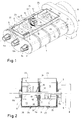
- rotor shaft 1 essentially comprises an elongated trough 1 with lateral end faces 2 and 3 and with at least one rotor shaft 4 arranged in the longitudinal direction of the trough.
- Three parallel rotor shafts 4a, 4b and 4c are preferably provided with conching tools 5.
- 2.3 bearing units 6a, 6b, 6c and 7a, 7b, 7c are provided on the lateral trough surfaces.
- the rotor shafts are driven by a drive 8 via a transmission device 9.
- the trough 1 is divided into at least 2, but preferably 4 compartments 13, 14, 15 and 16 by at least one, but preferably by three partition walls 10, 11 and 12 arranged transversely to the rotor axis of rotation. Conching tools 5 attached to the rotor shafts are provided in each of the compartments 13-16.
- Each partition wall has a passage opening 17 for each rotor shaft, which is selected to be large enough that there is free space for transverse movements of the rotor shaft 4.
- seals 18 are provided, which are preferably designed as disc springs that are pressed against the respective partition 10, 11, 12 by a pressure ring 19.
- the embodiment of the conche according to FIG. 2 provides a partition 10 and thus 2 compartments 13, 14.
- the plate spring 18 provided for sealing the shaft 4b in the passage opening 17 is firmly connected to the partition wall 10 by a holder 20.
- the side 21 of the pressure ring 19 facing the partition 10 is designed as a sliding region 21.
- This sliding area 21 is so large radially that the plate spring 18 lies on the sliding area 21 in a sealing manner even with a maximum wave movement transverse to the axis of rotation.
- any other seals that allow a sufficient seal without high wear and allow the shaft to run sideways can also be provided.
- the seals can be arranged on only one or on both sides of the partition 10.
- Each compartment has a filling opening 22, 23 preferably arranged at the top (according to FIG. 1: also 24, 25) and an outlet opening 26, 27 preferably located at the deepest point of each compartment.
- the chocolate mass can also be filled through the filling openings 22, 23 when the rotor shaft 4 is rotating. As soon as the desired conching time or chocolate quality is reached in a compartment 13, 14, the chocolate mass of this compartment can be discharged or pumped out through the corresponding outlet opening 26, 27.
- a circuit for a cooling or heating medium is optionally provided.
- a cavity 30, 31 is provided in a wall 1a delimiting the trough 1 for each compartment 13, 14.
- the cooling circuit of the compartment 13 also comprises a cavity 32 in the end wall 2 and a cavity 33 in the partition wall 10.
- cavities 31, 34 in the partition wall 10 and 35 in the end wall 3 belong to the cooling circuit of the compartment 14.
- An insulation layer is optionally provided in the cavities 33 and 34 of the partition 10, so that the circuits do not essentially influence one another.
- FIG. 3 An embodiment according to FIG. 3 provides that the at least two, but preferably four compartments 13-16 are formed by fully formed troughs lined up.
- two partitions 10a, 10b; 11a, 11b; 12a, 12b are preferably arranged at a distance forming an air gap 37.
- Each trough or compartment 13-16 preferably also comprises a cooling circuit.
- the cooling cavities are designated for the compartments 13 and 14 with the reference numerals 30-35.
- the air gap 37 between the compartments 13 and 14 acts as an insulation layer between the cavities 33 and 34.
- the seals between the rotor shafts 4 and the partition walls 10a-12b are made by means of disc springs 18, which are pressed against at least one partition wall 10a-12b by pressing rings 19.
- a frame 38 holding the compartments 13-16 or the troughs, to which the trough walls are attached is optionally provided.
- a drive motor 8a and a belt drive 8b are also attached to the frame 38.
- a transmission device 9, in particular a transmission, is arranged between the belt drive 8b and the at least one rotor shaft 4.
Landscapes
- Life Sciences & Earth Sciences (AREA)
- Chemical & Material Sciences (AREA)
- Engineering & Computer Science (AREA)
- Food Science & Technology (AREA)
- Polymers & Plastics (AREA)
- Confectionery (AREA)
- Vending Machines For Individual Products (AREA)
- Packging For Living Organisms, Food Or Medicinal Products That Are Sensitive To Environmental Conditiond (AREA)
- Peptides Or Proteins (AREA)
- Cosmetics (AREA)
- Medicines That Contain Protein Lipid Enzymes And Other Medicines (AREA)
Claims (4)
- Conche destinée au conchage discontinu de pâtes de chocolat, comprenant une cuve et au moins un arbre de rotor (4a, 4b, 4c) sur lequel sont fixés des outils (5), qui en font saillie radialement, et qui sont situés à distance radiale de cet arbre de rotor (4a, 4b, 4c) pour lequel est prévu un dispositif d'entraînement (8) commun, au moins deux compartiments (13-16), avec chacun au moins une ouverture de remplissage (22-25) et chacun au moins une ouverture de sortie, étant prévus pour le broyage et le malaxage séparés de pâtes de chocolat, de façon telle, qu'il ne puisse pas se produire d'échange de pâte de chocolat entre les compartiments (13-16), mais que la pâte de chocolat puisse être évacuée ou extraite par pompage, par l'intermédiaire de l'ouverture de sortie (26, 27) considérée, après la durée de traitement appropriée, adaptée à la recette considérée et à la vitesse de rotation, caractérisée en ce quea) ledit au moins un arbre de rotor (4) s'étend horizontalement au travers des compartiments (13-16), les outils de conchage (5) de tous les compartiments (13-16) étant fixés au dit au moins un arbre de rotor commun (4a, 4b, 4c), en ce queb) ledit au moins un arbre de rotor (4a, 4b, 4c) est monté sur paliers uniquement aux deux extrémités de cuve, en ce quec) les compartiments sont séparés les uns des autres par au moins une cloison de séparation (10, 11, 12) disposée transversalement à un arbre de rotor (4), une ouverture de passage (17) étant agencée pour chaque arbre de rotor (4a, 4b, 4c) dans ladite au moins une cloison de séparation (10, 11, 12), et en ce qu'd) à chaque ouverture de passage (17) est associé au moins un joint d'étanchéité (18, 19) comportant un frotteur d'étanchéité, de façon telle que l'arbre de rotor (4a, 4b, 4c) oscillant sous charge, puisse se déplacer à l'intérieur des ouvertures de passage (17), transversalement à l'axe de rotation de l'arbre de rotor (4).
- Conche selon la revendication 1, caractérisée en ce que le joint d'étanchéité (18, 19) comprend une rondelle-ressort (18), de préférence en métal, notamment en acier, qui, de préférence, est fixée sur la cloison de séparation (10, 11, 12), et qui forme un joint d'étanchéité à frottement sur une surface de frottement disposée transversalement à l'axe de rotation et faisant partie d'un anneau de pression (19) monté sur l'arbre (4) et pressant la rondelle-ressort (18) contre la cloison de séparation (10, 11, 12), en permettant aussi bien une rotation de l'arbre qu'un déport de l'arbre transversalement à l'axe de rotation.
- Conche selon la revendication 1 ou 2, caractérisée en ce qu'au moins deux compartiments (13-16) ont leur propre circuit de refroidissement ou de chauffage (30-35), et en ce que de préférence entre au moins deux compartiments à circuits de refroidissement séparés, est prévue une couche d'isolation dans la cloison de séparation traversée par l'arbre de rotor commun (4a, 4b, 4c).
- Conche selon l'une des revendications précédentes, caractérisée en ce qu'entre au moins deux compartiments (13-16) se raccordant l'un à l'autre, deux cloisons de séparation (10a, 10b; 11a, 11b; 12a, 12b) traversées par l'arbre de rotor commun (4a, 4b, 4c), sont agencées de préférence à une distance l'une de l'autre formant un interstice (37), et les deux cloisons de séparation (10a, 10b; 11a, 11b; 12a, 12b) sont reliées l'une à l'autre par une pièce tubulaire (36), de préférence conique, de façon telle que ledit au moins un arbre de rotor (4) passe au travers de cette pièce tubulaire (36).
Applications Claiming Priority (2)
| Application Number | Priority Date | Filing Date | Title |
|---|---|---|---|
| DE4310805A DE4310805A1 (de) | 1993-04-06 | 1993-04-06 | Conche und Verfahren zum Betrieb einer solchen |
| DE4310805 | 1993-04-06 |
Publications (2)
| Publication Number | Publication Date |
|---|---|
| EP0619076A1 EP0619076A1 (fr) | 1994-10-12 |
| EP0619076B1 true EP0619076B1 (fr) | 1997-05-14 |
Family
ID=6484545
Family Applications (1)
| Application Number | Title | Priority Date | Filing Date |
|---|---|---|---|
| EP94103557A Expired - Lifetime EP0619076B1 (fr) | 1993-04-06 | 1994-03-09 | Conche |
Country Status (6)
| Country | Link |
|---|---|
| US (1) | US5450786A (fr) |
| EP (1) | EP0619076B1 (fr) |
| JP (1) | JPH078172A (fr) |
| AT (1) | ATE152882T1 (fr) |
| DE (2) | DE4310805A1 (fr) |
| ES (1) | ES2102709T3 (fr) |
Families Citing this family (13)
| Publication number | Priority date | Publication date | Assignee | Title |
|---|---|---|---|---|
| DE4326075A1 (de) * | 1993-08-04 | 1995-02-09 | Callebaut Nv | Vorrichtung zum Conchieren von Schokolademasse |
| US5743640A (en) * | 1996-02-06 | 1998-04-28 | Crossley; Jimmy L. | Ice cream twisting apparatus |
| DE19623206B4 (de) * | 1996-06-11 | 2007-12-13 | Richard Frisse Gmbh | Verfahren zum Veredeln von Schokolademasse |
| DE19637098B4 (de) * | 1996-09-12 | 2009-03-19 | Richard Frisse Gmbh | Vorrichtung zum Mischen und/oder Verfeinern von Schokolademassen |
| US6129008A (en) * | 1996-09-12 | 2000-10-10 | Richard Frisse Gmbh | Apparatus for mixing and refining a chocolate mass |
| DK0872187T3 (da) * | 1997-04-17 | 1999-12-13 | Aasted Mikroverk Aps | Apparat til kontinuerlig temperering af gennemstrømmende kakaosmørholdig eller anden fedtholdig, chokoladelignende masse |
| US6095035A (en) * | 1998-12-30 | 2000-08-01 | Lyco Manufacturing, Inc. | Dual drum food processor |
| US6694867B1 (en) * | 2003-03-31 | 2004-02-24 | Freezing Machines, Inc. | Scraper device and scraper system |
| BRPI0400056B1 (pt) * | 2004-02-11 | 2017-03-21 | Meller Equipamentos E Tecnologia Indústria E Comércio Ltda | máquina tipo concha, instalação e processo para fabricação de massa de chocolate |
| US7095954B2 (en) * | 2004-09-17 | 2006-08-22 | Michel Esnault | Chocolate fountain apparatus with output port |
| IT1399691B1 (it) * | 2010-03-30 | 2013-04-26 | Soremartec Sa | Metodo per la preparazione di un semilavorato dolciario, ad esempio tipo cioccolato o similare |
| DE102017001784B4 (de) * | 2017-02-24 | 2020-12-31 | Netzsch Feinmahltechnik Gmbh | Conchiervorrichtung und Verfahren zum Conchieren einer Produktmasse |
| DE102017120912A1 (de) * | 2017-09-11 | 2019-03-14 | Rinsch Edelstahlverarbeitung Gmbh | Verfahren und Vorrichtung zur Herstellung eines Kakaoprodukts oder Schokoladenprodukts |
Family Cites Families (15)
| Publication number | Priority date | Publication date | Assignee | Title |
|---|---|---|---|---|
| US1658379A (en) * | 1922-06-14 | 1928-02-07 | J M Lehmann Company Inc | Chocolate machine |
| US2035863A (en) * | 1930-05-27 | 1936-03-31 | Fred S Carver | Machine for finishing chocolate and the like |
| US3216706A (en) * | 1963-08-21 | 1965-11-09 | Baker Perkins Inc | Continuous mixing machine |
| GB1261909A (en) * | 1968-07-24 | 1972-01-26 | Cadbury Bros Ltd | A method of, and means for manufacturing chocolate |
| US3570569A (en) * | 1969-05-05 | 1971-03-16 | Hobart Mfg Co | Food mixing machine |
| US3663231A (en) * | 1970-11-17 | 1972-05-16 | Alfred George Tourell | Process of liquifying and conching refined chocolate and an apparatus for performing the process |
| US3682086A (en) * | 1970-11-18 | 1972-08-08 | Werner & Pfleiderer | Device for producing a mass of chocolate |
| US3638920A (en) * | 1970-11-27 | 1972-02-01 | Ramsey H Davis | Material-mixing apparatus |
| DD108451A1 (fr) * | 1972-11-23 | 1974-09-20 | ||
| FR2550922A1 (fr) * | 1983-08-26 | 1985-03-01 | Creusot Loire | Procede et installation de preparation d'une pate de chocolat |
| US4630930A (en) * | 1984-09-04 | 1986-12-23 | Amf Union Machinery Inc. | High speed batch mixer |
| US4733607A (en) * | 1985-10-07 | 1988-03-29 | Star Leonard J | Food processing machine |
| DE4029037A1 (de) * | 1990-09-13 | 1992-03-19 | Buehler Ag | Verfahren und vorrichtung zum betrieb einer conche |
| US5083506A (en) * | 1991-03-06 | 1992-01-28 | Blentech Corporation | Continuous compartmented mixer |
| ATE166536T1 (de) * | 1991-05-02 | 1998-06-15 | Frisse Richard Maschf | Conche |
-
1993
- 1993-04-06 DE DE4310805A patent/DE4310805A1/de not_active Withdrawn
-
1994
- 1994-03-09 DE DE59402710T patent/DE59402710D1/de not_active Expired - Fee Related
- 1994-03-09 EP EP94103557A patent/EP0619076B1/fr not_active Expired - Lifetime
- 1994-03-09 ES ES94103557T patent/ES2102709T3/es not_active Expired - Lifetime
- 1994-03-09 AT AT94103557T patent/ATE152882T1/de not_active IP Right Cessation
- 1994-03-25 US US08/217,950 patent/US5450786A/en not_active Expired - Lifetime
- 1994-04-01 JP JP6065180A patent/JPH078172A/ja not_active Withdrawn
Also Published As
| Publication number | Publication date |
|---|---|
| EP0619076A1 (fr) | 1994-10-12 |
| ES2102709T3 (es) | 1997-08-01 |
| ATE152882T1 (de) | 1997-05-15 |
| DE59402710D1 (de) | 1997-06-19 |
| JPH078172A (ja) | 1995-01-13 |
| DE4310805A1 (de) | 1994-10-13 |
| US5450786A (en) | 1995-09-19 |
Similar Documents
| Publication | Publication Date | Title |
|---|---|---|
| EP0619076B1 (fr) | Conche | |
| DE2536063C3 (de) | Temperiermaschine für kakaobutterhaltige und ähnliche fetthaltige Massen, insbesondere Schokolademassen | |
| EP0289849B1 (fr) | Procédé et appareil de préparation en continu de masses contenant du beurre de cacao ou des graisses analogues à mettre en oeuvre | |
| DE4433039B4 (de) | Vorrichtungen zum Bearbeiten von Dispersionen | |
| EP0518025B1 (fr) | Conche | |
| EP3473107B1 (fr) | Dispositif et procédé de traitement et de transformation du chocolat ainsi qu'utilisation d'une machine universelle lors dudit procédé | |
| DE3642330C2 (fr) | ||
| DE69005433T2 (de) | Mühle zur herstellung einer suspension bestehend aus festen teilchen in einem fetten träger. | |
| EP0951834B1 (fr) | Appareil de préparation et mise en oeuvre de masses contenant du cacao ou des graisses analogues | |
| EP0677010A1 (fr) | Element de machine rotatif, en particulier rotor d'une helice de navire cycloidale | |
| DE2341639C3 (de) | Verfahren und Vorrichtung zum Herstellen von Schokoladenmassen | |
| EP0439684A1 (fr) | Presse à poinçonner | |
| EP0997077A2 (fr) | Appareil pour le conditionnement thermique continu de masses au beurre de cacao ou autre graisse analogues en vue de leur mise en oeuvre | |
| DE2756907A1 (de) | Schmelzmischer | |
| CH702882A2 (de) | Vorrichtung und Verfahren zum kontinuierlichen Aufbereiten von Mahlgut und Massen. | |
| DE2346691A1 (de) | Vorrichtung zum aufbereiten von pulverfoermigen thermoplastischen kunststoffen | |
| DE2154059A1 (de) | Ruehrwerksmuehle zum feinstmahlen und homogenisieren von kakaomasse | |
| EP0914773A1 (fr) | Appareil de traitement de masses contenant du beurre de cacao ou une graisse analogue, en particulier des masses de chocolat | |
| DE102020134349B3 (de) | Temperiermaschine mit feststehender Trennscheibe | |
| DE2007309C3 (de) | Vorrichtung zum Mischen oder Trocknen eines oder mehrerer pulver-, granulat- oder pastenförmiger Stoffe | |
| DE2223792A1 (de) | Vorrichtung zum mischen und kneten, insbesondere von schokoladenmasse | |
| DE2264177C2 (de) | Maische zur Behandlung einer Füllmasse in der Zuckerindustrie | |
| DE3400452C2 (fr) | ||
| DE1073287B (de) | Maschine zur temperierung von schokoladen- oder ähnlichen fetthaltigen massen des süsswarengewerbes | |
| DE1782115C3 (de) | Maschine zum Mischen und Aufbereiten von pulverigen, körnigen od. kleinstückigen Stoffen |
Legal Events
| Date | Code | Title | Description |
|---|---|---|---|
| PUAI | Public reference made under article 153(3) epc to a published international application that has entered the european phase |
Free format text: ORIGINAL CODE: 0009012 |
|
| 17P | Request for examination filed |
Effective date: 19940811 |
|
| AK | Designated contracting states |
Kind code of ref document: A1 Designated state(s): AT BE CH DE DK ES FR GB GR IE IT LI LU NL PT SE |
|
| K1C1 | Correction of patent application (title page) published |
Effective date: 19941012 |
|
| 17Q | First examination report despatched |
Effective date: 19940219 |
|
| GRAG | Despatch of communication of intention to grant |
Free format text: ORIGINAL CODE: EPIDOS AGRA |
|
| GRAH | Despatch of communication of intention to grant a patent |
Free format text: ORIGINAL CODE: EPIDOS IGRA |
|
| GRAH | Despatch of communication of intention to grant a patent |
Free format text: ORIGINAL CODE: EPIDOS IGRA |
|
| ITF | It: translation for a ep patent filed | ||
| GRAA | (expected) grant |
Free format text: ORIGINAL CODE: 0009210 |
|
| RAP1 | Party data changed (applicant data changed or rights of an application transferred) |
Owner name: RICHARD FRISSE GMBH |
|
| AK | Designated contracting states |
Kind code of ref document: B1 Designated state(s): AT BE CH DE DK ES FR GB GR IE IT LI LU NL PT SE |
|
| PG25 | Lapsed in a contracting state [announced via postgrant information from national office to epo] |
Ref country code: NL Free format text: LAPSE BECAUSE OF FAILURE TO SUBMIT A TRANSLATION OF THE DESCRIPTION OR TO PAY THE FEE WITHIN THE PRESCRIBED TIME-LIMIT Effective date: 19970514 Ref country code: GR Free format text: LAPSE BECAUSE OF FAILURE TO SUBMIT A TRANSLATION OF THE DESCRIPTION OR TO PAY THE FEE WITHIN THE PRESCRIBED TIME-LIMIT Effective date: 19970514 Ref country code: FR Effective date: 19970514 Ref country code: DK Effective date: 19970514 |
|
| REF | Corresponds to: |
Ref document number: 152882 Country of ref document: AT Date of ref document: 19970515 Kind code of ref document: T |
|
| REG | Reference to a national code |
Ref country code: CH Ref legal event code: NV Representative=s name: BUEHLER AG Ref country code: CH Ref legal event code: EP |
|
| REF | Corresponds to: |
Ref document number: 59402710 Country of ref document: DE Date of ref document: 19970619 |
|
| GBT | Gb: translation of ep patent filed (gb section 77(6)(a)/1977) |
Effective date: 19970613 |
|
| REG | Reference to a national code |
Ref country code: ES Ref legal event code: FG2A Ref document number: 2102709 Country of ref document: ES Kind code of ref document: T3 |
|
| PG25 | Lapsed in a contracting state [announced via postgrant information from national office to epo] |
Ref country code: SE Effective date: 19970814 Ref country code: PT Effective date: 19970814 |
|
| NLV1 | Nl: lapsed or annulled due to failure to fulfill the requirements of art. 29p and 29m of the patents act | ||
| EN | Fr: translation not filed | ||
| PG25 | Lapsed in a contracting state [announced via postgrant information from national office to epo] |
Ref country code: LU Free format text: LAPSE BECAUSE OF NON-PAYMENT OF DUE FEES Effective date: 19980309 Ref country code: AT Free format text: LAPSE BECAUSE OF NON-PAYMENT OF DUE FEES Effective date: 19980309 |
|
| PLBE | No opposition filed within time limit |
Free format text: ORIGINAL CODE: 0009261 |
|
| STAA | Information on the status of an ep patent application or granted ep patent |
Free format text: STATUS: NO OPPOSITION FILED WITHIN TIME LIMIT |
|
| PG25 | Lapsed in a contracting state [announced via postgrant information from national office to epo] |
Ref country code: IE Free format text: LAPSE BECAUSE OF NON-PAYMENT OF DUE FEES Effective date: 19980330 |
|
| PG25 | Lapsed in a contracting state [announced via postgrant information from national office to epo] |
Ref country code: BE Free format text: LAPSE BECAUSE OF NON-PAYMENT OF DUE FEES Effective date: 19980331 |
|
| REG | Reference to a national code |
Ref country code: IE Ref legal event code: FD4D Ref document number: 73942 Country of ref document: IE |
|
| 26N | No opposition filed | ||
| BERE | Be: lapsed |
Owner name: RICHARD FRISSE G.M.B.H. Effective date: 19980331 |
|
| REG | Reference to a national code |
Ref country code: CH Ref legal event code: NV Representative=s name: BUECHEL, VON REVY & PARTNER |
|
| REG | Reference to a national code |
Ref country code: CH Ref legal event code: NV Representative=s name: BUEHLER AG PATENTABTEILUNG |
|
| REG | Reference to a national code |
Ref country code: GB Ref legal event code: IF02 |
|
| PGFP | Annual fee paid to national office [announced via postgrant information from national office to epo] |
Ref country code: CH Payment date: 20030210 Year of fee payment: 10 |
|
| PGFP | Annual fee paid to national office [announced via postgrant information from national office to epo] |
Ref country code: GB Payment date: 20030226 Year of fee payment: 10 |
|
| PGFP | Annual fee paid to national office [announced via postgrant information from national office to epo] |
Ref country code: ES Payment date: 20030321 Year of fee payment: 10 |
|
| PG25 | Lapsed in a contracting state [announced via postgrant information from national office to epo] |
Ref country code: GB Free format text: LAPSE BECAUSE OF NON-PAYMENT OF DUE FEES Effective date: 20040309 |
|
| PG25 | Lapsed in a contracting state [announced via postgrant information from national office to epo] |
Ref country code: ES Free format text: LAPSE BECAUSE OF NON-PAYMENT OF DUE FEES Effective date: 20040310 |
|
| PG25 | Lapsed in a contracting state [announced via postgrant information from national office to epo] |
Ref country code: LI Free format text: LAPSE BECAUSE OF NON-PAYMENT OF DUE FEES Effective date: 20040331 Ref country code: CH Free format text: LAPSE BECAUSE OF NON-PAYMENT OF DUE FEES Effective date: 20040331 |
|
| GBPC | Gb: european patent ceased through non-payment of renewal fee | ||
| REG | Reference to a national code |
Ref country code: CH Ref legal event code: PL |
|
| PG25 | Lapsed in a contracting state [announced via postgrant information from national office to epo] |
Ref country code: IT Free format text: LAPSE BECAUSE OF NON-PAYMENT OF DUE FEES;WARNING: LAPSES OF ITALIAN PATENTS WITH EFFECTIVE DATE BEFORE 2007 MAY HAVE OCCURRED AT ANY TIME BEFORE 2007. THE CORRECT EFFECTIVE DATE MAY BE DIFFERENT FROM THE ONE RECORDED. Effective date: 20050309 |
|
| REG | Reference to a national code |
Ref country code: ES Ref legal event code: FD2A Effective date: 20040310 |
|
| PGFP | Annual fee paid to national office [announced via postgrant information from national office to epo] |
Ref country code: DE Payment date: 20050831 Year of fee payment: 12 |
|
| PG25 | Lapsed in a contracting state [announced via postgrant information from national office to epo] |
Ref country code: DE Free format text: LAPSE BECAUSE OF NON-PAYMENT OF DUE FEES Effective date: 20061003 |