EP0619103A1 - Versteifungselement - Google Patents
Versteifungselement Download PDFInfo
- Publication number
- EP0619103A1 EP0619103A1 EP93202725A EP93202725A EP0619103A1 EP 0619103 A1 EP0619103 A1 EP 0619103A1 EP 93202725 A EP93202725 A EP 93202725A EP 93202725 A EP93202725 A EP 93202725A EP 0619103 A1 EP0619103 A1 EP 0619103A1
- Authority
- EP
- European Patent Office
- Prior art keywords
- gripping member
- base member
- support
- stay
- hardness
- Prior art date
- Legal status (The legal status is an assumption and is not a legal conclusion. Google has not performed a legal analysis and makes no representation as to the accuracy of the status listed.)
- Withdrawn
Links
Images



Classifications
-
- A—HUMAN NECESSITIES
- A61—MEDICAL OR VETERINARY SCIENCE; HYGIENE
- A61F—FILTERS IMPLANTABLE INTO BLOOD VESSELS; PROSTHESES; DEVICES PROVIDING PATENCY TO, OR PREVENTING COLLAPSING OF, TUBULAR STRUCTURES OF THE BODY, e.g. STENTS; ORTHOPAEDIC, NURSING OR CONTRACEPTIVE DEVICES; FOMENTATION; TREATMENT OR PROTECTION OF EYES OR EARS; BANDAGES, DRESSINGS OR ABSORBENT PADS; FIRST-AID KITS
- A61F5/00—Orthopaedic methods or devices for non-surgical treatment of bones or joints; Nursing devices ; Anti-rape devices
- A61F5/01—Orthopaedic devices, e.g. long-term immobilising or pressure directing devices for treating broken or deformed bones such as splints, casts or braces
- A61F5/02—Orthopaedic corsets
- A61F5/028—Braces for providing support to the lower back, e.g. lumbo sacral supports
-
- A—HUMAN NECESSITIES
- A61—MEDICAL OR VETERINARY SCIENCE; HYGIENE
- A61F—FILTERS IMPLANTABLE INTO BLOOD VESSELS; PROSTHESES; DEVICES PROVIDING PATENCY TO, OR PREVENTING COLLAPSING OF, TUBULAR STRUCTURES OF THE BODY, e.g. STENTS; ORTHOPAEDIC, NURSING OR CONTRACEPTIVE DEVICES; FOMENTATION; TREATMENT OR PROTECTION OF EYES OR EARS; BANDAGES, DRESSINGS OR ABSORBENT PADS; FIRST-AID KITS
- A61F5/00—Orthopaedic methods or devices for non-surgical treatment of bones or joints; Nursing devices ; Anti-rape devices
- A61F5/01—Orthopaedic devices, e.g. long-term immobilising or pressure directing devices for treating broken or deformed bones such as splints, casts or braces
- A61F5/02—Orthopaedic corsets
- A61F5/026—Back straightening devices with shoulder braces to force back the shoulder to obtain a correct curvature of the spine
Definitions
- This invention related generally to support stays and more particularly to a dual durometer support stay for use with an article to be worn by a person.
- Support stays have been utilized in a variety of articles, such as wrist supports, ankle braces, and back supports, as well as many other similar and related products.
- the function of the support has been to provide added rigidity for the article with which it is used.
- These stays have been made from a variety of materials.
- a back support such as those disclosed in U.S. Patent Nos. 5,040,524 and 5,148,549.
- the stays are enclosed in a pocket.
- these back supports have a material which has a rubber texture over the stay pockets so that the support will stay in position on the wearer. It can be seen that the stays have two functional and performance characteristics. The first is that the stainless steel stays give vertical spinal support and prevents the back support from gathering and "rolling over” as the support moves around the body. The second is the grabbing or anti-skid properties of the rubber material over the stay pockets.
- the present invention addresses the drawbacks of the prior art and provides for an improved support stay which may be incorporated in articles to be worn by a person.
- the invention is a support stay for use with an article to be worn by a person.
- the article has an outer surface and inner surface.
- the inner surface is proximate the person when the article is worn.
- the stay includes a base member having a first hardness.
- the first hardness is sufficient to provide a required rigidity for providing support.
- a gripping member is operatively connected to the base member.
- the gripping member has a second hardness which is softer than the first hardness. The gripping member, when attached to the inner surface of the article, provides a non-slip surface against the person wearing the article to keep the article in position.
- the base member and gripping member are co-extruded plastic members and the base is constructed of a polypropylene material and the gripping member is a mixture of polypropylene and rubber. Further, in a preferred embodiment, the base member has a curved cross-section and a plurality of ribs for additional rigidity and a gripping enhancement means is operatively connected to the gripping member.
- the invention is a back support for providing abdominal and lumbosacral support as needed by the wearer.
- the back support includes a waistband of a construction having a limited amount of stretch, the waistband having first and second ends and inner and outer surfaces. Also provided is a means for releasably connecting the first end to the second end so that the waistband surrounds a wearer's lower back.
- An elastic band is operatively connected to the outer surface of the waistband.
- the elastic band has first and second ends releasably connected to the outer surface so as to be easily moved between an unstretched and a stretched position.
- a plurality of support stays are operatively connected to the waistband and positioned on the inner surface.
- the stay includes a base member having a first hardness.
- the first hardness is sufficient to provide a required rigidity for providing support.
- a gripping member is operatively connected to the base member and the gripping member has a second hardness which is softer than the first hardness. The gripping member provides a non-slip surface against the person wearing the back support to keep the back support in position on the wearer.
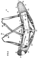
- the back support 10 includes a waistband 11 having a left half 12 and a right half 13. While this is referred to as a waistband, it is understood that the waistband 11 is designed to rest below the navel and accordingly is not defined as being literally a band around the waist, but also may be below the waist.
- a piece of fabric 14, is cut to the size of the entire waistband 11.
- the fabric 14 may be made of either a stretchable or unstretchable fabric.
- a stretchable material such as spandex
- a suitable material such as spandex
- any suitable material such as apex
- a ribbing or binding 18 is stitched around the periphery of the entire waistband 11.
- a loop fabric 19 is stitched to the outside of the right half 13 and a loop fabric 20 is stitched to the outside of the left half 12.
- a hook material 21 is secured by stitching.
- the hook material 21 and loop fabric 19 and 20 may be of any type well-known in the industry which would form a hook and loop type fastener such as Velcro brand.
- the fabric 14 may be somewhat stretchable, however, the fabrics 19 and 20 are substantially non-stretchable.
- the fabric 14 may be suitable material such as the made stretchable Spandex® material.
- the binding 18 may be made of a suitable material such as tricot.
- the overall waistband will have some stretchability. For instance, with a waistband 11 having an overall length of approximately 42 inches, the waistband 11 may expand from 1/2 to 3 inches and preferably from 1-1/2 to 2 inches.
- the waistband 11 has a top edge 12a and 13a and a bottom edge 12b and 13b.
- the right half 12 and the left half 13 form a generally V-shaped waistband 11.
- each half 12 and 13 form an angle of approximately 13° with a horizontal line although in other embodiments there may be no angle.
- Adjustable suspenders, generally designated as 25, are secured to the top edge 12a and 13a of the waistband 11.
- the suspenders 25 may be of any type well known in the art and have shoulder pads 60. Also, the suspenders may be detachable.
- the waistband 11 may have a fibrous material laminated thereto to allow heat and moisture to be transferred away from the body of the wearer.
- a suitable fabric may be a CoolmaxTM fabric by DuPont. The fabric is simply laminated to the waistband 11 such that the fabric is adjacent the wearer of the body.
- the fabric (Coolmax) may be used in place of the Spandex® material forming the waistband 11.
- a four inch wide elastic band designated generally as 30, has a top four inch band 31 and a bottom four inch band 32.
- the top band 31 is generally rectangular but has a slight V-shape and the bottom band 32 has more of a V-shape.
- the bands 31 and 32 are connected to each other at their ends and at the left end of bands 31 and 32 are connected by a vinyl piece 33 on the outside surface and a hoop material 34 on the bottom surface. Similarly, the right ends are connected and has a vinyl piece 35 and a hoop material underneath (not shown).
- the vinyl pieces 33 and 35 may also by any suitable material which is easily cleaned and is durable such as rubber or polyurethane.
- a loop 40 has a first end operatively connected, such as by stitching 42, proximate the top surfaces 12a nd 13a and a second end operatively connected, such as by stitching 43, proximate the bottom edges 12b and 13b.
- This loop 40 is shown in more detail in Fig. 4.
- the top stitching 42 and bottom stitching 43 only fastens the ends of the loop 40 to the waistband 11. Accordingly, there is an opening between the waistband and the underneath side of the loop through which the elastic band 30 may be positioned.
- Each of the bands 31 and 32 may be of any suitable length, such as approximately 24 inches when not stretched. When stretched, this length may be increased to a suitable length so as to provide the necessary support. While the specific design of the support will dictate the length of the stretch desired, it has been found that from 5 to 15 inches and preferably from about 9 to 13 inches and still more preferably 10 to 12 inches of stretch is desirable.
- the wearer places the suspenders 25 over her shoulders so that the right side 13 is on her right side and the left side 12 is on her left side. Then, the tension of the elastic band 30 is released by removing the ends of the elastic band away from the fabric 20 and 19. The elastic band 30, at this point, is held in position only by the loop 40 with the ends of the elastic band 30 hanging free. Then, the wearer grasps each end of the waistband 11 and stretches the right end 13 across the left and places the hook material 18 on top of the fabric 19 to secure the waistband in position. It is important that the waistband 18 firmly supports the lower back/upper buttocks. The upper edge of the waistband 12a and 13a should be below the navel.
- the wearer then continues to wear the back support with the elastic band 30 having its end either loose or attached to the fabrics 19 and 20 in an unstretched state. Then, just before lifting, the ends are grabbed at locations 33 and 35 and stretched as far forward as possible, and then placed against the fabric 19 and 20 so that the hook material 34 on the left side and the hook material on the comparable right side fastens the elastic band in a stretched position.
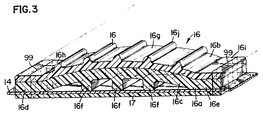
- the stay is generally designated at 16 and is shown on the back support in Figs. 1 and 2 and in more detail in Fig. 3.
- the stay, generally designated as 16, includes a base member 16a and a gripping member 16b operatively connected to the base member 16a.
- the base member 16a has a generally curved cross-section 16c for added rigidity.
- the base member has two flanges 16d and 16e operatively connected to the curved section 16c at each end.
- the curved section provides for increased rigidity without using as much material as would be required if the base member was flat.
- a plurality of ribs 16f are operatively connected to the base member 16a again for increased rigidity.
- the gripping member 16b has a profile which matches the base member 16a.
- the stays are attached to the fabric 14 of the back support by any suitable means such as stitching.
- This method of attachment is shown in Fig. 3 wherein the stay 16 is stitched by means of stitches 99 to fabric 14.
- a strip of fabric material 17 is on the opposite side of the fabric 14 than the stay and the stitching 99 goes through the stay 16, fabric 14 and strip 17.
- the strip 17 may be any suitable fabric such as a leather-like material or webbing.
- the stay may be connected without the use of the strip material 17. It is also understood that other suitable means besides sewing could be utilized, such as heat transfer, adhesives, rivets, staples, tape or other fastening techniques.
- the stay 16 is a single component and is manufactured by dual extrusion process. It is necessary that this stay provides a necessary rigidity to provide proper support while still having a high coefficient of drag to prevent "riding up". To obtain a high coefficient of drag, the material needs to be flexible which is the opposite of the requirement for a rigid support. The present invention combines both of these properties into one integral unit that can be easily sewn in place.
- the base member 16a (which includes the flanges 16d and 16e and the ribs 16f) is constructed of a material which has more rigidity, such as a rigid thermoplastic like polypropylene.
- the base member has a hardness of from 65 to 85 Rockwell hardness and preferably 70R-80R and more preferably 75R.
- the base 16a has been designed with a curved section 16c and a plurality of ribs 16f which design provides more rigidity while requiring less material.
- the gripping member 16b (which includes the flanges 16h and 16i and the ribs 16j) is constructed from a softer material such as a blend of polypropylene and rubber, such as that sold under the brand name Santoprene.
- a grade 7823 polypropylene is utilized and a 101-64 Santoprene is utilized. This is a Santoprene with a 64 durometer on the Shore A scale.
- a hardness of from 55 to 73, Shore A scale is acceptable for providing a gripping member preferably from 60-70 Shore A.
- a plurality of projection 16j are on the top portion of the gripping member 16b, thereby providing a gripping enhancement to the gripping member 16b.
- the two materials are extruded separately and they pass through the dual extrusion die which configures the material into the desired cross-section. Being composed of the same base material, the two materials bond together and are permanently bonded. The process is void of any adhesives or solvents and the two materials cannot be separated without destroying the integrity of the materials. While this is the preferred embodiment, it is also understood that the stay may be made by alternate methods. These methods would include dual injected molding or extruding the two members separately and bonding them together with a suitable adhesive, tape or sewing them together in the back support. Still further, other rigid plastic materials such as ABS, polyethylene, nylon, polystyrene and the like may be used as well as other rubber-like materials may be utilized for the gripping member 16b.
- Rubber-like materials could include TPR, vyram, silicone, rubber, crayton, thermoplastic elastomers, rubber like plastics and the like. It is of course also understood that other cross-sections could be utilized as well as different gripping enhancement means. Instead of the ribs 16j, there could be textured surface by way of squiggles, dots, or secondary operations such as calendaring could be used to increase the coefficient of drag.
- the stay 16 has an overall width of approximately 1 inch and a length of approximately 8 inches, while it is understood that other suitable dimensions may be utilized.
- the stay is generally designated at 116 and includes a base member 116a and a gripping 116b operatively connected to the base member 116a.
- the base member 116a has a generally curved cross-section 116c for added rigidity.
- the base member has two flanges 116d and 116e operatively connected to the curved section 116 at each end.
- the curved section provides for increased rigidity without using as much material as would be required if the base member was flat.
- a rib 116f is operatively connected to the underneath side of base member 116a again for increased rigidity.
- the gripping member 116d has a profile which matches the base member 116a.
- a curved center section 116g there is a curved center section 116g and operatively connected at its two ends are two flanges, 116h and 116i.
- a planar area 130 and 140 which is an extension of the base 116a and formed from the same material as the base 116a.
- the flanges 116h and 116i extend slightly beyond the flanges 116d and 116e, thereby the base member 116a is encompassed on three of its sides by the gripping member 116b.
- a plurality of elongate ribs 116j are operatively connected to the outer surface of the curved section 116g.
- the ribs 116j provide for gripping enhancement. As shown in Fig.
- the stays are attached to the fabric 14 of the back support by suitable means such as stitching.
- This method of attachment is shown in Fig. 5, wherein the stay 116 is stitched by means of stitches 199 to fabric 14.
- the stay 116 has two attachment areas 120 and 121, which are formed at the ends of the stays.
- the gripping member 116b extends beyond the ends of the base 116a to form the attachment areas 120 and 121.
- the attachment areas 120 and 121 provide an area where the stitching 199 can be sewn through the stay 116 on to the fabric 14, without the necessity of going through the harder base 116a.
- attachment areas 120 and 121 provides for the end of the stay 116 to be softer and thereby more comfortable to the user as the ends of the stay do not dig into the wearer. Still further, the flanges 116h and 116i extend around the base flanges 116d and 116e, thereby again providing a softer feel to the user.
- the stay 116 is a single component and is manufactured by double shot injection molding (dual injected molding) process.
- the materials for the base 116a which now also includes areas 130 and 140, are the same as that previously set forth with respect to the stay 16.
- the materials for the gripping member 116b which now also includes the attachment areas 120 and 121, is the same as that for the gripping member 116b and their qualities and properties will not be again stated, but are those as set forth with respect to the stay 16.
Landscapes
- Health & Medical Sciences (AREA)
- Nursing (AREA)
- Orthopedic Medicine & Surgery (AREA)
- Engineering & Computer Science (AREA)
- Biomedical Technology (AREA)
- Heart & Thoracic Surgery (AREA)
- Vascular Medicine (AREA)
- Life Sciences & Earth Sciences (AREA)
- Animal Behavior & Ethology (AREA)
- General Health & Medical Sciences (AREA)
- Public Health (AREA)
- Veterinary Medicine (AREA)
- Details Of Garments (AREA)
- Professional, Industrial, Or Sporting Protective Garments (AREA)
- Orthopedics, Nursing, And Contraception (AREA)
Applications Claiming Priority (4)
| Application Number | Priority Date | Filing Date | Title |
|---|---|---|---|
| US14106 | 1993-02-05 | ||
| US08/014,106 US5388273A (en) | 1993-02-05 | 1993-02-05 | Support stay |
| US08/105,032 US5426791A (en) | 1993-02-05 | 1993-08-11 | Support stay |
| US105032 | 1993-08-11 |
Publications (1)
| Publication Number | Publication Date |
|---|---|
| EP0619103A1 true EP0619103A1 (de) | 1994-10-12 |
Family
ID=26685666
Family Applications (1)
| Application Number | Title | Priority Date | Filing Date |
|---|---|---|---|
| EP93202725A Withdrawn EP0619103A1 (de) | 1993-02-05 | 1993-09-20 | Versteifungselement |
Country Status (6)
| Country | Link |
|---|---|
| US (1) | US5426791A (de) |
| EP (1) | EP0619103A1 (de) |
| JP (1) | JPH06237951A (de) |
| AU (1) | AU4748493A (de) |
| CA (1) | CA2106445C (de) |
| MX (1) | MX9306471A (de) |
Cited By (6)
| Publication number | Priority date | Publication date | Assignee | Title |
|---|---|---|---|---|
| FR2772596A1 (fr) * | 1997-12-19 | 1999-06-25 | Thuasne Sa | Article medical de contention |
| EP0970668A1 (de) * | 1998-07-10 | 2000-01-12 | Becton Dickinson and Company | Mehrschichtige orthopädische Stütze |
| EP1050287A1 (de) | 1999-05-07 | 2000-11-08 | Thuasne | Medizinischer Kompressionsartikel |
| DE10103545A1 (de) * | 2001-01-26 | 2002-08-01 | Beiersdorf Ag | Pelotte insbesondere für Rückenstützbandagen |
| FR2897530A1 (fr) * | 2006-02-22 | 2007-08-24 | Jean Paul Parizot | Dispositif pour le maintien des vertebres lombaires et/ou des muscles sacro spinaux |
| WO2017044995A1 (en) * | 2015-09-08 | 2017-03-16 | Earle John Loxton | Protective buffer strap |
Families Citing this family (21)
| Publication number | Priority date | Publication date | Assignee | Title |
|---|---|---|---|---|
| US5782782A (en) * | 1996-05-24 | 1998-07-21 | Boston Brace International Inc. | Support belt with corrective angle of lordosis |
| JP3793778B2 (ja) * | 1997-10-03 | 2006-07-05 | ダイヤ工業株式会社 | 腰椎帯 |
| US6257951B1 (en) | 1998-01-22 | 2001-07-10 | Demarco Jill R. | Reusable strapless backless bra |
| US6199811B1 (en) * | 1998-12-15 | 2001-03-13 | Larry S. Fargo | Deformable safety hook |
| US8113908B1 (en) | 2000-07-20 | 2012-02-14 | Dba Lux 1 Sarl | Stiffened brassiere |
| US7690965B2 (en) * | 2001-02-06 | 2010-04-06 | Hbi Branded Apparel Enterprises, Llc | Methods of making cotton blend glue brassieres |
| US6837771B2 (en) | 2001-02-06 | 2005-01-04 | Playtex Apparel, Inc. | Undergarments made from multi-layered fabric laminate material |
| KR100417332B1 (ko) * | 2001-02-20 | 2004-02-05 | 김대관 | 척추 보호대 |
| US6832785B1 (en) * | 2003-07-21 | 2004-12-21 | Itt Manufacturing Enterprises, Inc. | Spin welded fluid coupling |
| CA2451714A1 (en) * | 2003-12-22 | 2005-06-22 | Karine Ishkhanova | Waistband with sculptured layer for back support while in lying or sitting position |
| US8328742B2 (en) | 2009-09-25 | 2012-12-11 | Medical Technology Inc. | Adjustable orthopedic back brace |
| US8990965B2 (en) * | 2010-03-01 | 2015-03-31 | Global Trademarks, Llc | Garment with slip-resistant liner |
| US20110295317A1 (en) * | 2010-05-25 | 2011-12-01 | Busch Iii Richard E | Restraint system for a spinal decompression table |
| US8808213B2 (en) | 2010-05-28 | 2014-08-19 | Hendricks Orthotic Prosthetic Enterprises, Inc. | Mechanically advantaged spinal system and method |
| US10350104B2 (en) | 2015-07-15 | 2019-07-16 | Scott Specialties, Inc. | Orthopedic brace and method of making the same |
| USD808027S1 (en) | 2016-07-13 | 2018-01-16 | Scott Specialties, Inc. | Moldable wrist brace |
| US10709188B2 (en) * | 2016-07-19 | 2020-07-14 | Tedder Industries, LLC | Metal reinforced belt |
| ES1184534Y (es) * | 2017-04-21 | 2017-09-08 | Rm Urgecamino S L | Dispositivo corrector postural |
| US11540935B2 (en) * | 2017-06-07 | 2023-01-03 | Ortho Systems | Welded back brace |
| US11006686B2 (en) | 2018-05-31 | 2021-05-18 | Nike, Inc. | Grip-enhancing film for cuff edges |
| USD909590S1 (en) | 2019-04-23 | 2021-02-02 | Scott Specialties, Inc. | Thumb brace |
Citations (4)
| Publication number | Priority date | Publication date | Assignee | Title |
|---|---|---|---|---|
| US3926186A (en) * | 1973-03-27 | 1975-12-16 | Robert P Nirschl | Muscular support |
| DE8213379U1 (de) * | 1982-10-21 | Bauerfeind Gmbh, 4152 Kempen | Kreuzstützbandage | |
| DE3531573C1 (en) * | 1985-09-04 | 1987-03-26 | Juergen Chitralla | Sports belt, especially for weightlifting |
| US5040524A (en) * | 1990-04-30 | 1991-08-20 | Ergodyne Corporation | Back support |
Family Cites Families (15)
| Publication number | Priority date | Publication date | Assignee | Title |
|---|---|---|---|---|
| US603932A (en) * | 1898-05-10 | Smith tucker | ||
| US627807A (en) * | 1899-03-28 | 1899-06-27 | William H Harrington | Truss. |
| US1606214A (en) * | 1926-01-26 | 1926-11-09 | Victor F Ferron | Abdominal truss |
| US1918590A (en) * | 1928-11-23 | 1933-07-18 | Franz S Burton | Truss |
| US1925615A (en) * | 1929-03-08 | 1933-09-05 | Stuart Frank Joseph | Pad supporting and locating appliance |
| US3020557A (en) * | 1960-05-02 | 1962-02-13 | Sobel Morton | Garment bone |
| AR205768A1 (es) * | 1975-01-07 | 1976-05-31 | Waldmann J | Faja antiptosis |
| US3970079A (en) * | 1975-03-21 | 1976-07-20 | Medical Specialties, Inc. | Body support binder and method of fabricating same |
| US4441211A (en) * | 1983-03-25 | 1984-04-10 | Houston Protective Equipment, Inc. | Protective batting jacket |
| US4884562A (en) * | 1985-06-03 | 1989-12-05 | Stone Mario M | Suspension brace assembly |
| US5072725A (en) * | 1990-04-27 | 1991-12-17 | Miller Marion E | Soft body brace |
| US5274846A (en) * | 1990-06-12 | 1994-01-04 | Hpi Health Protection, Inc. | Cushion having multilayer closed cell structure |
| US5111906A (en) * | 1991-02-07 | 1992-05-12 | Auguste Abadia | Retractable ladder apparatus |
| US5148549A (en) * | 1991-04-23 | 1992-09-22 | Ergodyne Corporation | Back support with side openings and attached apron |
| US5250345A (en) * | 1992-02-21 | 1993-10-05 | Chu Chih Ming | Anti-slip device for a belt |
-
1993
- 1993-08-11 US US08/105,032 patent/US5426791A/en not_active Expired - Lifetime
- 1993-09-17 CA CA002106445A patent/CA2106445C/en not_active Expired - Lifetime
- 1993-09-20 EP EP93202725A patent/EP0619103A1/de not_active Withdrawn
- 1993-09-20 AU AU47484/93A patent/AU4748493A/en not_active Abandoned
- 1993-10-18 MX MX9306471A patent/MX9306471A/es unknown
- 1993-11-29 JP JP5323280A patent/JPH06237951A/ja not_active Withdrawn
Patent Citations (4)
| Publication number | Priority date | Publication date | Assignee | Title |
|---|---|---|---|---|
| DE8213379U1 (de) * | 1982-10-21 | Bauerfeind Gmbh, 4152 Kempen | Kreuzstützbandage | |
| US3926186A (en) * | 1973-03-27 | 1975-12-16 | Robert P Nirschl | Muscular support |
| DE3531573C1 (en) * | 1985-09-04 | 1987-03-26 | Juergen Chitralla | Sports belt, especially for weightlifting |
| US5040524A (en) * | 1990-04-30 | 1991-08-20 | Ergodyne Corporation | Back support |
Cited By (9)
| Publication number | Priority date | Publication date | Assignee | Title |
|---|---|---|---|---|
| FR2772596A1 (fr) * | 1997-12-19 | 1999-06-25 | Thuasne Sa | Article medical de contention |
| EP0970668A1 (de) * | 1998-07-10 | 2000-01-12 | Becton Dickinson and Company | Mehrschichtige orthopädische Stütze |
| EP1050287A1 (de) | 1999-05-07 | 2000-11-08 | Thuasne | Medizinischer Kompressionsartikel |
| DE10103545A1 (de) * | 2001-01-26 | 2002-08-01 | Beiersdorf Ag | Pelotte insbesondere für Rückenstützbandagen |
| WO2002058602A1 (de) | 2001-01-26 | 2002-08-01 | Beiersdorf Ag | Pelotte insbesondere für rückenstützbandagen |
| FR2897530A1 (fr) * | 2006-02-22 | 2007-08-24 | Jean Paul Parizot | Dispositif pour le maintien des vertebres lombaires et/ou des muscles sacro spinaux |
| WO2007096370A1 (fr) * | 2006-02-22 | 2007-08-30 | Jean-Paul Parizot | Dispositif pour le maintien des vertèbres lombaires et/ou des muscles sacro spinaux |
| WO2017044995A1 (en) * | 2015-09-08 | 2017-03-16 | Earle John Loxton | Protective buffer strap |
| US10526119B2 (en) | 2015-09-08 | 2020-01-07 | Earle John Loxton | Protective buffer strap |
Also Published As
| Publication number | Publication date |
|---|---|
| JPH06237951A (ja) | 1994-08-30 |
| AU4748493A (en) | 1994-08-11 |
| CA2106445A1 (en) | 1994-08-06 |
| US5426791A (en) | 1995-06-27 |
| MX9306471A (es) | 1994-08-31 |
| CA2106445C (en) | 1997-11-25 |
Similar Documents
| Publication | Publication Date | Title |
|---|---|---|
| US5426791A (en) | Support stay | |
| US5388273A (en) | Support stay | |
| US5727720A (en) | Modular hip-supported pack with bilateral articulation | |
| US5361955A (en) | Modular backpack | |
| US4289137A (en) | Sports brassiere | |
| EP0636325B1 (de) | Bekleidung mit Lendenstütze | |
| US5257419A (en) | Abdominal support belt | |
| US6279168B1 (en) | Wrapping device and methods | |
| US5452477A (en) | Item of swimming wear | |
| US4217905A (en) | Athletic brassiere | |
| EP2789316A2 (de) | Träger | |
| CA2607558C (en) | Corset | |
| US20030135913A1 (en) | Extendible belt | |
| US3812862A (en) | Waist-supporting garment | |
| US6322462B1 (en) | Elbow brace for teaching baseball throwing | |
| US5762619A (en) | Fashion belt with built-in lumbar support | |
| US20230240401A1 (en) | Pair of trousers comprising a waistband system | |
| US4108149A (en) | Maternity brace | |
| AU773414B2 (en) | Elbow brace for teaching baseball throwing | |
| US20160143765A1 (en) | Compression Garment for Postpartum Women | |
| JP3925948B2 (ja) | 腰痛緩和ベルト | |
| CN2889215Y (zh) | 托腹带 | |
| JP7376074B2 (ja) | サポーター付きズボン | |
| AU2018229438B2 (en) | Protective vest for an animal | |
| EP3875064A1 (de) | Rückenorthese |
Legal Events
| Date | Code | Title | Description |
|---|---|---|---|
| PUAI | Public reference made under article 153(3) epc to a published international application that has entered the european phase |
Free format text: ORIGINAL CODE: 0009012 |
|
| AK | Designated contracting states |
Kind code of ref document: A1 Designated state(s): AT BE CH DE DK ES FR GB GR IE IT LI LU MC NL PT SE |
|
| 17P | Request for examination filed |
Effective date: 19950120 |
|
| 17Q | First examination report despatched |
Effective date: 19960923 |
|
| 18D | Application deemed to be withdrawn |
Effective date: 19970204 |