EP0619131B1 - Séparateur de liquide léger avec fermeture automatique - Google Patents
Séparateur de liquide léger avec fermeture automatique Download PDFInfo
- Publication number
- EP0619131B1 EP0619131B1 EP94105282A EP94105282A EP0619131B1 EP 0619131 B1 EP0619131 B1 EP 0619131B1 EP 94105282 A EP94105282 A EP 94105282A EP 94105282 A EP94105282 A EP 94105282A EP 0619131 B1 EP0619131 B1 EP 0619131B1
- Authority
- EP
- European Patent Office
- Prior art keywords
- light liquid
- liquid separator
- separator according
- linkage
- light
- Prior art date
- Legal status (The legal status is an assumption and is not a legal conclusion. Google has not performed a legal analysis and makes no representation as to the accuracy of the status listed.)
- Expired - Lifetime
Links
- 239000007788 liquid Substances 0.000 title claims abstract description 126
- 230000007246 mechanism Effects 0.000 claims abstract description 18
- 230000001419 dependent effect Effects 0.000 claims abstract 2
- 239000000203 mixture Substances 0.000 claims description 14
- 238000007654 immersion Methods 0.000 claims description 4
- 239000011796 hollow space material Substances 0.000 claims 1
- 238000000926 separation method Methods 0.000 abstract description 22
- 230000005484 gravity Effects 0.000 abstract 1
- 239000007787 solid Substances 0.000 abstract 1
- 230000001960 triggered effect Effects 0.000 abstract 1
- XLYOFNOQVPJJNP-UHFFFAOYSA-N water Substances O XLYOFNOQVPJJNP-UHFFFAOYSA-N 0.000 description 3
- 238000004581 coalescence Methods 0.000 description 2
- 238000005381 potential energy Methods 0.000 description 2
- 229910000831 Steel Inorganic materials 0.000 description 1
- 238000009825 accumulation Methods 0.000 description 1
- 230000004888 barrier function Effects 0.000 description 1
- 230000008901 benefit Effects 0.000 description 1
- 238000010276 construction Methods 0.000 description 1
- 238000011161 development Methods 0.000 description 1
- 230000018109 developmental process Effects 0.000 description 1
- 230000009467 reduction Effects 0.000 description 1
- 239000011150 reinforced concrete Substances 0.000 description 1
- 230000000284 resting effect Effects 0.000 description 1
- 230000000630 rising effect Effects 0.000 description 1
- 230000035945 sensitivity Effects 0.000 description 1
- 239000010959 steel Substances 0.000 description 1
Images




Classifications
-
- E—FIXED CONSTRUCTIONS
- E03—WATER SUPPLY; SEWERAGE
- E03F—SEWERS; CESSPOOLS
- E03F5/00—Sewerage structures
- E03F5/14—Devices for separating liquid or solid substances from sewage, e.g. sand or sludge traps, rakes or grates
- E03F5/16—Devices for separating oil, water or grease from sewage in drains leading to the main sewer
-
- B—PERFORMING OPERATIONS; TRANSPORTING
- B01—PHYSICAL OR CHEMICAL PROCESSES OR APPARATUS IN GENERAL
- B01D—SEPARATION
- B01D17/00—Separation of liquids, not provided for elsewhere, e.g. by thermal diffusion
- B01D17/02—Separation of non-miscible liquids
- B01D17/0208—Separation of non-miscible liquids by sedimentation
-
- B—PERFORMING OPERATIONS; TRANSPORTING
- B01—PHYSICAL OR CHEMICAL PROCESSES OR APPARATUS IN GENERAL
- B01D—SEPARATION
- B01D17/00—Separation of liquids, not provided for elsewhere, e.g. by thermal diffusion
- B01D17/02—Separation of non-miscible liquids
- B01D17/0208—Separation of non-miscible liquids by sedimentation
- B01D17/0214—Separation of non-miscible liquids by sedimentation with removal of one of the phases
Definitions
- Light liquid separators are used wherever light liquids, especially oil, petrol or the like, must not be discharged into the public sewer system. They have a separation chamber in which the light liquid is separated from the heavy liquid, usually water, so that the cleaned heavy liquid can be discharged into the sewer network or an open body of water via the outlet of the separator. To promote the separation, coalescence elements can be provided in the separation chamber, in which the light liquid dispersed in the heavy liquid is given the opportunity to coalesce.
- Light liquid separators of this type usually do not have their own drain for the light liquid; the light liquid separated from the heavy liquid rather collects in the separation chamber above the heavy liquid and is periodically or if necessary sucked off or pumped out from there.
- the layer thickness of which in the separating chamber increases with increasing inflow, cannot get into the outlet for the heavy liquid leading to the sewer network, such separators are provided with an automatic seal. This closure either closes the inlet or the outlet when the level of the heavy liquid in the separation chamber falls below a certain level or the thickness of the light liquid layer exceeds a certain height.
- the closure closes the drain of the separator (EP-B 0 276 861).
- the end consists of a horizontally arranged flap which is connected to a float by a vertical rod.
- the end is located in front of the drain pipe, which is designed as a dip tube and has a pipe socket on the bottom of the container with an upper horizontal drain opening for the heavy liquid, which can be closed by the closure flap like a cover.
- the float floats on the heavy liquid. If the level of heavy liquid in the separation chamber drops due to the increasing accumulation of light liquid, the float and the flap connected to it also sink until it closes the outlet for the heavy liquid at a certain - adjustable - level of the heavy liquid level.
- the inlet is closed by a valve cover which can be swivel-controlled either pivoted about a horizontal pivot axis in front of the inlet opening or guided in front of the inlet opening by a parallelogram-like linkage (AT 393 670 B).
- a parallelogram-like linkage AT 393 670 B
- the invention has for its object to provide a light liquid separator of the type mentioned with an easily and reliably functioning automatic closure and at the same time to use the surface or length of the separator as completely as possible for the separation process.
- the basic idea of the invention is to provide, as a conclusion, a rotary flap which is arranged within a vertical dip tube which is present anyway and can thus be provided either in the inlet or in the outlet area.
- the base area of the separator can be fully used for the separation process and both the inlet and the outlet area can be optimally designed.
- the closure according to the invention can be arranged not only in the outlet area but also in the inlet area of a container.
- the inlet When arranged in the inlet area, when the layer of light liquid floating on the heavy liquid exceeds a certain height, the inlet is closed, so that no further liquid can get into the separation chamber. Then there is backflow of the mixture in the feed area; however, this can be accepted, since the inlet area is contaminated with light liquid anyway and sealed accordingly.
- the light liquid separator consists of a container 1 designed as a prefabricated reinforced concrete component with a cylindrical outer wall 2 and a sole 3 which form a separation chamber 4.
- the container 1 has an inlet 5 for the light / heavy liquid mixture on one side and an outlet 6 for the heavy liquid freed from the light liquid on the opposite side.
- the light / heavy liquid mixture flows through an inlet pipe 7, which is located within the container vertical dip tube 8 continues in the separation chamber 4.
- the separation can be intensified and accelerated by installing a coalescence barrier 9, indicated by dashed lines.
- the liquid level of the light liquid is indicated at 10, that of the heavy liquid at 11.
- the heavy liquid collected at the bottom of the separating chamber 4 and freed from the light liquid rises on the side opposite the inlet 5 behind a baffle 12 and is drawn off via an outlet pipe 13.
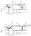
- the automatic closure is provided in the inlet area, specifically as a rotary flap 14 within the immersion tube 8; it can be explained in more detail with reference to FIG. 3, which shows a first embodiment on a larger scale as a detail from FIG. 1.
- FIG. 3 shows the automatic closure in the operating position, ie with the rotary flap 14 open.
- the rotary flap 14 is rotatably mounted in the dip tube 8 about an axis of rotation 15 in a steel ring 16.
- the rotary flap 14 is connected in a rotationally fixed manner to one end of a lower rod 18 of a parallelogram-like rod 17, which also has a vertical rod 19 and an upper rod 20.
- the rods 18, 19 and 20 are each hinged together at 21.
- the upper rod 20 is articulated at its other end at 22 in a bearing 23 which is fastened to the dip tube 8 on an inclined cover plate 24.
- the rotary flap 14 can be opened or closed by moving the linkage 17 up or down in the direction of the double arrow 25, the rods 18 and 19 each being pivoted through an angle of 90 degrees.
- similar rods 17 ′ and 17 ′′ can be symmetrical about the sides of the dip tube 8 be arranged.
- a control body 26 or control bodies 26 ′, 26 ′′ are fastened to the vertical rod 19 or the rods 19 ′, 19 ′′, which in the illustrated embodiment each consist of a cylindrical tube open at the top.
- the control body 26 is arranged on the linkage 17 so that its upper edge 27 is in the operating state below the liquid level 10; it therefore fills itself with liquid as the liquid level rises, with a mixture of light and heavy liquid.
- FIG. 3 further shows, there is a check valve 29 on the bottom 28 of the control body 26, which only allows the control body 26 to be emptied. If the liquid level in the separating chamber 4 rises slowly during start-up, no liquid can initially penetrate into the control body 26; in this phase, the control body 26 acts like a float and lifts the linkage 17. The linkage 17 can only be raised by the control body 26 to the position shown, in which the rotary flap 14 is open. In this state, the upper edge 27 of the control body 26 is below the liquid level 10, so that it fills with liquid.
- a trigger mechanism 30 is located above the dip tube 8 on the cover plate 24.
- this trigger mechanism 30 a permanent magnet 31 which is arranged on a threaded spindle 32 parallel to the upper rod 20 to move longitudinally; the threaded spindle 32 is held on a bearing plate 33, which is also attached to the cover plate 24. Is on the bearing plate 33 further articulated a locking lever 34 which carries a hook 35 at the front end and a counterweight 36 at the rear end.
- Both the trigger mechanism 30, i.e. the permanent magnet 31, and the locking lever 34 with the hook 35 act against a lever 37, which is arranged parallel to the upper rod 20 of the linkage 17 above the dip tube 8 and is rotatably connected to the shaft 38 which forms the joint 22 for the linkage 17 and which carries the upper rod 20 at the end or the upper rods 20 ', 20' 'at the ends.
- the rotary flap 14 When filling the container 1 (Fig. 6) for commissioning or recommissioning, the rotary flap 14 must be kept in the open position to allow the inlet. If the magnetic force of the permanent magnet 31 is not sufficient for this purpose, mechanical locking by means of the locking lever 34 can also take place.
- the magnetic force of the permanent magnet 31, which can be precisely defined via a longitudinal adjustment of the same for changing the lever arm of the attacking force, is set so that the differential weight of the linkage 17 for buoyancy in the heavy liquid as well as a certain release weight are just still be held. If the container 1 is filled, the lever 34 must of course be released from the locked position. This is achieved by means of the counterweight 36, which guides the lever 34 into its rest position, whereby the system is unlocked (FIG. 3).
- the light liquid accumulating in the separation chamber 4 above the heavy liquid during operation displaces the heavy liquid in the upper region. If the light liquid layer reaches the upper edge 27 of the control body 26 with its lower edge, it cannot penetrate into the cavity because it is filled with heavy liquid. With further separation of light liquid and a corresponding drop in the heavy liquid level 11, the lift acting on the control body 26 is reduced; an additional force begins to act on the permanent magnet 31, which finally leads to a loosening of the hold-up caused by it.
- the rotary flap 14 is now closed by the potential energy of the falling rod 17 (FIG. 5).
- the lever 37 experiences a stop against a buffer 39 during the downward movement of the linkage 17.
- FIGS. 7 to 10 show another embodiment of the automatic closure according to the invention, which differs from that according to FIGS. 3 to 6 essentially by the design of the release mechanism 40 for the rotary flap 14. Accordingly, corresponding parts of the automatic closure are also designated with the same reference numerals; this applies in particular to the rotary flap 14 and the parallelogram-like linkage 17 and the control body 26.
- the different design of the trigger mechanism 40 is first explained below with reference to FIGS. 7 and 8, with FIG. 7 a side view and FIG. 8 a front view of the inlet area show the automatic closure.
- the lever 37 which keeps the rotary flap 14 open is designed as a roller pawl 41, which is equipped with a roller 42 and, parallel to the upper rod 20 of the linkage 17, with the shaft 43 in a rotationally fixed manner and via this also with movement the linkage 17 is connected.
- the roller pawl 41 cooperates with a roll bar 44, which consists of an angular part 45 and a curved part 46; the roll bar 44 is pivotally mounted about a horizontal axis 47.
- the roll bar 41 can be pressed against the roller 42 of the roller latch by means of a tension spring 48 which interacts with the angular part 47. In this way, the triggering force for the linkage 17 actuating the rotary flap 14 can be adjusted as a function of the thickness of the light liquid layer.
- the roller pawl 41 In the operating position shown in FIG. 7, the roller pawl 41 is held in operative connection with the spring-loaded unrolling bracket 44 by the tension spring 48, which is prestressed according to the respective density of the light liquid, until the maximum thickness of the light liquid layer is reached. Due to the loss of buoyancy with heavy liquid filled control body 26, which can be filled here via openings 57, the roller pawl 41 is released from the spring-loaded unrolling bracket 44 at a certain thickness of the light liquid layer. During the downward movement of the linkage 17, which can be supported by a falling weight 49, the roller 42 of the roller pawl 41 rolls on the curved part 46 of the roll bar 44. As a result, the rotary flap 14 is closed. 9 shows the closed position.
- the linkage 17 is guided upwards via a pulling device 50 until the roller 42 snaps back into its basic position on the roller pawl 41. Since the buoyancy is still missing in this state, restraint is required, which is brought about by a holding pawl 51.
- the holding pawl 41 like the roll-off bracket 44, is mounted on a bearing bracket 52; it cooperates with a bolt 53 on the roller pawl 41.
- the holding pawl 51 is connected to a float ball 55 via a float rod 54; the float rod 54 is guided in a float guide 56.
- the float ball 55 receives a buoyancy above the fill level of the control body 26, which decouples the holding pawl 51 from the bolt 53 without friction up to the resting water level. This is achieved in that the buoyancy of the float ball 55 only begins when the control body 26 filled with heavy liquid no longer experiences a loss of buoyancy and is already held by the trigger mechanism 40.
- the particular advantage of this embodiment is that the system is extremely easy to move.
- the friction of roller pawl 41, roll bar 44, linkage 17 and rotary flap 14 is largely minimized by the construction; this significantly increases the sensitivity of the system.
Landscapes
- Physics & Mathematics (AREA)
- Chemical Kinetics & Catalysis (AREA)
- Chemical & Material Sciences (AREA)
- Thermal Sciences (AREA)
- Public Health (AREA)
- Water Supply & Treatment (AREA)
- Health & Medical Sciences (AREA)
- Hydrology & Water Resources (AREA)
- Engineering & Computer Science (AREA)
- Life Sciences & Earth Sciences (AREA)
- Removal Of Floating Material (AREA)
- Float Valves (AREA)
- Investigating Or Analysing Biological Materials (AREA)
- Centrifugal Separators (AREA)
- Closures For Containers (AREA)
- Loading And Unloading Of Fuel Tanks Or Ships (AREA)
- Infusion, Injection, And Reservoir Apparatuses (AREA)
- External Artificial Organs (AREA)
- Separation Using Semi-Permeable Membranes (AREA)
Claims (17)
- Séparateur de liquides légers possédant une admission (5) pour un mélange de liquides légers/lourds, une chambre de séparation (4) destinée à séparer le mélange et une évacuation (6) pour le liquide lourd, l'admission et/ou l'évacuation présentant l'une et l'autre un tube plongeur (8, 12), et possédant également une fermeture automatique pouvant être commandée par la différence entre les poids volumiques du liquide lourd et du liquide léger et réalisée sous la forme d'un clapet rotatif (14), caractérisé en ce que le clapet rotatif (14) est agencé dans l'admission ou l'évacuation à l'intérieur du tube plongeur (8) et peut pivoter autour d'un axe (15) qui croise l'axe longitudinal de celui-ci à angle droit, en ce que le clapet rotatif (14) est relié en rotation de manière solidaire à une extrémité d'une tige inférieure (18) d'une tringlerie de type parallélogramme (17) qui comporte, outre une tige verticale (19) reliée de manière articulée à l'autre extrémité de la tige (18), une tige supérieure (20) dont une extrémité est reliée de manière articulée à la tige verticale (19) et dont l'autre extrémité est articulée sur ladite tige au-dessus du niveau du liquide léger (10) dans le prolongement de l'axe longitudinal du tube plongeur (8), et en ce qu'il est prévu un mécanisme de déclenchement (30, 40) concourant avec la tringlerie (17), maintenant celle-ci en position relevée et le clapet rotatif (14) en position ouverte, qui peut être déclenché par une force de commande dépendant de la différence entre les poids volumiques du liquide lourd et du liquide léger, de telle sorte que la tringlerie (17) se déplace vers le bas et que le clapet rotatif (14) se ferme.
- Séparateur de liquides légers selon la revendication 1, caractérisé en ce que, pour augmenter la force de commande, au moins un élément de commande (26) creux pouvant être rempli avec un liquide lourd est agencé sur la tringlerie (17).
- Séparateur de liquides légers selon la revendication 2, caractérisé en ce que l'élément de commande (26) est fixé sur la tige verticale (19).
- Séparateur de liquides légers selon la revendication 2 ou la revendication 3, caractérisé en ce que l'élément de commande (26) se compose d'un tube cylindrique fermé au moins à son extrémité inférieure, ayant son axe longitudinal parallèle à la tige verticale (19) et présentant dans sa partie supérieure une ouverture (27, 57) d'admission du liquide lourd.
- Séparateur de liquides légers selon l'une quelconque des revendications 2 à 4, caractérisé en ce que l'élément de commande (26) est muni à son extrémité inférieure d'un clapet antiretour (29) permettant de vider la cavité.
- Séparateur de liquides légers selon l'une quelconque des revendications 1 à 5, caractérisé en ce que le mécanisme de déclenchement (30, 40) est agencé au-dessus du niveau du liquide léger (10).
- Séparateur de liquides légers selon l'une quelconque des revendications 1 à 6, caractérisé en ce que le mécanisme de déclenchement (30, 40) coopère avec un levier (37, 41) relié à la tringlerie (17) de manière positive.
- Séparateur de liquides légers selon la revendication 7, caractérisé en ce que le levier (37, 41) est agencé parallèlement à la tige supérieure (20) de la tringlerie (17).
- Séparateur de liquides légers selon l'une quelconque des revendications 1 à 8, caractérisé en ce qu'un aimant permanent (31) est prévu comme mécanisme de déclenchement (30).
- Séparateur de liquides légers selon la revendication 9, caractérisé en ce que l'aimant permanent (31) est réglable parallèlement à la direction d'avance du levier (37).
- Séparateur de liquides légers selon la revendication 10, caractérisé en ce que l'aimant permanent (31) repose sur une tige filetée (32) mobile autour d'un axe.
- Séparateur de liquides légers selon l'une quelconque des revendications 1 à 8, caractérisé en ce que le mécanisme de déclenchement (40) est un étrier de roulement (44) concourant avec un levier réalisé sous la forme d'un cliquet à galet (41), ledit cliquet à galet (41) présentant un galet (42) pouvant rouler sur le périmètre de la partie curviligne (46) de l'étrier de roulement (44).
- Séparateur de liquides légers selon la revendication 12, caractérisé en ce que l'étrier de roulement (44) peut être pressé contre le galet (42) au moyen d'un élément à ressort.
- Séparateur de liquides légers selon la revendication 13, caractérisé en ce qu'un ressort de traction (48) est prévu comme élément à ressort.
- Séparateur de liquides légers selon l'une quelconque des revendications 12 à 14, caractérisé en ce que, pour augmenter la force de fermeture, un contrepoids (49) est agencé sur la tringlerie.
- Séparateur de liquides légers selon l'une quelconque des revendications 1 à 15, caractérisé en ce que la tringlerie (17) comporte un mécanisme de verrouillage (34, 35 ou 51, 53) coopérant avec le levier (37, 41).
- Séparateur de liquides légers selon la revendication 16, caractérisé en ce que le mécanisme de verrouillage présente un loquet de maintien (51) coopérant avec le levier (41).
Applications Claiming Priority (2)
| Application Number | Priority Date | Filing Date | Title |
|---|---|---|---|
| DE4311719A DE4311719A1 (de) | 1993-04-08 | 1993-04-08 | Leichtflüssigkeitsabscheider mit einem selbsttätigen Abschluß |
| DE4311719 | 1993-04-08 |
Publications (2)
| Publication Number | Publication Date |
|---|---|
| EP0619131A1 EP0619131A1 (fr) | 1994-10-12 |
| EP0619131B1 true EP0619131B1 (fr) | 1997-06-04 |
Family
ID=6485148
Family Applications (1)
| Application Number | Title | Priority Date | Filing Date |
|---|---|---|---|
| EP94105282A Expired - Lifetime EP0619131B1 (fr) | 1993-04-08 | 1994-04-05 | Séparateur de liquide léger avec fermeture automatique |
Country Status (6)
| Country | Link |
|---|---|
| EP (1) | EP0619131B1 (fr) |
| AT (1) | ATE153870T1 (fr) |
| CZ (1) | CZ284468B6 (fr) |
| DE (2) | DE4311719A1 (fr) |
| DK (1) | DK0619131T3 (fr) |
| HU (1) | HUT71006A (fr) |
Families Citing this family (3)
| Publication number | Priority date | Publication date | Assignee | Title |
|---|---|---|---|---|
| DE29902166U1 (de) | 1999-02-06 | 1999-07-08 | Passavant-Werke Ag, 65326 Aarbergen | Leichtflüssigkeitsabscheider |
| DE102010005778A1 (de) * | 2009-05-25 | 2011-01-05 | Opanski, Josef Zoltan, Dipl.-Ing. (FH) | Vorrichtung zum selbsttätigen Verschließen eines Zulaufes eines Behälters zur Aufnahme einer Flüssigkeit und Abscheidevorrichtung |
| AT509469B1 (de) * | 2010-02-22 | 2011-09-15 | Tiba Austria Gmbh | Schwimmergesteuertes ventil |
Family Cites Families (15)
| Publication number | Priority date | Publication date | Assignee | Title |
|---|---|---|---|---|
| DE491770C (de) * | 1930-02-15 | Paul Eysoldt | Selbsttaetige Durchflusssperre fuer einen Leichtfluessigkeitsabscheider | |
| DE7439213U (de) * | 1975-03-27 | Buderus'sche Eisenwerke | Deckelverriegelung für Schwimmerführungskorb | |
| AT114872B (de) * | 1927-06-25 | 1929-11-11 | Dabeg Maschinenfabriks Ag | Abscheider für Leichtflüssigkeiten aus Abwässern. |
| DE662908C (de) * | 1937-04-08 | 1938-07-25 | Paul Breidenbach Dr Ing | Durchflusssperre fuer Leichtfluessigkeitsabscheider |
| GB1535282A (en) * | 1977-05-17 | 1978-12-13 | Cjb Dev Ltd | Gravity separation apparatus |
| DE2838559A1 (de) * | 1978-09-04 | 1980-03-20 | Buderus Ag | Leichtfluessigkeitsabscheider |
| DE2928701A1 (de) * | 1979-07-16 | 1981-02-12 | Ludwig Hunkel | Vorrichtung zur trennung mineralischer leichtfluessigkeiten von schmutzwasser |
| CH671988A5 (fr) * | 1986-03-05 | 1989-10-13 | Paul Wenger | |
| DE8628211U1 (de) * | 1986-10-23 | 1986-11-27 | Buderus Ag, 6330 Wetzlar | Leichtflüssigkeitsabscheider |
| DE3702482A1 (de) * | 1987-01-28 | 1988-08-11 | Nikolaus Hammerschmitt | Leichtfluessigkeitsabscheider mit selbsttaetigem abschluss |
| DE3838070A1 (de) * | 1988-11-10 | 1990-05-17 | Nikolaus Hammerschmitt | Leichtfluessigkeitsabscheider |
| DE3908355A1 (de) * | 1989-03-15 | 1990-09-20 | Benkeser Michael | Fluessigkeitsabscheider |
| AT393670B (de) * | 1989-11-17 | 1991-11-25 | Nageler Betonwerk | Mineraloelabscheider |
| AT396715B (de) * | 1991-04-30 | 1993-11-25 | Ortner Bauwaren | Absperreinrichtung |
| DE9105725U1 (de) * | 1991-05-08 | 1991-08-29 | Basika Entwässerungen GmbH, 5600 Wuppertal | Abscheider |
-
1993
- 1993-04-08 DE DE4311719A patent/DE4311719A1/de not_active Withdrawn
-
1994
- 1994-04-05 DE DE59402967T patent/DE59402967D1/de not_active Expired - Fee Related
- 1994-04-05 EP EP94105282A patent/EP0619131B1/fr not_active Expired - Lifetime
- 1994-04-05 DK DK94105282.1T patent/DK0619131T3/da active
- 1994-04-05 AT AT94105282T patent/ATE153870T1/de not_active IP Right Cessation
- 1994-04-06 CZ CZ94808A patent/CZ284468B6/cs not_active IP Right Cessation
- 1994-04-07 HU HU9400994A patent/HUT71006A/hu unknown
Also Published As
| Publication number | Publication date |
|---|---|
| EP0619131A1 (fr) | 1994-10-12 |
| HU9400994D0 (en) | 1994-06-28 |
| CZ80894A3 (en) | 1995-08-16 |
| DE59402967D1 (de) | 1997-07-10 |
| HUT71006A (en) | 1995-11-28 |
| DE4311719A1 (de) | 1994-10-13 |
| CZ284468B6 (cs) | 1998-12-16 |
| DK0619131T3 (da) | 1997-12-22 |
| ATE153870T1 (de) | 1997-06-15 |
Similar Documents
| Publication | Publication Date | Title |
|---|---|---|
| DE3915076C2 (fr) | ||
| EP0619131B1 (fr) | Séparateur de liquide léger avec fermeture automatique | |
| EP0368084B1 (fr) | Séparateur de liquides non-miscibles | |
| EP0509422B1 (fr) | Dispositif de commande de déversement et de niveau d'eau d'installations hydrauliques | |
| DE3510171A1 (de) | Fluessigkeitsrueckhalteeinrichtung fuer den einbau in einen fluessigkeitsspeicherraum | |
| DE9016513U1 (de) | Vorrichtung zum Spülen eines Kanales | |
| EP1219753B1 (fr) | Dispositif pour la chasse pour nettoyer des égouts | |
| DE3817444A1 (de) | Schwimmergesteuerte regelvorrichtung zur veraenderung des durchflussquerschnittes der auslaufoeffnung eines fluessigkeitsbehaelters, insbesondere eines regenrueckhaltebeckens | |
| EP1039052B1 (fr) | Procédé pour la nettoyage d'un réservoir de stockage pour liquides, un réservoir de stockage pour liquides et un tambour de rinçage | |
| DE102009025388A1 (de) | Vorrichtung zur Sicherung eines Behälters gegen ein Eindringen von Flüssigkeit und Abscheidevorrichtung | |
| EP0565483B1 (fr) | Bassin dans une installation d'eaux usées | |
| EP2256575B1 (fr) | Dispositif de fermeture automatique d'une alimentation d'un récipient destiné à la réception d'un liquide et dispositif de séparation | |
| EP0658657A2 (fr) | Dispositif d'écoulement | |
| DE2337853C2 (de) | Rückstau- und Geruchsverschluß für Flüssigkelten, Insbesondere Abwässer | |
| EP3219864B1 (fr) | Récipient de liquide comprenant une soupape die vidange et utilisation correspondante pour produire une vague de rinçage | |
| DE4137768C1 (en) | Automatic hoist with downwards open bell - has outlet tube, whose top end retains movably top-open float pot | |
| DE19735592C2 (de) | Vorrichtung zum Betätigen eines Mechanismus einer Spüleinrichtung | |
| EP1287206A2 (fr) | Dispositif pour recuperer du petrole formant une nappe sur un plan d'eau | |
| AT526793B1 (de) | Flüssigkeitsrückhaltesystem umfassend eine schwenkbar an einem Grundgestell angeordnete Flüssigkeitsrückhalteklappe und eine Auslösevorrichtung zum Schwenken der Flüssigkeitsrückhalteklappe | |
| AT526665B1 (de) | Flüssigkeitsrückhaltesystem und Verfahren zum Auslösen eines Flüssigkeitsrückhaltesystems sowie zum Herstellen einer Bereitschaftsposition | |
| DE311457C (fr) | ||
| DE2603665A1 (de) | Regenueberlaufbecken | |
| EP2204226B1 (fr) | Dispositif de protection d'un récipient contre le reflux d' un liquide et dispositif de séparation muni de cette protection | |
| DE3128614A1 (de) | Klosett-spuelkasten | |
| DE7327299U (de) | Ablaufverschluß für Flüssigkeiten |
Legal Events
| Date | Code | Title | Description |
|---|---|---|---|
| PUAI | Public reference made under article 153(3) epc to a published international application that has entered the european phase |
Free format text: ORIGINAL CODE: 0009012 |
|
| AK | Designated contracting states |
Kind code of ref document: A1 Designated state(s): AT BE CH DE DK ES FR GB GR IE IT LI LU NL PT SE |
|
| 17P | Request for examination filed |
Effective date: 19940928 |
|
| 17Q | First examination report despatched |
Effective date: 19951116 |
|
| GRAG | Despatch of communication of intention to grant |
Free format text: ORIGINAL CODE: EPIDOS AGRA |
|
| GRAH | Despatch of communication of intention to grant a patent |
Free format text: ORIGINAL CODE: EPIDOS IGRA |
|
| GRAH | Despatch of communication of intention to grant a patent |
Free format text: ORIGINAL CODE: EPIDOS IGRA |
|
| GRAA | (expected) grant |
Free format text: ORIGINAL CODE: 0009210 |
|
| AK | Designated contracting states |
Kind code of ref document: B1 Designated state(s): AT BE CH DE DK ES FR GB GR IE IT LI LU NL PT SE |
|
| PG25 | Lapsed in a contracting state [announced via postgrant information from national office to epo] |
Ref country code: IT Free format text: LAPSE BECAUSE OF FAILURE TO SUBMIT A TRANSLATION OF THE DESCRIPTION OR TO PAY THE FEE WITHIN THE PRE;WARNING: LAPSES OF ITALIAN PATENTS WITH EFFECTIVE DATE BEFORE 2007 MAY HAVE OCCURRED AT ANY TIME BEFORE 2007. THE CORRECT EFFECTIVE DATE MAY BE DIFFERENT FROM THE ONE RECORDED.SCRIBED TIME-LIMIT Effective date: 19970604 Ref country code: GR Free format text: LAPSE BECAUSE OF FAILURE TO SUBMIT A TRANSLATION OF THE DESCRIPTION OR TO PAY THE FEE WITHIN THE PRESCRIBED TIME-LIMIT Effective date: 19970604 Ref country code: ES Free format text: THE PATENT HAS BEEN ANNULLED BY A DECISION OF A NATIONAL AUTHORITY Effective date: 19970604 |
|
| REF | Corresponds to: |
Ref document number: 153870 Country of ref document: AT Date of ref document: 19970615 Kind code of ref document: T |
|
| REG | Reference to a national code |
Ref country code: CH Ref legal event code: EP |
|
| REF | Corresponds to: |
Ref document number: 59402967 Country of ref document: DE Date of ref document: 19970710 |
|
| REG | Reference to a national code |
Ref country code: CH Ref legal event code: NV Representative=s name: PATENTANWAELTE SCHAAD, BALASS, MENZL & PARTNER AG |
|
| GBT | Gb: translation of ep patent filed (gb section 77(6)(a)/1977) |
Effective date: 19970812 |
|
| PG25 | Lapsed in a contracting state [announced via postgrant information from national office to epo] |
Ref country code: SE Effective date: 19970904 Ref country code: PT Effective date: 19970904 |
|
| ET | Fr: translation filed | ||
| REG | Reference to a national code |
Ref country code: DK Ref legal event code: T3 |
|
| PGFP | Annual fee paid to national office [announced via postgrant information from national office to epo] |
Ref country code: GB Payment date: 19980316 Year of fee payment: 5 |
|
| PG25 | Lapsed in a contracting state [announced via postgrant information from national office to epo] |
Ref country code: IE Free format text: LAPSE BECAUSE OF NON-PAYMENT OF DUE FEES Effective date: 19980330 |
|
| REG | Reference to a national code |
Ref country code: IE Ref legal event code: FD4D Ref document number: 74472 Country of ref document: IE |
|
| PLBE | No opposition filed within time limit |
Free format text: ORIGINAL CODE: 0009261 |
|
| STAA | Information on the status of an ep patent application or granted ep patent |
Free format text: STATUS: NO OPPOSITION FILED WITHIN TIME LIMIT |
|
| 26N | No opposition filed | ||
| PG25 | Lapsed in a contracting state [announced via postgrant information from national office to epo] |
Ref country code: GB Free format text: LAPSE BECAUSE OF NON-PAYMENT OF DUE FEES Effective date: 19990405 |
|
| PGFP | Annual fee paid to national office [announced via postgrant information from national office to epo] |
Ref country code: FR Payment date: 19990420 Year of fee payment: 6 |
|
| GBPC | Gb: european patent ceased through non-payment of renewal fee |
Effective date: 19990405 |
|
| PG25 | Lapsed in a contracting state [announced via postgrant information from national office to epo] |
Ref country code: FR Free format text: LAPSE BECAUSE OF NON-PAYMENT OF DUE FEES Effective date: 20001229 |
|
| REG | Reference to a national code |
Ref country code: FR Ref legal event code: ST |
|
| PGFP | Annual fee paid to national office [announced via postgrant information from national office to epo] |
Ref country code: AT Payment date: 20020412 Year of fee payment: 9 |
|
| PGFP | Annual fee paid to national office [announced via postgrant information from national office to epo] |
Ref country code: NL Payment date: 20020416 Year of fee payment: 9 |
|
| PGFP | Annual fee paid to national office [announced via postgrant information from national office to epo] |
Ref country code: LU Payment date: 20020419 Year of fee payment: 9 Ref country code: BE Payment date: 20020419 Year of fee payment: 9 |
|
| PGFP | Annual fee paid to national office [announced via postgrant information from national office to epo] |
Ref country code: DK Payment date: 20020422 Year of fee payment: 9 |
|
| PGFP | Annual fee paid to national office [announced via postgrant information from national office to epo] |
Ref country code: CH Payment date: 20020506 Year of fee payment: 9 |
|
| PG25 | Lapsed in a contracting state [announced via postgrant information from national office to epo] |
Ref country code: LU Free format text: LAPSE BECAUSE OF NON-PAYMENT OF DUE FEES Effective date: 20030405 Ref country code: AT Free format text: LAPSE BECAUSE OF NON-PAYMENT OF DUE FEES Effective date: 20030405 |
|
| PG25 | Lapsed in a contracting state [announced via postgrant information from national office to epo] |
Ref country code: LI Free format text: LAPSE BECAUSE OF NON-PAYMENT OF DUE FEES Effective date: 20030430 Ref country code: DK Free format text: LAPSE BECAUSE OF NON-PAYMENT OF DUE FEES Effective date: 20030430 Ref country code: CH Free format text: LAPSE BECAUSE OF NON-PAYMENT OF DUE FEES Effective date: 20030430 Ref country code: BE Free format text: LAPSE BECAUSE OF NON-PAYMENT OF DUE FEES Effective date: 20030430 |
|
| BERE | Be: lapsed |
Owner name: *DYCKERHOFF & WIDMANN A.G. Effective date: 20030430 |
|
| PG25 | Lapsed in a contracting state [announced via postgrant information from national office to epo] |
Ref country code: NL Free format text: LAPSE BECAUSE OF NON-PAYMENT OF DUE FEES Effective date: 20031101 |
|
| NLV4 | Nl: lapsed or anulled due to non-payment of the annual fee |
Effective date: 20031101 |
|
| REG | Reference to a national code |
Ref country code: DK Ref legal event code: EBP |
|
| REG | Reference to a national code |
Ref country code: CH Ref legal event code: PL |
|
| PGFP | Annual fee paid to national office [announced via postgrant information from national office to epo] |
Ref country code: DE Payment date: 20060613 Year of fee payment: 13 |
|
| PG25 | Lapsed in a contracting state [announced via postgrant information from national office to epo] |
Ref country code: DE Free format text: LAPSE BECAUSE OF NON-PAYMENT OF DUE FEES Effective date: 20071101 |