EP0658657A2 - Dispositif d'écoulement - Google Patents
Dispositif d'écoulement Download PDFInfo
- Publication number
- EP0658657A2 EP0658657A2 EP94119372A EP94119372A EP0658657A2 EP 0658657 A2 EP0658657 A2 EP 0658657A2 EP 94119372 A EP94119372 A EP 94119372A EP 94119372 A EP94119372 A EP 94119372A EP 0658657 A2 EP0658657 A2 EP 0658657A2
- Authority
- EP
- European Patent Office
- Prior art keywords
- tube
- flushing
- flushing device
- liquid
- pipe
- Prior art date
- Legal status (The legal status is an assumption and is not a legal conclusion. Google has not performed a legal analysis and makes no representation as to the accuracy of the status listed.)
- Withdrawn
Links
Images



Classifications
-
- E—FIXED CONSTRUCTIONS
- E03—WATER SUPPLY; SEWERAGE
- E03F—SEWERS; CESSPOOLS
- E03F5/00—Sewerage structures
- E03F5/04—Gullies inlets, road sinks, floor drains with or without odour seals or sediment traps
- E03F5/0401—Gullies for use in roads or pavements
- E03F5/0402—Gullies for use in roads or pavements provided with flushing means for cleaning or emptying
-
- E—FIXED CONSTRUCTIONS
- E03—WATER SUPPLY; SEWERAGE
- E03F—SEWERS; CESSPOOLS
- E03F9/00—Arrangements or fixed installations methods or devices for cleaning or clearing sewer pipes, e.g. by flushing
-
- E—FIXED CONSTRUCTIONS
- E03—WATER SUPPLY; SEWERAGE
- E03F—SEWERS; CESSPOOLS
- E03F9/00—Arrangements or fixed installations methods or devices for cleaning or clearing sewer pipes, e.g. by flushing
- E03F9/007—Devices providing a flushing surge
Definitions
- the invention relates to a flushing device with at least one tube, which has an inlet opening, which is connected to a flushing tank that can be filled with flushing liquid, and an outlet opening.
- a flushing device is, for example, from the German Utility model 89 06 582 known. It is designed as a flushing sack for sewer flushing, the lifting sack being provided with loops, eyelets or the like for subsequent fastening in a sewer shaft. From the self-contained, sack-like outer skin of the lift sack, a flexible tube is led up from the sole and attached in such a way that it rises above the sack at an angle, and then finally falls off again from the high point. The sack is filled via a separate connection.
- the sack, including the tube consists of a waterproof and tear-resistant movable fabric with a certain stiffness of the tube up to the lifting crown.
- rinsing water When the sack is filled, rinsing water first rises in the sack until its upper cap has stretched and the lifting tube has been set up as a result. The rinsing water then only rises in the pipe until the lifting crown is out of balance due to the weight of the water body and tilts downwards. As a result, the air body in the tube is entrained and the lifter starts, which automatically empties the lifter bag so that deposits in the channel or the like are washed away.
- the known flushing device is primarily suitable for retrofitting existing sewer systems with a sewer flushing by hanging the flushing device in the sewer shaft.
- the object is achieved in a flushing device of the type mentioned above in that the tube is pivotally mounted and is assigned to a flushing section, the tube being provided with an element which exerts a force on the tube for erecting it.
- the tube Due to the fact that the tube can be transferred into a raised, inclined position by means of the element, it follows that the outlet opening of the tube is also raised Level reaches so that liquid in the rinsing tank is prevented from escaping from the pipe due to the communicating effect until this level is reached.
- the invention distinguishes several basic modes of operation of the flushing device.
- locking means can be provided which fix the pipe in the set-up position and only release it at a defined point in time, with which the rinsing effect occurs.
- there is the possibility of dispensing with fixing means so that the pipe is acted upon solely on account of the element which exerts the force for setting up the pipe. In this case, it is considered advantageous if at least one stop is provided, against which the pipe rests in its erected position.
- the element that exerts the force to set up the tube on this can be designed in a variety of ways.
- the element is preferably designed in such a way that it causes buoyancy of the tube when a liquid is stowed in the region of the rinsing section.
- a pipe section having the outlet opening can be provided with the element which effects the buoyancy.
- the element is expediently designed as a tubular casing, the specific weight of which is considerably lower than that of the liquid transported through the rinsing section.
- the element exerting the positioning force is designed as a flow plate which is connected to the tube.
- the force for setting up the tube is thus caused by the liquid which flows along the flushing section and strikes the flow plate, which leads to a pivoting of the tube in the sense of lifting it up.
- the element exerting the positioning force is designed as a counterweight which is connected to the tube.
- the tube is set up after rinsing, and thus after the rinsing container has been emptied from the counterweight. Only when rinsing liquid has been filled into the rinsing container again and the liquid level in the pipe has risen so far that its moment about the pivot axis of the pipe is greater than the moment of the counterweight in the opposite direction. pivots the pipe with its outlet opening downward so that rinsing liquid can escape through the pipe.
- the counterweight is expediently adjustable in an effective direction perpendicular to the pivot axis of the tube, so that the functional unit formed from the tube and counterweight can be easily adjusted. It is also conceivable that the counterweight can be changed due to the system-related variable hydraulic conditions.
- a pipe stub which may have an adjustable counterweight, may be connected to the pipe, which is in flow connection with the pipe and whose end facing away from the pipe is closed. If liquid flows through the pipe during the initial emptying of the rinsing container, the counterweight formed from the weight of the pipe socket and the weight element carried by it increases by the weight of the liquid flowing into the pipe socket. With appropriate dimensioning, a counterweight carried by the pipe socket could be dispensed with; in this case the pipe socket itself would represent the counterweight.
- Pipe is to be understood to mean all hollow structures which are suitable for leading liquid out of the rinsing container, regardless of their length, cross-sectional shape and cross-sectional area.
- the invention is also not limited to the provision of a single tube; Depending on the liquid flow to be carried out, several tubes can certainly be provided next to one another, for example on one axis. However, it is considered preferred if a single tube is provided which has a circular cross section or a rectangular cross section.
- a flushing section in a channel or a channel is preferably flushed over its entire length with the flushing device according to the invention. This is expediently only carried out when the channel is empty or largely empty. Only at this point is the locking device, if any, released, so that the pipe with its end facing the outlet opening End swings down and the rinsing liquid from the rinsing tank passes through the pipe into the channel. It is regarded as preferred if the locking means are not released immediately after the channel has been emptied, but with a delay.
- the locking means can be actuated in a wide variety of ways.
- an element controlled by the liquid level of the flushing section or the channel interacts with the fixing means, in particular a float or an inductive transmitter, which controls the fixing means for the purpose of releasing the fixing means when the flushing section is empty or largely empty. If necessary, this can also be done using a timer.
- the element controlled by the liquid level of the channel can be arranged at any point on the channel.
- the tube consists of two tube sections bent at approximately a right angle.
- the tube is advantageously mounted pivotably about a horizontal axis in a wall of the washing container or in an intermediate piece connected to it.
- the inlet opening of the tube should be arranged in the bottom area of the rinsing container to ensure that the rinsing container is completely emptied.
- a passage with a backflow flap should be arranged in the bottom region of the rinsing container, so that the liquid passes directly through the passage into the rinsing container when it is jammed in the channel.
- the locking means can be designed in different ways. They preferably have a holding attachment connected to the tube and an adjustable holding device of a stationary holding unit which interacts with the holding attachment. In the upwardly pivoted position of the tube, for example, two holding jaws of the holding device are moved together and fix the holding attachment. When the holding unit is actuated via the float or the transmitter, the holding jaws move apart again, so that the holding attachment connected to the tube comes out of engagement with the latter and the tube due to the weight forces acting on it swings down and the rinsing process is initiated.
- All of the described embodiments have the advantage that the liquid can emerge from the washing container in a free gradient, that is, without an unnecessarily large number of deflections and without a lifting effect. This makes it easy to use the flushing device even where it is flushed with waste water.
- FIG. 1 shows a channel section 1, to which a channel shaft 2 and this is followed by a channel section 3.
- the direction of flow of the liquid through the channel is illustrated by arrows B.
- a rinsing container 4 is arranged on the side of the manhole 2, which is above the manhole 2 can be filled with backflow protection.
- the channel shaft 2 and the washing container 4 have in their bottom areas a passage 7 which passes through the walls 5 and 6 of the channel shaft 2 and the washing container 4 and which is provided with a backflow valve 8.
- the passage 7 is arranged in that region of the duct shaft 2 which is assigned to the duct section 3.
- a pipe 9 passes through the walls 5 and 6.
- the pipe 9 has two pipe sections 10 and 11 bent at an approximately right angle, the shorter pipe section 10 passing through the walls 5 and 6 and in a bearing plate 12 is rotatably mounted, which is flanged to the wall 5 of the manhole 2.
- the pipe 9 and the bearing plate 12 are sealed by suitable means to the washing container 4, so that a conductive connection from the washing container 4 into the manhole 2 takes place exclusively through the pipe 9.
- the longer pipe section 11 is directed in the direction of the downstream channel section 3 and is provided with an element 13 which effects the buoyancy of the pipe 9, in particular this pipe section 11.
- This element 13 is designed as a tube casing or tube lining connected to the tube 9, the specific weight of which is less than that of the liquid which is transported through the channel formed by the channel section 1, the channel shaft 2 and the channel section 3.
- the tube sheathing is preferably made of polyurethane foam, which is provided on the outside with a protective layer in order to prevent its being damaged by solids transported in the channel.
- the tube casing 13 is to be arranged as far as possible from the axis of rotation of the tube, illustrated by the dash-dotted line 14.
- the tube casing 13 ends at the smallest possible distance from the downstream end 15 of the tube 9, to which the outlet opening 16 is assigned.
- the tube casing 13 is provided with a slot 17 upstream.
- a slot 18 passes through the slot 17 and is operatively connected to a retaining unit 19.
- This is fastened to a bearing plate 20, which in turn is fastened above the axis of rotation 14 of the tube 9 between the axis of rotation 14 and the holding projection 18, such that when the tube 9 is pivoted by an angle of approximately 60 °, the holding projection 18 into the effective area the holding unit 19 arrives.
- the holding unit has two mutually adjustable holding jaws 21 and 22, which are controlled via the liquid level in the channel, possibly with the interposition of a timing element.
- an inductive transmitter 23 attached to the wall 5 is provided in the channel, for example in the area of the outlet opening 16 of the tube 9, which measures the accumulation of the liquid in the channel shaft 2 and the holding unit 19 is controlled via an evaluation unit 24 with a timing element.
- a portion of the liquid flowing through the channel passes through the passage 7 into the washing container 4, so that it fills up essentially in accordance with the liquid level in the channel shaft 3. If the liquid level in the manhole 2 has risen so far that the holding projection 18 touches a contact 26 of the holding unit 19, this is not about Means shown in detail closed, that is, the two holding jaws 21 and 22 are moved towards each other, so that they hold the pipe-side holding projection 18 between them and the pipe 9 is prevented from lowering. If the liquid build-up in the channel decreases again, the washing liquid initially remains in the washing container 4, since the backflow flap 8 prevents liquid from flowing out of the washing container 4. The respective liquid level in the manhole 2 is determined by the inductive transmitter 23 and passed on to the evaluation unit 24.
- this detects the complete emptying of the channel or channel shaft 2 it gives the opening impulse to the jaw unit 19 immediately or, for example, with a time delay.
- the tube 9 can move from the upper end position shown in FIG. 3 to the position shown in FIG Swing back 2 illustrated lower end position, which means that if the liquid level 27 in the rinsing container and thus also in the pipe 9 is undershot, the liquid can escape from the pipe and the channel is rinsed in the lower region of the channel shaft 2 and the subsequent channel section 3. As described above, a new flushing process can then take place when the liquid is again stowed in the channel.
- the tube 9 does not have a tube casing 13 surrounding the tube section 11, but rather the tube 9 is provided with a flow plate 28, which is spaced substantially parallel to the axis of rotation 14 of the tube section 10 and is essentially perpendicular to the extension of the tube section 11 is directed and is connected in its upper region to a bearing projection 29 of the pipe section 10. Due to this downward arrangement of the flow plate 28 from the pipe 9, it protrudes into the flow space initially between the bottom 25 of the duct shaft 2 and the pipe section 10 of the tube 9 flowing liquid, with the consequence that the liquid via the flow plate 28 introduces a torque into the tube in the sense of a lifting movement of the tube, which is comparable to the buoyancy torque of the tube casing 13 according to the embodiment according to FIGS. 1 to 3.
- the length of the flow plate 28 is dimensioned such that when the tube 9 is pivoted, it is guided past the bottom 25 of the sewer shaft 2 at the smallest possible distance, which is illustrated by the broken line 30 in FIG.
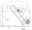
- FIG. 5 corresponds to that according to FIG. 4, but a counterweight 31 is provided there instead of the flow plate 28, which is connected to the tube 9.
- a bearing rod 33 Perpendicular to the axis of rotation 14 of the tube 9, a bearing rod 33 is welded upstream of the tube 9 to the horizontal tube section 10 at an angle of approximately 130 ° to the longitudinal axis 32 of the tube section 11.
- a large number of metallic ring disks 34 are placed on the bearing rod 33.
- a cotter pin 35 which is inserted through a bore in the area of the free end of the bearing rod 33, secures the ring disks 34.
- the number of ring disks 34 is selected in accordance with the required counterweight, such that the counterweight 31 is not when the washing container 4 is empty and with liquid acted upon duct shaft 2 safely raises the pipe 9 in the upper end position, in which it is held according to the mode of operation of the previously described embodiments by means of the holding unit 19 and released at a defined time.
- FIG. 6 shows a modification of the variant according to FIG. 5. This is shown without locking means, but it would also be conceivable to provide locking means according to the previously described embodiments in the configuration according to FIG.
- a counterweight 31 is also provided in the embodiment according to FIG. 6, which is designed as a displaceable metallic sleeve.
- a pipe socket 36 is welded perpendicular to the axis of rotation 14 at an angle of approximately 130 ° to the pipe section 10 such that it is in flow connection with the pipe 9 or the Pipe section 10 is.
- the pipe socket 36 is provided with an external thread 37 onto which the counterweight 31 can be screwed in a self-locking manner.
- the double arrows C make it clear that the counterweight 31 can be changed in position in both directions of the axis 38 of the pipe socket 36, so that the effective moment of the counterweight about the axis of rotation 14 can be set.
- the end of the pipe socket 36 facing away from the pipe section 10 is welded to a cover 39, whereby the pipe socket 36 presents itself as a cavity 40 which is only open towards the pipe 9.
- the result of this design is that the counterweight has a different size during operation of the flushing device. If there is no liquid in the rinsing container 4 or in the sewer shaft 2, that is to say no liquid in the region of the rinsing section, the counterweight 31 causes the tube to be raised to the inclined position shown in FIG.
- the rinsing device tilts counterclockwise into the position which is illustrated in relation to the embodiment according to FIG. 4 with respect to the pipe section 11.
- the rinsing process is started.
- the tube section 11 is only a small counterweight, which is only required for erection, while in the erected position a larger counterweight is effective when the liquid has flowed in, so that a hasty downward pivoting of the pipe section 11 is effectively prevented.
- the main application of the embodiment forms according to FIGS. 5 and 6 is the rinsing of rinsing sections, in particular in channels, in dry weather by means of external water or waste water, in particular domestic waste water. This allows the rinsing section to be continuously rinsed.
- fixing means for holding the tube are not required, as is illustrated for the embodiment according to FIG. 6.
- the rinsing device is suitable both for rinsing the rinsing section in dry weather and for rinsing after an accumulation of liquid in the area of the rinsing section.
- the locking means are not activated, whereby the flushing device according to the embodiment according to FIG. 6 is effective without locking means and flushes depending on the filling state of the flushing container. If, for example, due to a rain event, a liquid is stowed in the area of the rinsing section, or the like via the channel. the flushing tank is filled, the raised pipe end being held in this position by the element controlled by the liquid level being acted upon by the locking means and the element only actuating the locking means in the sense of an opening movement after the flushing section has run dry. If necessary, the external liquid supply to the washing container can be interrupted via the element controlled at a liquid level in the washing section
Landscapes
- Health & Medical Sciences (AREA)
- Life Sciences & Earth Sciences (AREA)
- Engineering & Computer Science (AREA)
- Hydrology & Water Resources (AREA)
- Public Health (AREA)
- Water Supply & Treatment (AREA)
- Sewage (AREA)
- Detergent Compositions (AREA)
- Cleaning In General (AREA)
Applications Claiming Priority (2)
| Application Number | Priority Date | Filing Date | Title |
|---|---|---|---|
| DE4342612 | 1993-12-14 | ||
| DE19934342612 DE4342612A1 (de) | 1993-12-14 | 1993-12-14 | Spülvorrichtung |
Publications (2)
| Publication Number | Publication Date |
|---|---|
| EP0658657A2 true EP0658657A2 (fr) | 1995-06-21 |
| EP0658657A3 EP0658657A3 (fr) | 1996-05-08 |
Family
ID=6504984
Family Applications (1)
| Application Number | Title | Priority Date | Filing Date |
|---|---|---|---|
| EP94119372A Withdrawn EP0658657A3 (fr) | 1993-12-14 | 1994-12-08 | Dispositif d'écoulement. |
Country Status (3)
| Country | Link |
|---|---|
| EP (1) | EP0658657A3 (fr) |
| CA (1) | CA2137874A1 (fr) |
| DE (1) | DE4342612A1 (fr) |
Cited By (4)
| Publication number | Priority date | Publication date | Assignee | Title |
|---|---|---|---|---|
| EP0898025A1 (fr) | 1997-08-15 | 1999-02-24 | Lothar Dipl.-Ing. Steinhardt | Appareil pour activer le mécanisme d'un dispositif de chasse d'eau |
| NL1009816C2 (nl) * | 1998-08-06 | 2000-02-15 | Wisa Bv | Werkwijze en systeem voor het afvoeren van een afvalstroom en daarbij toe te passen hevelinstallatie. |
| EP1279774A1 (fr) * | 2001-07-26 | 2003-01-29 | Manfred Weikopf | Méthode pour la gestion de vagues de cascade en des réseaux de canalisations |
| CN111424805A (zh) * | 2020-03-28 | 2020-07-17 | 郑州力达自动化控制有限公司 | 一种污水管路防结垢的方法 |
Families Citing this family (1)
| Publication number | Priority date | Publication date | Assignee | Title |
|---|---|---|---|---|
| CN114837289B (zh) * | 2022-04-21 | 2024-09-10 | 华中伟业建设集团有限公司 | 一种基于独立结构的装配式公路路基 |
Family Cites Families (6)
| Publication number | Priority date | Publication date | Assignee | Title |
|---|---|---|---|---|
| DE3900302A1 (de) * | 1989-01-07 | 1990-07-12 | Rolf Stahn | Verfahren und einrichtung zur vergleichmaessigung von abflusswassermengen aus regenrueckhaltebecken |
| CA1334611C (fr) * | 1989-09-28 | 1995-03-07 | George Heidebrecht | Systeme pour l'evacuation d'eaux usees |
| FR2654761B1 (fr) * | 1989-11-22 | 1992-10-23 | Wavin Bv | Dispositif de chasse pendulaire. |
| FR2654758B1 (fr) * | 1989-11-22 | 1992-03-27 | Wavin Bv | Dispositif de chasse pendulaire et de repartition de liquide. |
| CH680741A5 (fr) * | 1990-01-24 | 1992-10-30 | Nill Werner | |
| DE4212707A1 (de) * | 1992-04-16 | 1993-10-21 | Steinhardt Lothar | Kanalbauwerk mit Spüleinrichtung |
-
1993
- 1993-12-14 DE DE19934342612 patent/DE4342612A1/de not_active Ceased
-
1994
- 1994-12-08 EP EP94119372A patent/EP0658657A3/fr not_active Withdrawn
- 1994-12-12 CA CA 2137874 patent/CA2137874A1/fr not_active Abandoned
Cited By (7)
| Publication number | Priority date | Publication date | Assignee | Title |
|---|---|---|---|---|
| EP0898025A1 (fr) | 1997-08-15 | 1999-02-24 | Lothar Dipl.-Ing. Steinhardt | Appareil pour activer le mécanisme d'un dispositif de chasse d'eau |
| DE19735592A1 (de) * | 1997-08-15 | 1999-03-04 | Steinhardt Lothar | Vorrichtung zum Betätigen eines Mechanismus einer Spüleinrichtung |
| DE19735592C2 (de) * | 1997-08-15 | 2000-06-29 | Lothar Steinhardt | Vorrichtung zum Betätigen eines Mechanismus einer Spüleinrichtung |
| NL1009816C2 (nl) * | 1998-08-06 | 2000-02-15 | Wisa Bv | Werkwijze en systeem voor het afvoeren van een afvalstroom en daarbij toe te passen hevelinstallatie. |
| WO2000008267A1 (fr) * | 1998-08-06 | 2000-02-17 | Wisa B.V. | Procede et systeme permettant d'evacuer un flux residuaire et siphon associe |
| EP1279774A1 (fr) * | 2001-07-26 | 2003-01-29 | Manfred Weikopf | Méthode pour la gestion de vagues de cascade en des réseaux de canalisations |
| CN111424805A (zh) * | 2020-03-28 | 2020-07-17 | 郑州力达自动化控制有限公司 | 一种污水管路防结垢的方法 |
Also Published As
| Publication number | Publication date |
|---|---|
| DE4342612A1 (de) | 1995-06-22 |
| EP0658657A3 (fr) | 1996-05-08 |
| CA2137874A1 (fr) | 1995-06-15 |
Similar Documents
| Publication | Publication Date | Title |
|---|---|---|
| DE2440853B2 (de) | Spülklosett | |
| CH663045A5 (de) | Ablaufgarnitur fuer einen spuelkasten. | |
| DE3915076C2 (fr) | ||
| EP2006458B1 (fr) | Clapet de sortie pour une chasse d'eau | |
| DE3937685C2 (de) | Auslaßbauwerk mit einem Hochwasserverschluß für eine Abflußleitung eines Kanalnetzes oder dergleichen | |
| EP1866487A2 (fr) | Dispositif de retenue pour un regard d'egout | |
| EP0683276A2 (fr) | Dispositif de chasse pour W.C. | |
| DE4342612A1 (de) | Spülvorrichtung | |
| DE2323687C2 (de) | Rückstau- und Geruchsverschluß für Flüssigkeiten | |
| DE3510171A1 (de) | Fluessigkeitsrueckhalteeinrichtung fuer den einbau in einen fluessigkeitsspeicherraum | |
| DE9215972U1 (de) | Spülkasten-Ablaufventil | |
| EP1219753B1 (fr) | Dispositif pour la chasse pour nettoyer des égouts | |
| AT403819B (de) | Spülvorrichtung | |
| DE9016513U1 (de) | Vorrichtung zum Spülen eines Kanales | |
| EP0293513B1 (fr) | Procédé pour activer le mécanisme de fermeture d'une soupape commandée par flotteur d'une chambre de rinçage pour rincer un réservoir de stockage de liquide et dispositif pour appliquer ce procédé | |
| EP1039052B1 (fr) | Procédé pour la nettoyage d'un réservoir de stockage pour liquides, un réservoir de stockage pour liquides et un tambour de rinçage | |
| EP0619131B1 (fr) | Séparateur de liquide léger avec fermeture automatique | |
| DE2601282A1 (de) | Vorrichtung zum entleeren und selbsttaetigen fuellen eines wasserspeichers, insbesondere toilettenspuelkasten | |
| DE2337853C2 (de) | Rückstau- und Geruchsverschluß für Flüssigkelten, Insbesondere Abwässer | |
| DE9217369U1 (de) | Vorrichtung zur Verriegelung einer Spülklappe an einer Spülkammer eines Flüssigkeitsspeicherraumes | |
| DE69807377T2 (de) | Toilettenspülkasten | |
| DE10118549B4 (de) | Toilette mit Wasserspülung | |
| DE7607100U1 (de) | Vorrichtung zum entleeren eines sich selbsttaetig fuellenden wasserspeichers, insbesondere toilettenspuelkasten | |
| EP1580338B1 (fr) | Clapet de vidange pour un réservoir de chasse d'eau | |
| DE69921437T2 (de) | Ablaufvorrichtung für einen Spülkasten |
Legal Events
| Date | Code | Title | Description |
|---|---|---|---|
| PUAI | Public reference made under article 153(3) epc to a published international application that has entered the european phase |
Free format text: ORIGINAL CODE: 0009012 |
|
| AK | Designated contracting states |
Kind code of ref document: A2 Designated state(s): AT BE CH DE DK FR GB IT LI LU NL SE |
|
| PUAL | Search report despatched |
Free format text: ORIGINAL CODE: 0009013 |
|
| AK | Designated contracting states |
Kind code of ref document: A3 Designated state(s): AT BE CH DE DK FR GB IT LI LU NL SE |
|
| STAA | Information on the status of an ep patent application or granted ep patent |
Free format text: STATUS: THE APPLICATION IS DEEMED TO BE WITHDRAWN |
|
| 18D | Application deemed to be withdrawn |
Effective date: 19961109 |