EP0619175A2 - Vorrichtung zum sterilen Verschweissen von Kunststoffrohren unter hermetischen Abschluss - Google Patents
Vorrichtung zum sterilen Verschweissen von Kunststoffrohren unter hermetischen Abschluss Download PDFInfo
- Publication number
- EP0619175A2 EP0619175A2 EP94101709A EP94101709A EP0619175A2 EP 0619175 A2 EP0619175 A2 EP 0619175A2 EP 94101709 A EP94101709 A EP 94101709A EP 94101709 A EP94101709 A EP 94101709A EP 0619175 A2 EP0619175 A2 EP 0619175A2
- Authority
- EP
- European Patent Office
- Prior art keywords
- tube
- tubes
- holders
- lid
- plastic
- Prior art date
- Legal status (The legal status is an assumption and is not a legal conclusion. Google has not performed a legal analysis and makes no representation as to the accuracy of the status listed.)
- Withdrawn
Links
- 238000003466 welding Methods 0.000 title claims abstract description 24
- 230000000415 inactivating effect Effects 0.000 claims abstract description 11
- 239000012530 fluid Substances 0.000 claims description 11
- 238000010438 heat treatment Methods 0.000 claims description 7
- 238000000034 method Methods 0.000 claims description 6
- 238000003825 pressing Methods 0.000 claims description 4
- 238000002844 melting Methods 0.000 claims description 2
- 230000008018 melting Effects 0.000 claims description 2
- 238000005520 cutting process Methods 0.000 description 4
- 239000000463 material Substances 0.000 description 2
- 230000002441 reversible effect Effects 0.000 description 2
- 230000004913 activation Effects 0.000 description 1
- 239000007788 liquid Substances 0.000 description 1
- 238000004023 plastic welding Methods 0.000 description 1
Images


Classifications
-
- B—PERFORMING OPERATIONS; TRANSPORTING
- B29—WORKING OF PLASTICS; WORKING OF SUBSTANCES IN A PLASTIC STATE IN GENERAL
- B29C—SHAPING OR JOINING OF PLASTICS; SHAPING OF MATERIAL IN A PLASTIC STATE, NOT OTHERWISE PROVIDED FOR; AFTER-TREATMENT OF THE SHAPED PRODUCTS, e.g. REPAIRING
- B29C65/00—Joining or sealing of preformed parts, e.g. welding of plastics materials; Apparatus therefor
- B29C65/78—Means for handling the parts to be joined, e.g. for making containers or hollow articles, e.g. means for handling sheets, plates, web-like materials, tubular articles, hollow articles or elements to be joined therewith; Means for discharging the joined articles from the joining apparatus
- B29C65/7802—Positioning the parts to be joined, e.g. aligning, indexing or centring
-
- B—PERFORMING OPERATIONS; TRANSPORTING
- B29—WORKING OF PLASTICS; WORKING OF SUBSTANCES IN A PLASTIC STATE IN GENERAL
- B29C—SHAPING OR JOINING OF PLASTICS; SHAPING OF MATERIAL IN A PLASTIC STATE, NOT OTHERWISE PROVIDED FOR; AFTER-TREATMENT OF THE SHAPED PRODUCTS, e.g. REPAIRING
- B29C65/00—Joining or sealing of preformed parts, e.g. welding of plastics materials; Apparatus therefor
- B29C65/02—Joining or sealing of preformed parts, e.g. welding of plastics materials; Apparatus therefor by heating, with or without pressure
- B29C65/18—Joining or sealing of preformed parts, e.g. welding of plastics materials; Apparatus therefor by heating, with or without pressure using heated tools
- B29C65/20—Joining or sealing of preformed parts, e.g. welding of plastics materials; Apparatus therefor by heating, with or without pressure using heated tools with direct contact, e.g. using "mirror"
- B29C65/2046—Joining or sealing of preformed parts, e.g. welding of plastics materials; Apparatus therefor by heating, with or without pressure using heated tools with direct contact, e.g. using "mirror" using a welding mirror which also cuts the parts to be joined, e.g. for sterile welding
-
- B—PERFORMING OPERATIONS; TRANSPORTING
- B29—WORKING OF PLASTICS; WORKING OF SUBSTANCES IN A PLASTIC STATE IN GENERAL
- B29C—SHAPING OR JOINING OF PLASTICS; SHAPING OF MATERIAL IN A PLASTIC STATE, NOT OTHERWISE PROVIDED FOR; AFTER-TREATMENT OF THE SHAPED PRODUCTS, e.g. REPAIRING
- B29C65/00—Joining or sealing of preformed parts, e.g. welding of plastics materials; Apparatus therefor
- B29C65/02—Joining or sealing of preformed parts, e.g. welding of plastics materials; Apparatus therefor by heating, with or without pressure
- B29C65/18—Joining or sealing of preformed parts, e.g. welding of plastics materials; Apparatus therefor by heating, with or without pressure using heated tools
- B29C65/20—Joining or sealing of preformed parts, e.g. welding of plastics materials; Apparatus therefor by heating, with or without pressure using heated tools with direct contact, e.g. using "mirror"
- B29C65/2053—Joining or sealing of preformed parts, e.g. welding of plastics materials; Apparatus therefor by heating, with or without pressure using heated tools with direct contact, e.g. using "mirror" characterised by special ways of bringing the welding mirrors into position
- B29C65/2061—Joining or sealing of preformed parts, e.g. welding of plastics materials; Apparatus therefor by heating, with or without pressure using heated tools with direct contact, e.g. using "mirror" characterised by special ways of bringing the welding mirrors into position by sliding
-
- B—PERFORMING OPERATIONS; TRANSPORTING
- B29—WORKING OF PLASTICS; WORKING OF SUBSTANCES IN A PLASTIC STATE IN GENERAL
- B29C—SHAPING OR JOINING OF PLASTICS; SHAPING OF MATERIAL IN A PLASTIC STATE, NOT OTHERWISE PROVIDED FOR; AFTER-TREATMENT OF THE SHAPED PRODUCTS, e.g. REPAIRING
- B29C65/00—Joining or sealing of preformed parts, e.g. welding of plastics materials; Apparatus therefor
- B29C65/78—Means for handling the parts to be joined, e.g. for making containers or hollow articles, e.g. means for handling sheets, plates, web-like materials, tubular articles, hollow articles or elements to be joined therewith; Means for discharging the joined articles from the joining apparatus
- B29C65/7841—Holding or clamping means for handling purposes
-
- B—PERFORMING OPERATIONS; TRANSPORTING
- B29—WORKING OF PLASTICS; WORKING OF SUBSTANCES IN A PLASTIC STATE IN GENERAL
- B29C—SHAPING OR JOINING OF PLASTICS; SHAPING OF MATERIAL IN A PLASTIC STATE, NOT OTHERWISE PROVIDED FOR; AFTER-TREATMENT OF THE SHAPED PRODUCTS, e.g. REPAIRING
- B29C66/00—General aspects of processes or apparatus for joining preformed parts
- B29C66/001—Joining in special atmospheres
- B29C66/0012—Joining in special atmospheres characterised by the type of environment
- B29C66/0018—Joining in special atmospheres characterised by the type of environment being sterile
-
- B—PERFORMING OPERATIONS; TRANSPORTING
- B29—WORKING OF PLASTICS; WORKING OF SUBSTANCES IN A PLASTIC STATE IN GENERAL
- B29C—SHAPING OR JOINING OF PLASTICS; SHAPING OF MATERIAL IN A PLASTIC STATE, NOT OTHERWISE PROVIDED FOR; AFTER-TREATMENT OF THE SHAPED PRODUCTS, e.g. REPAIRING
- B29C66/00—General aspects of processes or apparatus for joining preformed parts
- B29C66/01—General aspects dealing with the joint area or with the area to be joined
- B29C66/05—Particular design of joint configurations
- B29C66/10—Particular design of joint configurations particular design of the joint cross-sections
- B29C66/11—Joint cross-sections comprising a single joint-segment, i.e. one of the parts to be joined comprising a single joint-segment in the joint cross-section
- B29C66/114—Single butt joints
- B29C66/1142—Single butt to butt joints
-
- B—PERFORMING OPERATIONS; TRANSPORTING
- B29—WORKING OF PLASTICS; WORKING OF SUBSTANCES IN A PLASTIC STATE IN GENERAL
- B29C—SHAPING OR JOINING OF PLASTICS; SHAPING OF MATERIAL IN A PLASTIC STATE, NOT OTHERWISE PROVIDED FOR; AFTER-TREATMENT OF THE SHAPED PRODUCTS, e.g. REPAIRING
- B29C66/00—General aspects of processes or apparatus for joining preformed parts
- B29C66/50—General aspects of joining tubular articles; General aspects of joining long products, i.e. bars or profiled elements; General aspects of joining single elements to tubular articles, hollow articles or bars; General aspects of joining several hollow-preforms to form hollow or tubular articles
- B29C66/51—Joining tubular articles, profiled elements or bars; Joining single elements to tubular articles, hollow articles or bars; Joining several hollow-preforms to form hollow or tubular articles
- B29C66/52—Joining tubular articles, bars or profiled elements
- B29C66/522—Joining tubular articles
- B29C66/5221—Joining tubular articles for forming coaxial connections, i.e. the tubular articles to be joined forming a zero angle relative to each other
-
- B—PERFORMING OPERATIONS; TRANSPORTING
- B29—WORKING OF PLASTICS; WORKING OF SUBSTANCES IN A PLASTIC STATE IN GENERAL
- B29C—SHAPING OR JOINING OF PLASTICS; SHAPING OF MATERIAL IN A PLASTIC STATE, NOT OTHERWISE PROVIDED FOR; AFTER-TREATMENT OF THE SHAPED PRODUCTS, e.g. REPAIRING
- B29C66/00—General aspects of processes or apparatus for joining preformed parts
- B29C66/70—General aspects of processes or apparatus for joining preformed parts characterised by the composition, physical properties or the structure of the material of the parts to be joined; Joining with non-plastics material
- B29C66/73—General aspects of processes or apparatus for joining preformed parts characterised by the composition, physical properties or the structure of the material of the parts to be joined; Joining with non-plastics material characterised by the intensive physical properties of the material of the parts to be joined, by the optical properties of the material of the parts to be joined, by the extensive physical properties of the parts to be joined, by the state of the material of the parts to be joined or by the material of the parts to be joined being a thermoplastic or a thermoset
- B29C66/739—General aspects of processes or apparatus for joining preformed parts characterised by the composition, physical properties or the structure of the material of the parts to be joined; Joining with non-plastics material characterised by the intensive physical properties of the material of the parts to be joined, by the optical properties of the material of the parts to be joined, by the extensive physical properties of the parts to be joined, by the state of the material of the parts to be joined or by the material of the parts to be joined being a thermoplastic or a thermoset characterised by the material of the parts to be joined being a thermoplastic or a thermoset
- B29C66/7392—General aspects of processes or apparatus for joining preformed parts characterised by the composition, physical properties or the structure of the material of the parts to be joined; Joining with non-plastics material characterised by the intensive physical properties of the material of the parts to be joined, by the optical properties of the material of the parts to be joined, by the extensive physical properties of the parts to be joined, by the state of the material of the parts to be joined or by the material of the parts to be joined being a thermoplastic or a thermoset characterised by the material of the parts to be joined being a thermoplastic or a thermoset characterised by the material of at least one of the parts being a thermoplastic
- B29C66/73921—General aspects of processes or apparatus for joining preformed parts characterised by the composition, physical properties or the structure of the material of the parts to be joined; Joining with non-plastics material characterised by the intensive physical properties of the material of the parts to be joined, by the optical properties of the material of the parts to be joined, by the extensive physical properties of the parts to be joined, by the state of the material of the parts to be joined or by the material of the parts to be joined being a thermoplastic or a thermoset characterised by the material of the parts to be joined being a thermoplastic or a thermoset characterised by the material of at least one of the parts being a thermoplastic characterised by the materials of both parts being thermoplastics
-
- B—PERFORMING OPERATIONS; TRANSPORTING
- B29—WORKING OF PLASTICS; WORKING OF SUBSTANCES IN A PLASTIC STATE IN GENERAL
- B29L—INDEXING SCHEME ASSOCIATED WITH SUBCLASS B29C, RELATING TO PARTICULAR ARTICLES
- B29L2023/00—Tubular articles
- B29L2023/005—Hoses, i.e. flexible
- B29L2023/006—Flexible liners
-
- B—PERFORMING OPERATIONS; TRANSPORTING
- B29—WORKING OF PLASTICS; WORKING OF SUBSTANCES IN A PLASTIC STATE IN GENERAL
- B29L—INDEXING SCHEME ASSOCIATED WITH SUBCLASS B29C, RELATING TO PARTICULAR ARTICLES
- B29L2023/00—Tubular articles
- B29L2023/22—Tubes or pipes, i.e. rigid
-
- Y—GENERAL TAGGING OF NEW TECHNOLOGICAL DEVELOPMENTS; GENERAL TAGGING OF CROSS-SECTIONAL TECHNOLOGIES SPANNING OVER SEVERAL SECTIONS OF THE IPC; TECHNICAL SUBJECTS COVERED BY FORMER USPC CROSS-REFERENCE ART COLLECTIONS [XRACs] AND DIGESTS
- Y10—TECHNICAL SUBJECTS COVERED BY FORMER USPC
- Y10T—TECHNICAL SUBJECTS COVERED BY FORMER US CLASSIFICATION
- Y10T156/00—Adhesive bonding and miscellaneous chemical manufacture
- Y10T156/10—Methods of surface bonding and/or assembly therefor
- Y10T156/1052—Methods of surface bonding and/or assembly therefor with cutting, punching, tearing or severing
- Y10T156/1054—Methods of surface bonding and/or assembly therefor with cutting, punching, tearing or severing and simultaneously bonding [e.g., cut-seaming]
-
- Y—GENERAL TAGGING OF NEW TECHNOLOGICAL DEVELOPMENTS; GENERAL TAGGING OF CROSS-SECTIONAL TECHNOLOGIES SPANNING OVER SEVERAL SECTIONS OF THE IPC; TECHNICAL SUBJECTS COVERED BY FORMER USPC CROSS-REFERENCE ART COLLECTIONS [XRACs] AND DIGESTS
- Y10—TECHNICAL SUBJECTS COVERED BY FORMER USPC
- Y10T—TECHNICAL SUBJECTS COVERED BY FORMER US CLASSIFICATION
- Y10T156/00—Adhesive bonding and miscellaneous chemical manufacture
- Y10T156/10—Methods of surface bonding and/or assembly therefor
- Y10T156/1052—Methods of surface bonding and/or assembly therefor with cutting, punching, tearing or severing
- Y10T156/1062—Prior to assembly
- Y10T156/1066—Cutting to shape joining edge surfaces only
-
- Y—GENERAL TAGGING OF NEW TECHNOLOGICAL DEVELOPMENTS; GENERAL TAGGING OF CROSS-SECTIONAL TECHNOLOGIES SPANNING OVER SEVERAL SECTIONS OF THE IPC; TECHNICAL SUBJECTS COVERED BY FORMER USPC CROSS-REFERENCE ART COLLECTIONS [XRACs] AND DIGESTS
- Y10—TECHNICAL SUBJECTS COVERED BY FORMER USPC
- Y10T—TECHNICAL SUBJECTS COVERED BY FORMER US CLASSIFICATION
- Y10T156/00—Adhesive bonding and miscellaneous chemical manufacture
- Y10T156/12—Surface bonding means and/or assembly means with cutting, punching, piercing, severing or tearing
- Y10T156/1313—Cutting element simultaneously bonds [e.g., cut seaming]
-
- Y—GENERAL TAGGING OF NEW TECHNOLOGICAL DEVELOPMENTS; GENERAL TAGGING OF CROSS-SECTIONAL TECHNOLOGIES SPANNING OVER SEVERAL SECTIONS OF THE IPC; TECHNICAL SUBJECTS COVERED BY FORMER USPC CROSS-REFERENCE ART COLLECTIONS [XRACs] AND DIGESTS
- Y10—TECHNICAL SUBJECTS COVERED BY FORMER USPC
- Y10T—TECHNICAL SUBJECTS COVERED BY FORMER US CLASSIFICATION
- Y10T156/00—Adhesive bonding and miscellaneous chemical manufacture
- Y10T156/12—Surface bonding means and/or assembly means with cutting, punching, piercing, severing or tearing
- Y10T156/1317—Means feeding plural workpieces to be joined
- Y10T156/1322—Severing before bonding or assembling of parts
- Y10T156/1326—Severing means or member secured thereto also bonds
-
- Y—GENERAL TAGGING OF NEW TECHNOLOGICAL DEVELOPMENTS; GENERAL TAGGING OF CROSS-SECTIONAL TECHNOLOGIES SPANNING OVER SEVERAL SECTIONS OF THE IPC; TECHNICAL SUBJECTS COVERED BY FORMER USPC CROSS-REFERENCE ART COLLECTIONS [XRACs] AND DIGESTS
- Y10—TECHNICAL SUBJECTS COVERED BY FORMER USPC
- Y10T—TECHNICAL SUBJECTS COVERED BY FORMER US CLASSIFICATION
- Y10T156/00—Adhesive bonding and miscellaneous chemical manufacture
- Y10T156/12—Surface bonding means and/or assembly means with cutting, punching, piercing, severing or tearing
- Y10T156/1378—Cutter actuated by or secured to bonding element
Definitions
- U.S. Patent 4,753,697 discloses an arrangement in Figure 3 wherein an aligning bar 24 is suspended from a rail 26 so that the aligning bar could be located in the space between the tube holders and so that the tubes could be moved forward into contact with the aligning bar.
- the aligning bar would form a means of locating the tubes with respect to each other. After this locating step is performed, the aligning bar is moved out of its position of contact with the tubes.
- Parent application Serial No. 965,875 discloses a total containment device for the con- nect/disconnect of plastic tubes. That device includes movable wall mounted to each clamp base. The wall serves as a locator for properly positioning a tube in its associated clamp base. Each base includes a clamp lid which has an inactivating member so that upon movement of the lid to its closing position the wall is automatically moved out of contact with its tube to expose the tubes for the later heating and welding steps.
- This arrangement has the advantage of automatically removing the movable wall away from the tubes upon the closing of the lid and does not rely upon other operations, such as would be required to move the aligning bar out of contact with the tubes as in U.S. Patent 4,753,697.
- the present invention is directed to these aspects of parent application Serial No. 965,875.
- An object of this invention is to provide a sterile containment welding device which includes some means for properly positioning the plastic tubes for the later heating and welding steps.
- a further object of this invention is to provide such a device which utilizes features disclosed in parent application Serial No. 965,875 for automatically removing the locating member after the tubes have been properly positioned.
- a still further object of this invention is to provide such a device which can be used for properly positioning fluid filled tubes, particularly tubes mounted in a bent condition.
- a sterile containment welding device for plastic tubes comprises a pair of side by side spaced tube holders.
- Each of the tube holders includes a clamp base and a clamp lid with a pocket extending completely across the clamp base so that a plastic tube may be inserted in the pocket and clamped in the holder when the clamp lid is moved to its closed position.
- the pockets of the side by side tube holders are alignable with each other to permit a plastic tube in one of the holders to be welded to a plastic tube in the other holder after the tubes have been heated.
- a tube locating member is mounted at the end of each pocket in the space between the holders.
- Each tube locating member has a wall located in the space between the holders with the wall disposed beyond and across its pocket for positioning a plastic tube in its proper location during the later welding step. This is accomplished by moving the tube into contact with the wall.
- An inactivating member is mounted to its lid and is movable into contact with its tube locating member for moving the tube locating member out of contact with the plastic tube upon the closing of the lid to expose the tubes and permit them to be later heated and welded together.
- the invention may be practiced by utilizing a spring to bias the tube locating member in its positioning orientation.
- the tube locating member may be U-shaped with the bight of the U being the locating wall and with the legs of the U having holes into which pivot pins are inserted to permit the tube locating member to be pivoted out of contact with the tube upon the closing of the lid.
- Figure 1 illustrates a sterile containment welding device 10 in accordance with this invention.
- Device 10 is generally of the structure of the device illustrated and described in parent application Serial No. 965,875 the details of which are incorporated herein by reference thereto. Accordingly, device 10 will be described only with respect to those details as is necessary for an understanding of the present invention.
- device 10 includes a pair of side by side spaced tube holders 12,12.
- Each of the tube holders includes a clamp base 14 and a clamp lid 16 pivotally connected to the clamp base.
- a pocket or groove 18 extends completely across each clamp base so that a plastic tube T may be inserted in the pocket and clamped to its holder when clamp lid 16 is pivoted to its closed position.
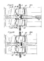
- Figure 1 illustrates one of the clamp holders with its lid 16 in the open position at the upper portion of Figure 1 while the lower portion of Figure 1 illustrates the clamp holder with the lid 16 in its closed clamping position.
- Figures 2-3 show the lid 16 open and
- Figures 4-5 show the lid closed.
- the clamp holders 12,12 are mounted spaced from each other. As described in the parent application, the clamp holders can be moved toward and away from each other to change the spacing. Initially, the spacing would be greater when the tubes T,T are inserted into each clamp holder. It is essential that the tubes be properly positioned in the clamp holders so that when the clamp holders are then pivoted toward each other the tubes are properly aligned and spaced for the later heating and welding operations.
- the present invention incorporates a tube locating member 20 mounted to each clamp base 14 at the end of each pocket 18 in the spacing between the tube holders.
- FIG 8 illustrates a tube locating member 20.
- tube locating member 20 is generally U-shaped with the bight of the U being a flat wall 22 and with a pair of legs 24 extending outwardly from wall 22.
- the inner surface of tube locating member 20 has an inwardly directed shoulder 26 at the junction of each leg 24 with the bight or wall 22. This creates a recess at the inner surface of wall 22 which would be dimensioned to receive a tube T.
- the shoulders 26 would provide some clearance to accommodate the plastic tube T as it is pressed into the recess at the inner surface of locating wall 22.
- each leg 24 is provided with a hole 28 extending completely through the leg.
- the clamp base 14 includes a cut-away portion 30 which would accommodate tube locating member 20 when the tube locating member 20 is rotated from its tube locating position shown in the upper portion of Figure 1 and in Figures 2-3 to its inactive position as shown in the lower portion of Figure 1 and in Figures 4-5.
- the pivotal movement of tube locating member 20 is achieved by means of pins 32 mounted in clamp base 14 and extending into the holes 28 in legs 24 of tube locating member 20.
- Tube locating member 20 is biased upwardly to its tube locating position by any suitable means such as spring 34.
- spring 34 would urge tube locating member 20 to a position where its end wall 22 would be disposed outwardly from, but across the pocket 18.
- a tube T would be inserted into pocket 18 and moved inwardly until the tube contacts the recess at the inner surface of tube locating wall 22. This assures the proper position of tube T.
- lid 16 After a tube T is moved into contact with wall 22, lid 16 would then be moved to its closed clamping condition.
- An inactivating member 36 such as a flange or other projection is mounted on the inner surface of lid 16 and is located so that when lid 16 is pivoted to its closed position inactivating member 36 contacts tube locating member 20 and the continued downward clamping movement of lid 16 urges tube locating member 20 to pivot downwardly in opposition to the force from spring 34 so that the tube locating member is pivoted out of contact with tube T and into a location where it would not interfere with the later heating and welding operations.
- Figures 4-5 for example, illustrate tube locating member 20 when pivoted to the inactive position.
- Device 10 may be used for welding any type of plastic tubes together. Device 10, however, is particularly advantageous in the welding of fluid filled tubes. Device 10 overcomes serious limitations encountered by the prior art in attempting to properly locate such fluid filled tubes. Because of the varying amount of plastic involved in the end of the distal tube, device 10 and particularly tube locating member 20 avoid the excess material problem of a single tube and also eliminate the residual liquid problem by using the wall 22 to locate the ends of a tube, particularly a fluid filled bent tube, such as illustrated herein.
- FIG. 6-7 illustrate a wafer 38 having a pair of wings 40,40 and may generally of the type of structure shown and described in U.S. Patent No. 5,158,630, the details of which are incorporated herein by reference thereto.
- any suitable structure may be used for wafer 38 including the various structures described in co-pending application Serial No. 764,249, filed September 23, 1991, the details of which are incorporated herein by reference thereto.
- the wafer may operate by cutting through the bent tubes as illustrated in Figure 7 or may use a melt- wipe type of operation such as described in parent application Serial No 965,875 and the parent applications referred to therein.
- clamp holders 12,12 are moved closer together and the cut tube sections resulting from the cutting operation are pressed into contact with each other to weld each tube section from one holder to a respective tube section of the other holder in a known manner.
- FIG. 1 utilizes a pair of tube holders 12 which are pivotally mounted to be moved toward and away from each other. It is to be understood, however, that the invention may be practiced with other forms of tube holders.
- Figures 9-11 illustrate a device 10A wherein each tube holder 12 is mounted for moving toward and away from each other along a straight line rather than being pivotally mounted for movement along an arc. Any suitable means may be used for moving the tube holders 12.
- Figure 11 best illustrates one form of movement means.
- each tube holder 12 is mounted to a bearing block 42.
- Each bearing block 42 has a hole extending completely therethrough with a reverse thread lead screw 44 threadably engaged in each hole.
- Lead screw 44 has a gear 46 centrally mounted thereon which is in engagement with a worm gear 48 driven by reversible motor M.
- the holders 12,12 may be moved toward and away from each other in accordance with the direction of movement of motor M.
- Figure 9 illustrates the position of the various components of device 10A when the tubes T,T are spaced apart from each other but the clamp lids 16,16 are closed to move locating member 20 to its inactive position which is shown in Figure 11. As illustrated in this initial positioning wafer 38 is approaching the space between the aligned parallel tube holders 12,12.
- Figure 10 illustrates a further sequence in operation wherein activation of motor M causes the tube holders 12,12 to be moved toward each other so that the ends of the tubes touch. In this position wafer 38 is shown cutting through the tubes. After wafer 38 passes through the tubes motor M causes the tube holder 12,12 to be moved further closer together so that the heated tube ends contact and are welded together as previously described.
- Figure 1 illustrates a device wherein each tube holder includes a single groove or pocket for receiving a single tube.
- Other arrangements may be used which would include, for example, multiple grooves or pockets wherein the tube holders are laterally shifted to realign pockets of one holder with pockets of another holder.
- the present invention is particularly advantageous with bent fluid filled tubes the invention may be practiced where there is no fluid in the tubes or where the tubes are placed in an unbent straight condition.
- the invention may be summarized as follows:
Landscapes
- Engineering & Computer Science (AREA)
- Mechanical Engineering (AREA)
- Health & Medical Sciences (AREA)
- Toxicology (AREA)
- Lining Or Joining Of Plastics Or The Like (AREA)
- Closing Of Containers (AREA)
- Vacuum Packaging (AREA)
- Shaping Of Tube Ends By Bending Or Straightening (AREA)
Applications Claiming Priority (2)
| Application Number | Priority Date | Filing Date | Title |
|---|---|---|---|
| US29704 | 1993-03-11 | ||
| US08/029,704 US5256229A (en) | 1992-10-23 | 1993-03-11 | Sterile containment welding device for plastic tubes |
Publications (2)
| Publication Number | Publication Date |
|---|---|
| EP0619175A2 true EP0619175A2 (de) | 1994-10-12 |
| EP0619175A3 EP0619175A3 (de) | 1996-03-13 |
Family
ID=21850436
Family Applications (1)
| Application Number | Title | Priority Date | Filing Date |
|---|---|---|---|
| EP94101709A Withdrawn EP0619175A3 (de) | 1993-03-11 | 1994-02-04 | Vorrichtung zum sterilen Verschweissen von Kunststoffrohren unter hermetischen Abschluss. |
Country Status (4)
| Country | Link |
|---|---|
| US (1) | US5256229A (de) |
| EP (1) | EP0619175A3 (de) |
| JP (1) | JPH072202A (de) |
| CA (1) | CA2114878C (de) |
Cited By (6)
| Publication number | Priority date | Publication date | Assignee | Title |
|---|---|---|---|---|
| EP0723851A3 (de) * | 1995-01-18 | 1998-01-21 | Denco, Inc. | Gerät zum hermetischen Verbinden/Abschliessen |
| EP0778123A3 (de) * | 1995-12-08 | 1998-02-18 | Terumo Kabushiki Kaisha | Rohrverbindungsvorrichtung |
| US6913056B2 (en) | 2002-01-31 | 2005-07-05 | Baxter International Inc. | Apparatus and method for connecting and disconnecting flexible tubing |
| US7275543B2 (en) | 2002-09-20 | 2007-10-02 | Baxter International Inc. | Coupler member for joining dissimilar materials |
| US8162021B2 (en) | 2004-03-29 | 2012-04-24 | Baxter International | Apparatus for sterile connection of tubing |
| US10919235B2 (en) | 2017-06-07 | 2021-02-16 | Fenwal, Inc. | Apparatus and method for mechanically opening a connection site |
Families Citing this family (26)
| Publication number | Priority date | Publication date | Assignee | Title |
|---|---|---|---|---|
| US5674333A (en) * | 1992-10-23 | 1997-10-07 | Denco, Inc. | Total containment welding of plastic tubes |
| US5855731A (en) * | 1997-09-17 | 1999-01-05 | Denco, Inc. | Sterile containment welding device for plastic tubes |
| US6020574A (en) * | 1998-03-09 | 2000-02-01 | Denco, Inc. | Sterile containment welding device with self-monitoring heater unit for plastic tubes |
| US6485593B1 (en) * | 1998-10-26 | 2002-11-26 | Kurt J. Christoffersen | Sterile docking apparatus and method of use |
| US6696018B2 (en) | 2001-11-14 | 2004-02-24 | Electron Process Company, Llc | System and method for sterilization of biological connections |
| US20030226857A1 (en) * | 2002-04-12 | 2003-12-11 | Hyclone Laboratories, Inc. | Systems for forming sterile fluid connections and methods of use |
| US7398813B2 (en) | 2006-07-31 | 2008-07-15 | Denco Inc. | Device for welding plastic tubes |
| US7731914B2 (en) * | 2007-07-11 | 2010-06-08 | Denco, Inc. | Ozone infection control device |
| JP5010635B2 (ja) | 2009-03-18 | 2012-08-29 | 三菱重工業株式会社 | 熱交換器 |
| US8708019B2 (en) * | 2009-06-10 | 2014-04-29 | Genesis Bps, Llc | Device for welding plastic tubes |
| US8066269B2 (en) * | 2009-06-22 | 2011-11-29 | Genesis Bps, Llc | Clamp locking mechanism in device for welding plastic tubes |
| EP2420286A1 (de) * | 2010-08-18 | 2012-02-22 | Fresenius Kabi Deutschland GmbH | Verfahren und Vorrichtung zum sterilen Verbinden von Schläuchen |
| US8448992B2 (en) | 2011-02-16 | 2013-05-28 | Fenwal, Inc. | Sterile docking device, medical fluid flow system with sterile docking device and method of using same |
| JP5771066B2 (ja) * | 2011-05-18 | 2015-08-26 | 株式会社ジェイ・エム・エス | チューブ溶断溶着装置 |
| WO2013096038A1 (en) | 2011-12-21 | 2013-06-27 | Fenwal, Inc. | Fluid flow conduits and apparatus and methods for making and joining fluid conduits |
| WO2013130636A2 (en) | 2012-02-28 | 2013-09-06 | Hyclone Laboratories, Inc. | Systems and containers for sterilizing a fluid |
| US9308709B2 (en) | 2013-06-06 | 2016-04-12 | Fenwal, Inc. | Bonding apparatus and method |
| US9440396B2 (en) | 2014-06-19 | 2016-09-13 | Fenwal, Inc. | Sterile connection device for making multiple connections |
| US9839582B2 (en) | 2014-12-02 | 2017-12-12 | Fenwal, Inc. | Sterile connection syringe assemblies |
| US12179466B2 (en) | 2020-08-25 | 2024-12-31 | Fenwal, Inc. | System and method for the automated opening of a sterile tubing weld |
| EP4035723A1 (de) | 2021-01-25 | 2022-08-03 | Fenwal, Inc. | Sterile schlauchverbindung |
| US12478551B2 (en) | 2022-03-10 | 2025-11-25 | Terumo Bct, Inc. | Collection bottle with integrated cap, handle, and shield features |
| US12458740B2 (en) | 2022-03-10 | 2025-11-04 | Terumo Bct, Inc. | Modular serviceability sleds and interconnections |
| US12521474B2 (en) | 2022-03-10 | 2026-01-13 | Terumo Bct, Inc. | Soft cassette with integrated features |
| US12379916B2 (en) | 2022-03-10 | 2025-08-05 | Terumo Bct, Inc. | Communications and operation control of apheresis systems |
| US12599710B2 (en) | 2022-03-10 | 2026-04-14 | Terumo Bct, Inc. | Methods and interfaces for providing donation process feedback |
Family Cites Families (17)
| Publication number | Priority date | Publication date | Assignee | Title |
|---|---|---|---|---|
| US2384014A (en) * | 1943-05-03 | 1945-09-04 | Thomson Gibb Electric Welding | Welding apparatus |
| DE2112167A1 (de) * | 1971-03-13 | 1972-11-16 | Pfaff Ind Masch | Schweissmaschine fuer thermoplastische Bestandteile aufweisende Materialien |
| DE2128922C3 (de) * | 1971-06-11 | 1974-01-03 | Bielomatik Leuze & Co, 7442 Neuffen | Verfahren und Vorrichtung zum Verschweißen von Kunststoffteilen zu einem Rahmen |
| DE2350841C3 (de) * | 1972-11-20 | 1978-12-14 | Deutsche Semperit Gmbh, 8000 Muenchen | Verfahren zum Stoßverbinden von Lagen aus plastisch verformbarem Material, insbesondere von kautschukierten Stahldrahtlagen |
| JPS526779A (en) * | 1975-07-08 | 1977-01-19 | Yokohama Rubber Co Ltd | Method and apparatus for jointing material in sheet form |
| US4352708A (en) * | 1980-09-08 | 1982-10-05 | Mcelroy Arthur H | Defined force fusion machine for joining plastic pipe |
| US4521263A (en) * | 1982-08-16 | 1985-06-04 | E. I. Du Pont De Nemours And Company | Automatic splicing device and process |
| GB8615517D0 (en) * | 1986-06-25 | 1986-07-30 | Fusion Equipment Ltd | Butt-welding of pipes |
| US4753697A (en) * | 1987-02-24 | 1988-06-28 | Denco, Inc. | Total-containment sterile process and system |
| US4793880A (en) * | 1987-05-18 | 1988-12-27 | Denco, Inc. | Sterile welding of plastic tubes |
| US5279685A (en) * | 1990-08-20 | 1994-01-18 | Denco, Inc. | Total containment device for connect/disconnect of plastic tubes |
| US5158630A (en) * | 1990-08-20 | 1992-10-27 | Denco, Inc. | Total containment welding or plastic tubes |
| US5141592A (en) * | 1990-08-20 | 1992-08-25 | Denco, Inc. | Sterile entry/exit total containment process for closed systems using plastic tubes |
| US5209800A (en) * | 1990-08-20 | 1993-05-11 | Denco, Inc. | Total containment welding of plastic tubes |
| US5244522A (en) * | 1990-10-29 | 1993-09-14 | Denco Inc. | Total containment welding of plastic tubes |
| EP0485706B1 (de) * | 1990-11-15 | 1994-12-14 | RAFELD KUNSTSTOFFTECHNIK GmbH & Co. KG | Sanitär- und Heizungsrohrsystem, vollständig oder überwiegend bestehend aus Kunststoff, insbesondere Polypropylen, für die Wasserversorgung |
| CA2063169A1 (en) * | 1991-05-31 | 1992-12-01 | John B. Shaposka | Sterile welding of plastic tubes |
-
1993
- 1993-03-11 US US08/029,704 patent/US5256229A/en not_active Expired - Lifetime
-
1994
- 1994-02-03 CA CA002114878A patent/CA2114878C/en not_active Expired - Lifetime
- 1994-02-04 EP EP94101709A patent/EP0619175A3/de not_active Withdrawn
- 1994-03-10 JP JP6039660A patent/JPH072202A/ja active Pending
Cited By (11)
| Publication number | Priority date | Publication date | Assignee | Title |
|---|---|---|---|---|
| EP0723851A3 (de) * | 1995-01-18 | 1998-01-21 | Denco, Inc. | Gerät zum hermetischen Verbinden/Abschliessen |
| EP0778123A3 (de) * | 1995-12-08 | 1998-02-18 | Terumo Kabushiki Kaisha | Rohrverbindungsvorrichtung |
| US5802689A (en) * | 1995-12-08 | 1998-09-08 | Terumo Kabushiki Kaisha | Tube connecting apparatus |
| US6913056B2 (en) | 2002-01-31 | 2005-07-05 | Baxter International Inc. | Apparatus and method for connecting and disconnecting flexible tubing |
| US7226649B2 (en) | 2002-01-31 | 2007-06-05 | Baxter International Inc. | Laser weldable flexible medical tubings, films and assemblies thereof |
| US7459054B2 (en) | 2002-01-31 | 2008-12-02 | Baxter International Inc. | Apparatus and method for connecting and disconnecting flexible tubing |
| US8146642B2 (en) | 2002-01-31 | 2012-04-03 | Baxter International Inc. | Apparatus and method for connecting and disconnecting flexible tubing |
| US7275543B2 (en) | 2002-09-20 | 2007-10-02 | Baxter International Inc. | Coupler member for joining dissimilar materials |
| US8162021B2 (en) | 2004-03-29 | 2012-04-24 | Baxter International | Apparatus for sterile connection of tubing |
| US10919235B2 (en) | 2017-06-07 | 2021-02-16 | Fenwal, Inc. | Apparatus and method for mechanically opening a connection site |
| US11325321B2 (en) | 2017-06-07 | 2022-05-10 | Fenwal, Inc. | Apparatus and method for mechanically opening a connection site |
Also Published As
| Publication number | Publication date |
|---|---|
| JPH072202A (ja) | 1995-01-06 |
| CA2114878A1 (en) | 1994-09-12 |
| EP0619175A3 (de) | 1996-03-13 |
| CA2114878C (en) | 2005-04-19 |
| US5256229A (en) | 1993-10-26 |
Similar Documents
| Publication | Publication Date | Title |
|---|---|---|
| EP0619175A2 (de) | Vorrichtung zum sterilen Verschweissen von Kunststoffrohren unter hermetischen Abschluss | |
| US4897138A (en) | Sealing of plastic tubes | |
| US5837967A (en) | Burner holder for mechanized or automated arc welding or cutting torches, especially machine and/or robot torches | |
| US8066269B2 (en) | Clamp locking mechanism in device for welding plastic tubes | |
| JPH06197986A (ja) | プラスチックチューブを選択的に連結・分離する装置 | |
| CA2118426A1 (en) | Total containment welding of plastic tubes | |
| CN100457431C (zh) | 管接合装置 | |
| JP3865434B2 (ja) | 樹脂管用融着機 | |
| BRPI0916742B1 (pt) | ferramenta de solda a laser com um laser de fibra | |
| US4542892A (en) | Poly-pipe fusion machine | |
| FI906055A0 (fi) | Uppvaermningsanordning foer svetsanordning. | |
| US3017314A (en) | Apparatus for producing plastic bags | |
| EP0723851A2 (de) | Gerät zum hermetischen Verbinden/Abschliessen | |
| DE3566230D1 (en) | Welding pincers for bonding two abutting tube ends by arc welding | |
| CN115070296A (zh) | 一种对位准确的钢制管材高效焊接设备 | |
| US6145823A (en) | Solder clamp | |
| CN218379844U (zh) | 固定结构及感温装置 | |
| US2796511A (en) | Method and apparatus for joining wires by brazing | |
| GB1568934A (en) | Welding apparatus | |
| UA71999C2 (en) | Forming machine with a cutting device | |
| EP0663279A2 (de) | Verfahren zum Verschweissen von rohrförmigen Teilen | |
| KR100249903B1 (ko) | 작업 각도 조정장치가 부설된 용접기 | |
| JPS6054839A (ja) | 樹脂パイプ溶着器のロック装置 | |
| CN220806015U (zh) | 一种铝合金轨道焊接用固定装置 | |
| CN215620105U (zh) | 一种塑料焊接治具 |
Legal Events
| Date | Code | Title | Description |
|---|---|---|---|
| PUAI | Public reference made under article 153(3) epc to a published international application that has entered the european phase |
Free format text: ORIGINAL CODE: 0009012 |
|
| AK | Designated contracting states |
Kind code of ref document: A2 Designated state(s): AT BE CH DE DK ES FR GB GR IE IT LI LU MC NL PT SE |
|
| PUAL | Search report despatched |
Free format text: ORIGINAL CODE: 0009013 |
|
| AK | Designated contracting states |
Kind code of ref document: A3 Designated state(s): AT BE CH DE DK ES FR GB GR IE IT LI LU MC NL PT SE |
|
| 17P | Request for examination filed |
Effective date: 19960911 |
|
| 17Q | First examination report despatched |
Effective date: 19980309 |
|
| STAA | Information on the status of an ep patent application or granted ep patent |
Free format text: STATUS: THE APPLICATION IS DEEMED TO BE WITHDRAWN |
|
| 18D | Application deemed to be withdrawn |
Effective date: 19980721 |