EP0619253B1 - Procédé et appareil pour positionner et tranporter des pièces micromécaniques - Google Patents
Procédé et appareil pour positionner et tranporter des pièces micromécaniques Download PDFInfo
- Publication number
- EP0619253B1 EP0619253B1 EP93112502A EP93112502A EP0619253B1 EP 0619253 B1 EP0619253 B1 EP 0619253B1 EP 93112502 A EP93112502 A EP 93112502A EP 93112502 A EP93112502 A EP 93112502A EP 0619253 B1 EP0619253 B1 EP 0619253B1
- Authority
- EP
- European Patent Office
- Prior art keywords
- channel
- micro
- liquid
- mechanical part
- mechanical
- Prior art date
- Legal status (The legal status is an assumption and is not a legal conclusion. Google has not performed a legal analysis and makes no representation as to the accuracy of the status listed.)
- Expired - Lifetime
Links
Images


Classifications
-
- H—ELECTRICITY
- H02—GENERATION; CONVERSION OR DISTRIBUTION OF ELECTRIC POWER
- H02K—DYNAMO-ELECTRIC MACHINES
- H02K41/00—Propulsion systems in which a rigid body is moved along a path due to dynamo-electric interaction between the body and a magnetic field travelling along the path
- H02K41/02—Linear motors; Sectional motors
- H02K41/03—Synchronous motors; Motors moving step by step; Reluctance motors
-
- B—PERFORMING OPERATIONS; TRANSPORTING
- B65—CONVEYING; PACKING; STORING; HANDLING THIN OR FILAMENTARY MATERIAL
- B65G—TRANSPORT OR STORAGE DEVICES, e.g. CONVEYORS FOR LOADING OR TIPPING, SHOP CONVEYOR SYSTEMS OR PNEUMATIC TUBE CONVEYORS
- B65G51/00—Conveying articles through pipes or tubes by fluid flow or pressure; Conveying articles over a flat surface, e.g. the base of a trough, by jets located in the surface
- B65G51/01—Hydraulic transport of articles
-
- B—PERFORMING OPERATIONS; TRANSPORTING
- B65—CONVEYING; PACKING; STORING; HANDLING THIN OR FILAMENTARY MATERIAL
- B65G—TRANSPORT OR STORAGE DEVICES, e.g. CONVEYORS FOR LOADING OR TIPPING, SHOP CONVEYOR SYSTEMS OR PNEUMATIC TUBE CONVEYORS
- B65G54/00—Non-mechanical conveyors not otherwise provided for
- B65G54/02—Non-mechanical conveyors not otherwise provided for electrostatic, electric, or magnetic
-
- B—PERFORMING OPERATIONS; TRANSPORTING
- B65—CONVEYING; PACKING; STORING; HANDLING THIN OR FILAMENTARY MATERIAL
- B65H—HANDLING THIN OR FILAMENTARY MATERIAL, e.g. SHEETS, WEBS, CABLES
- B65H20/00—Advancing webs
- B65H20/14—Advancing webs by direct action on web of moving fluid
-
- B—PERFORMING OPERATIONS; TRANSPORTING
- B65—CONVEYING; PACKING; STORING; HANDLING THIN OR FILAMENTARY MATERIAL
- B65H—HANDLING THIN OR FILAMENTARY MATERIAL, e.g. SHEETS, WEBS, CABLES
- B65H51/00—Forwarding filamentary material
-
- H—ELECTRICITY
- H02—GENERATION; CONVERSION OR DISTRIBUTION OF ELECTRIC POWER
- H02K—DYNAMO-ELECTRIC MACHINES
- H02K99/00—Subject matter not provided for in other groups of this subclass
-
- A—HUMAN NECESSITIES
- A61—MEDICAL OR VETERINARY SCIENCE; HYGIENE
- A61B—DIAGNOSIS; SURGERY; IDENTIFICATION
- A61B17/00—Surgical instruments, devices or methods
- A61B17/04—Surgical instruments, devices or methods for suturing wounds; Holders or packages for needles or suture materials
- A61B17/06—Needles ; Sutures; Needle-suture combinations; Holders or packages for needles or suture materials
- A61B17/06066—Needles, e.g. needle tip configurations
-
- A—HUMAN NECESSITIES
- A61—MEDICAL OR VETERINARY SCIENCE; HYGIENE
- A61B—DIAGNOSIS; SURGERY; IDENTIFICATION
- A61B17/00—Surgical instruments, devices or methods
- A61B17/00234—Surgical instruments, devices or methods for minimally invasive surgery
- A61B2017/00345—Micromachines, nanomachines, microsystems
Definitions
- the invention relates to methods and apparatus for transporting and positioning micro-mechanical parts.
- micro-mechanical part includes both “oblong” as well as “planar” parts.
- oblong micro-mechanical parts such manufactured parts are to be understood which have a cross-sectional dimension in the order of micrometers or millimeters, but the longitudinal dimensions thereof can be desirably longer.
- Such oblong micro-mechanical parts can, for example, be micro-surgical needles, threads or wires.
- the cross section of such manufactured parts can be circular, elliptical, oval, rectangular, triangular or polygonal and also have any desired open or hollow geometries. The cross section can also vary as appropriate along the longitudinal length of the part.
- planar micro-mechanical parts such manufactured parts are to be understood which are substantially planar, namely plate- or disc-shaped, for example. Their thickness dimensions are in the order of micrometers or millimeters, while the length and width dimensions can be substantially greater.
- the planar micro-mechanical parts can have the most varying surface and edge contours.
- the micro-mechanical parts can be metallic or parts consisting of plastics or of natural materials such as, for example, natural textile fibers.
- micro-mechanical parts are either transported and positioned by means of a mechanical gripper or handled manually, for example, by means of a pincer.
- manual handling the transport or positioning of micro-mechanical parts previously required the use of microscopes and, in the case of machine handling, the use of very complex mechanical and optical systems.
- the main problem with current handling methods consists in that the micro-mechanical parts are mechanically gripped and can be easily damaged as the thickness of, for example, a micro-surgical needle can be only 70 ⁇ m, for example. As the handling forces are often very large, very slight but undesirable plastic deformation of the manufactured part can occur.
- US-A-4 591 392 discloses use of surface tension to float semiconductor chips on a liquid surface without wetting the chips. An ordered array of the chops is achieved by swirling the liquid in a circular chamber.
- JP 61-81324 discloses transporting workpiece on an air bearing formed from upwardly-ejected foam, using the principle of the linear motor.
- the object of the invention is to provide a simple and safe process and apparatus for transporting and positioning micro-mechanical parts.
- micro-mechanical parts as have been described above, namely parts with a substantially oblong shape which have a very small cross sectional dimension, or parts with a substantially planar shape which have a very thin dimension of thickness, can be carried on the surface of a liquid by the surface tension.
- micro-mechanical parts which are specifically heavier than liquid are transported and positioned on the surface of a liquid.
- the invention therefore relates to micro-mechanical parts of the type described above which are substantially or exclusively held on a liquid surface on account of the surface tension.
- a steel wire with a diameter of up to approx. 0.3 mm is carried by the surface tension, independently of its length.
- micro-surgical needles, threads and comparable manufactured parts are held on the liquid surface on account of the surface tension.
- a liquid surface also carries thin metallic plates, foils or lamellas which can also be extended in length and width.
- the micro-mechanical part is first placed on the surface of a still liquid and held there on account of the surface tension.
- the placing of the micro-mechanical part on the liquid surface ensues, for example, by allowing this to fall from a relatively low height.
- a predetermined path is formed along which the micro-mechanical part is transported on the surface of the liquid by means of external forces to which the micro-mechanical part is subjected.
- the micro-mechanical part is protected on the liquid surface from damage or deformation by the liquid surrounding it. Furthermore, as only a very small frictional resistance occurs on the liquid surface, only very small external forces are required to move the part along the predetermined path.
- the micro-mechanical part is transported on the liquid surface by means of electromagnetic forces, gravitational forces or by means of aerodynamic forces. Contrary to the holding and transporting of a micro-mechanical part with the usual mechanical gripper means, the micro-mechanical part in the inventive process is only subjected to very small forces by means of which it is neither damaged nor plastically deformed. The inventive process therefore represents a very simple, cost effective and, simultaneously, very safe transport method.
- a preferred embodiment of an apparatus for carrying out the inventive process for transporting oblong micro-mechanical parts as previously described consists of a channel, the channel walls of which are wetted by a liquid, a channel width which is greater than the width of the micro-mechanical part, and such a channel cross sectional geometry and such a quantity of liquid in the channel that, before placement of the micro-mechanical part, and on account of adhesion and cohesion forces between the liquid, the channel walls and the medium above the liquid, the liquid surface is formed such that it is concavely curved in the direction of the channel transverse cross section and a predetermined trough-shaped path for the micro-mechanical part ensues, and consists of means in order to purposefully subject the micro-mechanical part to external forces.
- a "transport trough” is formed along which micro-mechanical part is conveyed.
- An oblong micro-mechanical part placed on the liquid surface in the channel aligns itself under the influence of gravitational force so that it lies at the lowest point of the curved liquid surface and with its longitudinal axis parallel to the longitudinal axis of the channel walls.
- the longitudinal axis of the micro-mechanical part is set in parallel to the predetermined path. In this embodiment, the path is geometrically predetermined by the form of the liquid surface.
- the liquid surface is convexly curved adjacent the part and the curvature then changes after a turning point in the direction towards the channel walls into a concave curvature.
- the part assumes a stable position at the lowest point of the curved path.
- the micro-mechanical part is in the centre of the channel.
- the surrounding atmosphere normally acts as the medium above the liquid surface, but it is also possible to use a different gas or a second liquid as a medium above the channel which does not mix with the liquid in the channel.
- the above described exemplified embodiment is suitable for oblong micro-mechanical parts as well as for micro-mechanical parts having a width which still permits the liquid surface in a channel, by the appropriate selection of the channel geometry, the surface of the channel walls as well as the quantity of liquid wetting the channel, to form in the transverse direction of the channel as a concavely curved surface.
- a further embodiment is preferred in which the liquid surface is concavely curved at the channel edges and flat in the center of the channel, in the direction of the channel cross section, prior to placement of the micro-mechanical part.
- the channel width is to be provided with a dimension only so much greater than the width of the micro-mechanical part that the part assumes a stable position within the channel in the channel cross section.
- a basin filled with liquid having boundary members arranged at a distance from one another which bound at least one transport lane on the liquid surface, the width of the transport lane being greater than the width of the micro-mechanical part and this width being selected in such a manner and the geometry of the edges bounding the transport lane being formed such that, before placement of the small micro-mechanical part, and on account of the adhesion and cohesion forces between the liquid, the edges of the boundary membery and the medium above the liquid, the surface of the liquid adjusts such that a curved predetermined path for the micro-mechanical part ensues in the direction of the channel cross section, and means are provided in order to purposefully subject the micro-mechanical part to external forces.
- the liquid surface is concavely curved in the cross-sectional direction of the transport lane
- the liquid surface is concavely curved in the direction of the transport lane cross-section at the edges of the transport lane, and flat in the center of the transport lane.
- the shape of the transport lane surface in both of these embodiments is analogous to the previously described embodiments with a channel.
- the boundary members which are preferably plate-shaped members, several transport lanes can be defined in one basin on the liquid surface. These can extend separately or also be connected to one another.
- the means by which the micro-mechanical part is purposefully subjected to external forces as a synchronous linear motor.
- the stator of the synchronous linear motor adjacent the predetermined path of the micro-mechanical part in such a manner that the stator follows the predetermined path with its longitudinal extension.
- the rotor of the synchronous linear motor is in this case formed by the micro-mechanical part on the liquid surface in the channel or in the transport lane electromagnetic forces are exerted on the micro-mechanical part by means of the synchronous linear motor to transport it along the predetermined path in the channel or in the transport lane.
- the path for the micro-mechanical part is geometrically predetermined by the extension of the channel or the transport lane and the curvature of the liquid surface transversly to the channel or the transport lane.
- an external force is then exerted on the micro-mechanical part which "pushes" the part on the liquid surface in the transport direction along the channel or the transport lane.
- the stator is suitably arranged beneath the predetermined path.
- the stator can, for example, be arranged in the liquid of the basin or in the base of the basin or in the base of the channel. Furthermore, an arrangement of the stator above the predetermined path or to the side thereof is possible.
- the external forces for transporting the part is applied in an advantageous manner without any mechanical contact.
- nossles mounted along the predetermined path of the micro-mechanical part can purposefully blow airstreams onto the part so that it is moved in the transport direction along the channel or the transport lane.
- a further preferred embodiment is suitable for carrying out the inventive transport process for the micro-mechanical part.
- a channel is provided, the channel walls of which are wetted by a liquid and which channel has a channel width that is greater than the width of the small micro-mechanical part and has such a channel cross-sectional geometry and such an amount of liquid in the channel that, before placement of the micro-mechanical part, and on account of adhesion and cohesion forces between the liquid, the channel walls and the medium above the liquid, the channel surface is formed such that it is concavely curved in the direction of the channel cross-section and a predetermined trough-shaped path for the micro-mechanical part ensues, and wherein the channel width increases along the predetermined path in the transport direction.
- a basin filled with liquid with a flat liquid surface and a synchronous linear motor are provided, the stator of the synchronous linear motor being arranged parallel to the liquid surface, the section of the path of the micro-mechanical part on the liquid surface above the stator being predetermined on account of its extension in the longitudinal direction, and the rotor of the synchronous linear motor respectively being formed by a micro-mechanical part placed in the basin on the liquid surface.
- the stator is arranged beneath the liquid. It can, however, also be arranged in the liquid. In an arrangement of the stator beneath the liquid, the electrics and liquid are advantageously separated from one another.
- the path of the micro-mechanical part is predetermined by the extension of the stator of the synchronous linear motor.
- the liquid surface is not "bent” by utilizing capillary forces, but rather, the micro-mechanical part is transported on a flat liquid surface.
- the micro-mechanical part is not stabilized in terms of its alignment on the liquid surface when the electric current is interrupted.
- a micro-mechanical part is placed on a liquid surface and held there on account of the surface tension, the geometry of this liquid surface being formed such that the micro-mechanical part is definitively aligned in terms of its spatial orientation, and means are provided by which the spatial position of the micro-mechanical part can be definitively set.
- a channel section is provided which is limited in its longitudinal dimension by means of two channel end walls, the proportions of which substantially correspond to the proportions of the small micro-mechanical part to be positioned, and the geometrical dimensions of the channel section are only slightly greater than the dimensions of the micro-mechanical part, wherein the channel section includes such an amount of liquid that the liquid surface is concavely curved on account of adhesion and cohesion forces between the liquid, the channel walls and the medium above the liquid.
- This exemplified embodiment corresponds to the previously described channel for carrying out the transport process, but the channel walls in this case form a means by which the spatial position of the micro-mechanical part is fixed.
- the micro-mechanical part is definitively orientated in terms of its spatial angular position, namely with its longitudinal axis parallel to the channel side walls.
- the two channel end walls are provided in order to define the spatial position, namely the path position of the micro-mechanical part. According to this process, both the angular position as well as the spatial position of the micro-mechanical part are fixed.
- the liquid surface of the channel section is concavely curved and a micro-mechanical part placed on the liquid surface adopts a stable position on the concave liquid surface on account of the influence of gravitiy.
- the liquid surface bends about the part firstly concavely and then changes towards the channel walls via a turning point to have a concave curvature. In this case the liquid tends to minimize the surface so that the placed part adopts a stable position.
- This embodiment is suitable for positiong oblong micro-mechanical parts.
- a corresponding channel section is provided, the liquid surface of which is only concavely curved at the channel walls and is flat in the center of the channel section.
- the dimensions of the channel section are only slightly greater than the dimensions of the part to be positioned so that the part is stably positioned within the channel section on account of the curvature of the liquid surface in the vicinity of the channel walls.
- a boundary member is arranged on the surface of liquid in a basin filled with the liquid and bounds an area on the liquid surface, wherein the proportions of the area substantially correspond to those of the small micro-mechanical part to be positioned, and the geometric dimensions of the area are only slightly greater than those of the small micro-mechanical part, and wherein the edges of the boundary member are shaped in such a manner that, before placement of the small micro-mechanical part, and on account of adhesion and cohesion forces between the liquid, the edges of the boundary member and the medium above the liquid, the liquid surface is formed such that it is concavely curved.
- a corresponding embodiment is advantageous for planar parts in which the liquid surface is concavely curved along the edges of the boundary member and flat in the middle of the area.
- the boundary member can, for example, be plate-shaped, and several areas can also be provided for simultaneously positioning several micro-mechanical parts in the boundary member.
- the medium above the liquid can also be another gas or a second liquid which does not mix with the first liquid.
- the micro-mechanical part is placed, for example, by being dropped from a low height on to the liquid surface and then independently maintains a predetermined stable position in the channel section or in the bounded area.
- a channel is provided, the walls of the channel being wetted with a liquid, and the channel has a channel width which is greater than the width of the micro-mechanical part, and such a channel cross-sectional geometry and such an amount of liquid in the channel that, before placement of the micro-mechanical part, and on account of adhesion and cohesion forces between the liquid, the channel walls and the medium above the liquid, the liquid surface is formed such that it is concavely curved in the direction of the channel cross-section and a predetermined trough-shaped path for the small micro-mechanical part results, and at the end of the channel which closes the channel in the transport direction, a channel end wall is provided.
- an opening is provided in the channel end wall, an electromagnet or a permanent magnet is arranged outside the channel at a distance behind the opening of the channel end wall, and a stop for the micro-mechanical part is provided between the opening and the electromagnet or permanent magnet.
- the micro-mechanical part is spatially aligned on account of the curvature of the liquid surface in the channel section transverse to the channel direction in an analogous manner to that described with respect to the channel in the transport process.
- Means by which the spatial position of the micro-mechanical part can be definitively defined are provided in the form of the stop.
- the micro-mechanical part which must consist of a magnetic material for positioning with this apparatus, is drawn by the electromagnetic through the opening and against the stop and stays there in a defined position. So that the micro-mechanical part can transported through the opening without difficulty, it is advantageous to provide the opening at the side of the channel end wall facing the channel interior with an inlet which widens in the direction towards the channel. As a result of such an inlet, the micro-mechanical part in the channel can be drawn more easily by the electromagnet into the opening from the liquid surface in the channel.
- a further aspect of the invention consists of an apparatus for transporting and positioning micro-mechanical parts and comprises of a basin filled with liquid, a platform floating on the liquid surface in the basin on account of hydrostatic buoyancy and/or surface tension, and means for subjecting the platform to external forces in order to move the platform on the liquid surface, wherein a positioning basin is formed in the platform for receiving the micro-mechanical part, the positioning basin bounding a liquid surface, the proportions of which substantially correspond to those of the small micro-mechanical part and the geometrical dimensions of which are only slightly greater than those of the micro-mechanical part so that, before placement of the micro-mechanical part, and on account of adhesion and cohesion forces between the liquid, the edges of the positioning basin and the medium above the liquid, a concavely curved liquid surface is formed at least at the edges of the positioning basin.
- the micro-mechanical part is positioned within the platform in the positioning basin in a similar manner as previously described in connection with the channel section having two channel end walls or an area bound on the liquid surface by a boundary member.
- the micro-mechanical part is positioned with respect to the surrounding platform.
- the platform can also be activated by mechanical contact without the danger of damage or plastic deformation of the micro-mechanical part occurring, as it is protected within the positioning basin by the liquid which surrounds it.
- the platform which can be more easily handled on account of its larger dimensions in comparison to the micro-mechanical part, is positioned, one has automatically also positioned the micro-mechanical part as it is in a defined position with respect to the platform.
- the means for exerting external forces on the platform consist of a synchronously linear motor, the stator of which defines the path of the platform on the surface of the liquid by means of its longitudinal extension and is arranged adjacent to the desired path, and the rotor of which linear motor is formed by at least a magnetic part of the platform.
- the rotor is formed by a magnetic part of the platform or by a completely magnetic platform, a micro-mechanical part consisting of non-magnetic material can also be transported and positioned by means of this apparatus.
- a preferred embodiment of the platform consists of the positioning basin within the platform bounding a partial surface of the liquid surface of the basin in which the platform floats.
- the positioning basin is formed within the platform as a closed bath wetted with liquid.
- the platform corresponds to the boundary member, and the positioning basin cooresponds to the bound area described in terms of the previously defined inventive positioning process.
- a closed bath is provided on the platform, the liquid of which is separated from the liquid in the basin within which the platform floats.
- the platform corresponds to the channel section with two channel end walls previously described with respect to the positioning process. In this embodiment, the platform can therefore be removed from the basin together with the micro-mechanical part, which is not possible in the first embodiment, as the micro-mechanical part would remain in the basin in this case.
- the platform can, for example, be formed as a plate, but can also take on any other desirable shapes which are useful for handling the platform.
- the described inventive transport and positioning processes can be combined in various ways with one another. Normally, following transport of a micro-mechanical part, the positioning thereof is necessary. For example, the micro-mechanical part must either be removed from the liquid for a further operational step or a further step must be carried out on the liquid surface.
- the previously described postioning apparatus in which the micro-mechanical part is drawn from the liquid surface through an opening by means of an electromagnet and positioned at a stop is connected at the end of a transport channel or a transport lane as have also been described above.
- a further possibility of combining an inventive transport apparatus with an inventive positioning apparatus consists of forming a channel section in a transport channel in such a manner that it is rotatable within a liquid-tight frame about its vertical plane axis and can be rotated into a position in which the channel section is closed at both ends by means of the frame.
- a positioning apparatus is formed and the micro-mechanical manufactured part can, for example, be subjected in this stable position to a quality control with the aid of an optical measuring device.
- the described positioning apparatus can also be used independently of the transport apparatus.
- the micro-mechanical part can be placed in a positioning basin so that it positions itself on the curved liquid surface, a operational step can then be carried out and the part may then be removed again.
- a plurality of micro-mechanical parts can be simultaneously transported in a channel or a transport lane arranged successively in a row.
- a very flexible transport system can be realized.
- Positioning stations at which finishing processes are carried out can be integrated into such a system so that a substantially automatic handling of micro-mechanical parts during the production process can be realized.
- the following micro-mechanical parts can be diverted via diversion channels or lanes.
- the production through-put of the micro-mechanical parts in commonly known mechanical gripping arrangements which are guided along a fixed rail is blocked when an operating station breaks down.
- micro-mechanical part is protected within the platform, it is positioned with respect to the platform and the platform itself can be relatively easily transported and positioned, even manually.
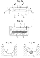
- Fig. 1a shows a transport channel 4 which is wetted by a liquid 3, on the surface 2 of which a micro-mechanical manufactured part 1 is placed.
- the predetermined path 5 of the micro-mechanical part 1 along which it is transported in the channel is shown in dotted lines.
- the channel is limited along the transport direction by side walls 6 and at the end of the transport path by channel end walls 8.
- the small micro-mechanical part 1 is maintained on the liquid surface 2 on account of the surface tension of the liquid 3.
- a stator 10 is provided in the channel base 9, the stator extending along the predetermined path 5 and being part of a synchronous linear motor.
- the small micro-mechanical part 1 is premagnitized and acts as the rotor of the synchronous linear motor.
- electromagnetic forces act on the small micro-mechanical part in order to move it along its transport path.
- the cross-section through the channel according to Fig. 1c shows how the liquid surface 2 is bent on account of the adhesion and cohesion forces between the liquid 3, the channel walls 6 and the surrounding atmosphere.
- a concave curvature of the liquid surface 2 is created in the transverse direction of the channel.
- the geometry of the liquid surface 2 shown in Fig. 1d is created.
- a concave curvature 2a is present at the channel side walls 6 and, after a turning point 2b, the surface then has a convex curvature 2e in the region of the micro-mechanical part 1.
- the micro-mechanical part is stabilized in the center of the channel. This ensues from the fact that the liquid surface 2 has a tendency to form a minimal surface.
- a path along the central line of the channel is predefined for the micro-mechanical part.
- the transport force acts to push the micro-mechanical part along this path.
- the shown part is an oblong manufactured part as, for example, a micro-surgical needle.
- Fig. 2a shows the cross-section of a wider channel than that shown in Fig. 1a to 1d.
- a concave curvature 2a of the liquid surface is only present in the area of the channel side walls 6, while a flat liquid surface 2d is present in the center of the channel.
- a planar micro-mechanical part 1 is placed on the channel cross-section according to Fig. 2a, the part being carried by the surface tension.
- a varying geometry of the liquid surface is created, from a concave curvature 2a via a turning point 2b to a convex curvature 2c.
- the planar micro-mechanical part adopts a stable position between the channel side walls 6.
- Fig. 3a shows a channel side wall 6 which, in connection with a vertical wall section, is angled outwardly in the lower region, a concave curvature 2a of the liquid surface forming at the edge.
- Fig. 3b shows a plate-like boundary member 12 which is arranged directly on the liquid surface 2. At the transition between the edge of the plate 12 and the free liquid surface, the liquid surface also bends concavely.
- a transport channel 13 is shown in which the channel width changes in the transport direction from a narrower channel section 13a to a wider channel section 13c.
- the narrower channel section 13a and the wider channel section 13c are connected by a channel section 13b which widens in the transport direction.
- a concave surface curvature according to Fig. 1c is created before placement of the micro-mechanical part.
- the curvature in the channel section 13a is greater than the curvature in the channel section 13c.
- a gradient 2f occurs along the widening channel section 13b. This grandient 2f is shown in Fig. 4b.
- a part placed on the liquid surface is accelerated along the gradient by the driving force of the incline and proceeds further along its predetermined path in the channel section 13c.
- the micro-mechanical part moves along its transport path in a stable manner between the channel side walls also in this case.
- a basin 14 filled with liquid 3 is shown, the liquid surface 2 of which is flat.
- a stator 10 is provided in the liquid of the basin, the stator being part of a synchronous linear motor.
- the premagnitized micro-mechanical part placed on the liquid surface acts as the rotor of the linear motor.
- the path for the micro-mechanical part is predefined on the liquid surface above the stator.
- the part placed on the liquid surface therefore follows the extension of the stator.
- the micro-mechanical part is not stabilized on the flat liquid surface in terms of its angular orientation, but it is held on account of the electromagnetic forces of the synchronous motor on the predetermined path and transported along this.
- Several synchronous linear motors can be arranged in a single liquid basin 14 and several predetermined paths 5 for a part can be connected with one another in this manner.
- Fig. 6a shows a basin 14 filled with liquid, boundary member 12 being arranged on the liquid surface. These members in the form of plates 12 are arranged at a distance from one another such that individual transport lanes 15 are created. Stators 10 of synchronous linear motors are respectively arranged to follow the transport lanes 15 beneath the predetermined paths 5 of parts, as can be seen in Fig. 6b. As Fig. 6b also shows, the geometry of the liquid surface in the transport lanes 15 are created respectively analogously to Fig. 1d (left-hand transport lane with a micro-mechanical part) and Fig. 1c (right-hand transport lane without a part).
- FIG. 7a to 7c An embodiment of an apparatus for positioning small micro-mechanical parts is shown in Fig. 7a to 7c.
- a channel section 16 with two channel end walls 8 corresponds in its proportions to the small micro-mechanical part 1 to be positioned.
- the dimensions of the liquid surface 2 in the channel are only slightly greater than the dimensions of the manufactured part 1.
- the micro-mechanical part positions itself in the liquid 3 on account of the geometry of the liquid surface which is created between the channel walls and the part on account of adhesion and cohesion forces as well as the gravitational force of the part.
- the part positions independently itself and lies in a stable position in which the surface of the liquid is minimized.
- Fig. 8 shows a further embodiment of an apparatus for positioning a micro-mechanical part.
- a channel section 17 is provided, an opening 18 with a conical inlet 19 being arranged at the one end of the channel section 17 in the channel end wall 8.
- the opening 18 is located at the level of the liquid surface 2 in the channel and lies in the extension of the predetermined transport path of the micro-mechanical part 1. Also in the extension of this transport path are, outside the channel, a stop 20 as well an electromagnet 21.
- a micro-mechanical part 1 of magnetic material placed on the liquid surface is attracted by the attraction force of the electromagnet 21 along a path 5 on the liquid surface, enters through the conical inlet 19 in the opening 18, is then drawn off the liquid surface and finally strikes the stop 20 against which it is held by the electromagnetic attraction force.
- this part passes the opening 18 at the end of the path 5, it has a defined spatial orientation and adopts a fixed position at the stop.
- an operational step can be carried out, for example the treatment of a micro-surgical needle with a laser.
- the micro-mechanical part not consist of magnetic material, but be premagnitized, it is also predefined which of its ends is attracted by the electromagnet.
- the inlet 19 simplifies the entry of the part from the liquid surface into the opening 18.
- Figs. 9a to 9c show an apparatus for transporting and positioning a micro-mechanical part.
- the apparatus includes a basin filled with liquid 3, a platform 22 and a synchronous linear motor.
- the platform 22 floats on the basin liquid on account of hydrostatic boyancy and/or surface tension.
- An opening to the surface of the liquid 3 in the basin is provided in the center of the platform 22. This opening serves as a positioning basin 23 for the small micro-mechanical part 1 to be transported and positioned.
- the small micro-mechanical part positions itself in a stable position in an analogous manner to that described with respect to Figs. 7a to 7c.
- the bending of the liquid surface between the edges of the positioning basin and the micro-mechanical part in the basin can be improved by appropriate geometrical shaping of the edges.
- Fig. 9b shows, the platform edges at the positioning basin are curved upwardly.
- the micro-mechanical part positions itself in a stable location within the positioning basin in which the liquid surface between the part and the edges of the positioning basin is minimized.
- the platform is provided with a magnetic part 24 which acts as the rotor of the synchronous linear motor.
- the associated stator 10 is placed in the liquid 3 of the basin and, on account of its longitudinal extension, defines the transport path 5 for the platform 22, and therefore also for the micro-mechanical part 1.
- the stator can equally be placed beneath the liquid 3, i.e.
- the part 1 to be conveyed can therfore also be of a non-magnetic material, as the platform adopts the function of the rotor of the synchronous linear motor.
- the part 1 is continuously positioned with respect to the platform 22 during transport.
- the micro-mechanical part can also, for example, adopt a tilted position.
- the platform 22 can naturally also have any other desired contour and means can be provided on the platform for the handling thereof.
- Fig. 10a shows a transport channel 25 as described, for example, in connection with Figs. 1a to 1d or Figs. 4a and 4b.
- a channel section 26 is cut out of the transport channel 25 and is, for example, rotatable about its vertical axis by means of a motor (not shown). The rotation of this channel section 26 ensues within semi-circular liquid-tight boundary walls 27 which prevent the liquid in the channel section 26 from flowing out of the channel section when the rotation occurs.
- the transport position of the channel section 26 is shown in which the section is aligned parallel to the transport channel 25 and a micro-mechanical part 1 on the liquid surface of the channel can thus be transported through the positioning apparatus along a predetermined path 5.
- micro-mechanical part 1 When the micro-mechanical part 1 is located in the channel section 26, this can be rotated, as shown in Fig. 10b, so that a closed positioning basin as shown in Figs. 7a to 7c is provided. As described above, the micro-mechanical part positions itself under the influence of gravitation within the channel section 26 bounded by the boundary walls 27. A manufacturing step can be carried out for the defined position of the part and the part can subsequently again be transported in the transport channel 25, following rotation of the channel section 26, back into the transport position.
- the transport force can, for example, be exerted on the part by means of a synchronous linear motor.
- micro-surgical needle 28 is positioned at the end of a channel 29 filled with liquid 3 which can also be arranged in a platform as described in connection with Figs. 9a to 9c.
- the liquid surface 2 serves as the reference level for the needle and the thread.
- the thread is led through the conical inlet opening 30 of the channel 29 and then aligned by means of respectively displaced aligning protrusions 31 such that the forward end of the thread is flush with the needle opening 32 of the prepositioned needle.
- the micro-surgical needle 28 is held in a defined position in a postioning basin 23 on the liquid surface and in meeting with the forward end of the micro-surgical thread 27 in the opening 32 of the needle, is pressed against a stop 34.
- the position of the micro-surgical needle is predefined by this stop.
- micro-surgical needle 28 As well as the micro-surgical thread 27 are both held on the surface of a liquid, they are not exposed to any mechanical loads during the threading step which normally occur in the case of commonly known mechanical gripping means, and damage or plastic deformation of the micro-mechanical needle is therefore avoided.
- the geometric shape of the channel with the inlet 30 and the aligning protrusions 31 as well as a positioning basin 33 ensure that the thread reliably enters the opening 32 of the needle.
- This apparatus considerably reduces the time required for threading the thread into the needle and subsequently making the connection thereof, as both steps take place at the same location and the thread is safely led to the opening. Thus, the quantity of rejects on account of damage or deformation of the needle is considerably reduced.
Landscapes
- Engineering & Computer Science (AREA)
- Physics & Mathematics (AREA)
- Power Engineering (AREA)
- Fluid Mechanics (AREA)
- Mechanical Engineering (AREA)
- Chemical & Material Sciences (AREA)
- Combustion & Propulsion (AREA)
- Electromagnetism (AREA)
- Micromachines (AREA)
- Manipulator (AREA)
- Non-Mechanical Conveyors (AREA)
Claims (23)
- Procédé pour positionner une petite pièce micromécanique oblongue (1) dans une orientation à obtenir lorsqu'elle est supportée par la tension superficielle à la surface d'un liquide stagnant, le procédé comprenant les étapes consistant à :i. définir l'orientation à obtenir par des éléments de délimitation (12) ;ii. choisir les matériaux respectifs pour les éléments de délimitation (12) formant une section de canal (16) d'une telle dimension que la pièce occupe une orientation stable dans celle-ci et que le liquide crée un ménisque concave vers le haut dans la surface du liquide adjacente aux éléments de délimitation (12) ; etiii. placer la petite pièce micromécanique sur la surface du liquide.
- Procédé selon la revendication 1, pour transporter de petites pièces micromécaniques, caractérisé en ce que, pour ladite petite pièce micromécanique (1) placée sur la surface (2) d'un liquide stagnant et tenue sur celle-ci à cause de la tension superficielle, un trajet prédéterminé (5) est formé, et en ce que la petite pièce micromécanique (1) est soumise à des forces externes, et en ce que la petite pièce micromécanique est transportée le long du trajet prédéterminé (5) sur la surface (2) du liquide (3) par des forces externes.
- Procédé selon la revendication 2, caractérisé en ce que la petite pièce micromécanique (1) est transportée le long du trajet prédéterminé (5) par des forces électromagnétiques.
- Procédé selon la revendication 2, caractérisé en ce que la petite pièce micromécanique (1) est transportée le long du trajet prédéterminé (5) par gravité.
- Procédé selon la revendication 2, caractérisé en ce que la petite pièce micromécanique (1) est transportée le long du trajet prédéterminé (5) par des forces aérodynamiques.
- Procédé selon la revendication 2, où la pièce (1) est un fil, et le procédé est efficace pour relier le fil à une aiguille qui est supportée elle-même par tension superficielle sur ladite surface du liquide.
- Procédé selon la revendication 1, incluant l'étape consistant à établir définitivement la position spatiale de la petite pièce micromécanique.
- Appareil pour maintenir une petite pièce micromécanique oblongue (1) dans une orientation voulue lorsque la pièce est supportée, en cours d'utilisation de l'appareil, par la tension superficielle à la surface d'un liquide stagnant, l'appareil comportant :des surfaces de délimitation de ménisque liquide (12) formant une section de canal (16) d'une telle dimension que la pièce occupe une orientation stable dans celle-ci qui définit l'orientation à obtenir de la pièce (1) par un ménisque concave vers le haut adjacent aux surfaces de délimitation.
- Appareil selon la revendication 8, incluant un canal (4) le long duquel la pièce (1) peut être transportée.
- Appareil selon la revendication 9, incluant des moyens pour soumettre dans un but précis la petite pièce micromécanique à des forces externes afin de solliciter la pièce le long du canal.
- Appareil selon la revendication 10, où les moyens de sollicitation définissent au moins un trajet de transport (5, 15) sur la surface du liquide.
- Appareil selon la revendication 11, où le moyen pour soumettre dans un but précis la petite pièce micromécanique à des forces externes comprend le stator (10) d'un moteur linéaire synchrone de telle sorte que le stator suit le trajet de transport (5, 15) dans son extension longitudinale.
- Appareil selon la revendication 12, caractérisé en ce que le stator (10) est agencé en dessous du trajet de transport (5, 15) dans la base (9) du canal.
- Appareil selon la revendication 10 ou 11, caractérisé en ce que le moyen pour soumettre dans un but précis la petite pièce micromécanique (1) à des forces externes comporte un générateur de flux d'air efficace dans la direction de transport de la petite pièce micromécanique.
- Appareil selon l'une des revendications 8 à 14, caractérisé en ce que la largeur du canal augmente dans la direction de transport au moins dans une section de canal (13b) le long du trajet prédéterminé.
- Appareil selon la revendication 8, pour orienter de petites pièces micromécaniques oblongues, caractérisé en ce qu'une section de canal (16) est prévue qui est limitée dans sa dimension longitudinale par deux parois d'extrémité de canal (8).
- Appareil selon la revendication 16 et caractérisé par :- la paroi d'extrémité de canal à l'extrémité du canal (17) ferme le canal dans la direction de transport,- une ouverture (18) dans la paroi d'extrémité du canal (8) approximativement au niveau de la surface du liquide (2) et dans le prolongement du trajet prédéterminé (5) de la petite pièce micromécanique (1),- un électroaimant ou aimant permanent (21) agencé à l'extérieur du canal à la distance derrière l'ouverture (18) de la paroi d'extrémité de canal et- une butée (20) pour la petite pièce micromécanique entre l'ouverture (18) et l'électroaimant ou l'aimant permanent (21).
- Appareil selon la revendication 17, caractérisé en ce que l'ouverture (18) a une entrée (19) au côté de la paroi d'extrémité de canal (8) orientée vers l'intérieur du canal qui s'élargit dans la direction vers le canal (17).
- Appareil selon la revendication 8 ou 9, incluant :- un bassin rempli de liquide (3),- une plate-forme (22) qui, en cours d'utilisation, flotte sur la surface du liquide (2) dans le bassin à cause de la flottabilité hydrostatique et/ou la tension superficielle et- un moyen pour soumettre la plate-forme (22) à des forces externes,- où un bassin de positionnement (23) est formé dans la plate-forme pour recevoir la petite pièce micromécanique (1), le bassin de positionnement délimitant une surface du liquide de telle sorte qu'avant la mise en place de la petite pièce micromécanique et en raison des forces d'adhésion et de cohésion entre le liquide, les bords du bassin de positionnement et le milieu au-dessus du liquide, une surface de liquide de courbure concave est formée au moins aux bords du bassin de positionnement (23).
- Appareil selon la revendication 19, caractérisé en ce que le moyen pour soumettre la plate-forme (22) à des forces externes inclut un moteur linéaire synchrone,- dont le stator (10) définit le trajet (5) de la plate-forme sur la surface (2) du liquide (3) par son extension longitudinale et est agencé pour être adjacent audit trajet à obtenir (5), et- dont le rotor est constitué par au moins une pièce magnétique (24) de la plate-forme (22).
- Appareil selon la revendication 19 ou 20, caractérisé en ce que le bassin de positionnement (23) dans la plate-forme (22) délimite une surface partielle de la surface du liquide du bassin sur laquelle flotte la plate-forme.
- Appareil selon la revendication 19 ou 20, caractérisé en ce que le bassin de positionnement (23) est réalisé dans la plate-forme (22) comme un bain fermé mouillé avec un liquide.
- Procédé selon la revendication 7, caractérisé en ce qu'un élément de délimitation est agencé dans un bassin rempli de liquide sur la surface du liquide et délimite une zone de la surface du liquide où- les proportions de la zone correspondent sensiblement à la petite pièce micromécanique à positionner et- les dimensions géométriques de la zone sont seulement légèrement plus grandes que celles de la petite pièce micromécanique.
Applications Claiming Priority (2)
| Application Number | Priority Date | Filing Date | Title |
|---|---|---|---|
| DE4307730 | 1993-03-11 | ||
| DE4307730A DE4307730A1 (de) | 1993-03-11 | 1993-03-11 | Verfahren und Vorrichtung zum Transport und zum Positionieren mikromechanischer Teilchen |
Publications (2)
| Publication Number | Publication Date |
|---|---|
| EP0619253A1 EP0619253A1 (fr) | 1994-10-12 |
| EP0619253B1 true EP0619253B1 (fr) | 1997-11-05 |
Family
ID=6482532
Family Applications (1)
| Application Number | Title | Priority Date | Filing Date |
|---|---|---|---|
| EP93112502A Expired - Lifetime EP0619253B1 (fr) | 1993-03-11 | 1993-08-04 | Procédé et appareil pour positionner et tranporter des pièces micromécaniques |
Country Status (4)
| Country | Link |
|---|---|
| US (1) | US5413203A (fr) |
| EP (1) | EP0619253B1 (fr) |
| CA (1) | CA2113285C (fr) |
| DE (2) | DE4307730A1 (fr) |
Families Citing this family (4)
| Publication number | Priority date | Publication date | Assignee | Title |
|---|---|---|---|---|
| DE10244867B4 (de) * | 2002-09-23 | 2004-12-30 | Technische Universität Berlin | Einrichtung zum Positionieren eines Körpers |
| US6848566B2 (en) * | 2003-06-30 | 2005-02-01 | The Procter & Gamble Company | Continuously adjustable apparatus for repositioning discrete articles |
| DE102006008315B4 (de) * | 2006-02-18 | 2007-12-06 | Hahn-Meitner-Institut Berlin Gmbh | Miniaturisierte Transportsysteme aus einem Formgedächtnis-Polymer und Verfahren zur Herstellung |
| EP4631909A1 (fr) | 2024-04-11 | 2025-10-15 | Technische Universität Ilmenau | Dispositif et procédé de transport de composants micromécaniques |
Family Cites Families (4)
| Publication number | Priority date | Publication date | Assignee | Title |
|---|---|---|---|---|
| AT115733B (de) * | 1928-07-28 | 1930-01-10 | Carl Ing Rein | Einrichtung zur Fortbewegung von Arbeitsstücken im Fließbetriebe. |
| DE1481389A1 (de) * | 1966-01-19 | 1969-04-03 | Vanfrido Olivotto | Foerderer fuer Tafeln u.dgl. mittels eines Flud |
| JPS6181324A (ja) * | 1984-09-26 | 1986-04-24 | Shinko Electric Co Ltd | 搬送装置 |
| US4591392A (en) * | 1984-12-13 | 1986-05-27 | At&T Bell Laboratories | Forming an ordered array for visual inspection |
-
1993
- 1993-03-11 DE DE4307730A patent/DE4307730A1/de not_active Withdrawn
- 1993-08-04 DE DE69315057T patent/DE69315057T2/de not_active Expired - Lifetime
- 1993-08-04 EP EP93112502A patent/EP0619253B1/fr not_active Expired - Lifetime
- 1993-10-20 US US08/140,355 patent/US5413203A/en not_active Expired - Lifetime
-
1994
- 1994-01-12 CA CA002113285A patent/CA2113285C/fr not_active Expired - Lifetime
Also Published As
| Publication number | Publication date |
|---|---|
| DE4307730A1 (de) | 1994-09-15 |
| DE69315057D1 (de) | 1997-12-11 |
| CA2113285A1 (fr) | 1994-09-12 |
| US5413203A (en) | 1995-05-09 |
| CA2113285C (fr) | 2006-07-11 |
| EP0619253A1 (fr) | 1994-10-12 |
| DE69315057T2 (de) | 1998-04-02 |
Similar Documents
| Publication | Publication Date | Title |
|---|---|---|
| US5246218A (en) | Apparatus for securing an automatically loaded wafer cassette on a wafer processing equipment | |
| EP3349015B1 (fr) | Système de distribution d'échantillon de laboratoire et procédé correspondant de fonctionnement | |
| US7811854B2 (en) | Assembling stacked substrates that can form 3-D structures | |
| EP0619253B1 (fr) | Procédé et appareil pour positionner et tranporter des pièces micromécaniques | |
| JP2000502477A (ja) | ワイヤ導体を接触させるための方法及び装置 | |
| US7946174B2 (en) | Decelerometer formed by levitating a substrate into equilibrium | |
| KR19990082483A (ko) | 와이어도체 접속 방법 및 장치 | |
| CA2544246C (fr) | Methode et appareil de transport et de positionnement de pieces micromecaniques | |
| DE102017222477A1 (de) | Laserbearbeitungsvorrichtung | |
| US4634043A (en) | Engaging second articles to engaged first articles | |
| EP0109991B1 (fr) | Chute d'alimentation à gravité | |
| US7812336B2 (en) | Levitating substrate being charged by a non-volatile device and powered by a charged capacitor or bonding wire | |
| US6396022B1 (en) | Method and device for replacing pipe electrode for small-hole electric discharge machining and electrode magazine | |
| EP0090503A2 (fr) | Appareil et procédé pour encapsuler un dispositif semi-conducteur | |
| DE102004026534B4 (de) | Halbleiter-Montageeinrichtung | |
| US20050092782A1 (en) | Dispenser nozzle, dispenser incorporating the dispenser nozzle, method for dispensing a viscous substance | |
| US8531848B2 (en) | Coulomb island and Faraday shield used to create adjustable Coulomb forces | |
| EP2905221A1 (fr) | Procédé et appareil de fabrication d'une coque pour un avion ou un engin spatial | |
| US7863651B2 (en) | Using multiple coulomb islands to reduce voltage stress | |
| EP0905064A1 (fr) | Transporteur d'articles | |
| US6170640B1 (en) | Carrying system and carrying method | |
| US7086145B2 (en) | Magazine, assembly device for microcomponents | |
| DE2855706C2 (fr) | ||
| CA1301558C (fr) | Transport controle de corps de boites metalliques dans une ligne de boites | |
| Zenger et al. | Automatic handling of parts for robot assembly |
Legal Events
| Date | Code | Title | Description |
|---|---|---|---|
| PUAI | Public reference made under article 153(3) epc to a published international application that has entered the european phase |
Free format text: ORIGINAL CODE: 0009012 |
|
| AK | Designated contracting states |
Kind code of ref document: A1 Designated state(s): DE ES FR GB IT |
|
| 17P | Request for examination filed |
Effective date: 19950216 |
|
| 17Q | First examination report despatched |
Effective date: 19960319 |
|
| GRAG | Despatch of communication of intention to grant |
Free format text: ORIGINAL CODE: EPIDOS AGRA |
|
| GRAH | Despatch of communication of intention to grant a patent |
Free format text: ORIGINAL CODE: EPIDOS IGRA |
|
| GRAH | Despatch of communication of intention to grant a patent |
Free format text: ORIGINAL CODE: EPIDOS IGRA |
|
| GRAA | (expected) grant |
Free format text: ORIGINAL CODE: 0009210 |
|
| AK | Designated contracting states |
Kind code of ref document: B1 Designated state(s): DE ES FR GB IT |
|
| PG25 | Lapsed in a contracting state [announced via postgrant information from national office to epo] |
Ref country code: IT Free format text: LAPSE BECAUSE OF FAILURE TO SUBMIT A TRANSLATION OF THE DESCRIPTION OR TO PAY THE FEE WITHIN THE PRE;WARNING: LAPSES OF ITALIAN PATENTS WITH EFFECTIVE DATE BEFORE 2007 MAY HAVE OCCURRED AT ANY TIME BEFORE 2007. THE CORRECT EFFECTIVE DATE MAY BE DIFFERENT FROM THE ONE RECORDED.SCRIBED TIME-LIMIT Effective date: 19971105 Ref country code: ES Free format text: THE PATENT HAS BEEN ANNULLED BY A DECISION OF A NATIONAL AUTHORITY Effective date: 19971105 |
|
| REF | Corresponds to: |
Ref document number: 69315057 Country of ref document: DE Date of ref document: 19971211 |
|
| ET | Fr: translation filed | ||
| PLBE | No opposition filed within time limit |
Free format text: ORIGINAL CODE: 0009261 |
|
| 26N | No opposition filed | ||
| REG | Reference to a national code |
Ref country code: GB Ref legal event code: IF02 |
|
| PGFP | Annual fee paid to national office [announced via postgrant information from national office to epo] |
Ref country code: GB Payment date: 20120828 Year of fee payment: 20 |
|
| PGFP | Annual fee paid to national office [announced via postgrant information from national office to epo] |
Ref country code: FR Payment date: 20120830 Year of fee payment: 20 Ref country code: DE Payment date: 20120829 Year of fee payment: 20 |
|
| REG | Reference to a national code |
Ref country code: DE Ref legal event code: R071 Ref document number: 69315057 Country of ref document: DE |
|
| REG | Reference to a national code |
Ref country code: GB Ref legal event code: PE20 Expiry date: 20130803 |
|
| PG25 | Lapsed in a contracting state [announced via postgrant information from national office to epo] |
Ref country code: DE Free format text: LAPSE BECAUSE OF EXPIRATION OF PROTECTION Effective date: 20130806 |
|
| PG25 | Lapsed in a contracting state [announced via postgrant information from national office to epo] |
Ref country code: GB Free format text: LAPSE BECAUSE OF EXPIRATION OF PROTECTION Effective date: 20130803 |