EP2905221A1 - Procédé et appareil de fabrication d'une coque pour un avion ou un engin spatial - Google Patents
Procédé et appareil de fabrication d'une coque pour un avion ou un engin spatial Download PDFInfo
- Publication number
- EP2905221A1 EP2905221A1 EP14154486.6A EP14154486A EP2905221A1 EP 2905221 A1 EP2905221 A1 EP 2905221A1 EP 14154486 A EP14154486 A EP 14154486A EP 2905221 A1 EP2905221 A1 EP 2905221A1
- Authority
- EP
- European Patent Office
- Prior art keywords
- stringer
- skin
- mousehole
- frame
- skin panel
- Prior art date
- Legal status (The legal status is an assumption and is not a legal conclusion. Google has not performed a legal analysis and makes no representation as to the accuracy of the status listed.)
- Granted
Links
Images



Classifications
-
- B—PERFORMING OPERATIONS; TRANSPORTING
- B64—AIRCRAFT; AVIATION; COSMONAUTICS
- B64C—AEROPLANES; HELICOPTERS
- B64C1/00—Fuselages; Constructional features common to fuselages, wings, stabilising surfaces or the like
- B64C1/06—Frames; Stringers; Longerons ; Fuselage sections
- B64C1/12—Construction or attachment of skin panels
-
- B—PERFORMING OPERATIONS; TRANSPORTING
- B64—AIRCRAFT; AVIATION; COSMONAUTICS
- B64C—AEROPLANES; HELICOPTERS
- B64C3/00—Wings
- B64C3/26—Construction, shape, or attachment of separate skins, e.g. panels
-
- B—PERFORMING OPERATIONS; TRANSPORTING
- B64—AIRCRAFT; AVIATION; COSMONAUTICS
- B64F—GROUND OR AIRCRAFT-CARRIER-DECK INSTALLATIONS SPECIALLY ADAPTED FOR USE IN CONNECTION WITH AIRCRAFT; DESIGNING, MANUFACTURING, ASSEMBLING, CLEANING, MAINTAINING OR REPAIRING AIRCRAFT, NOT OTHERWISE PROVIDED FOR; HANDLING, TRANSPORTING, TESTING OR INSPECTING AIRCRAFT COMPONENTS, NOT OTHERWISE PROVIDED FOR
- B64F5/00—Designing, manufacturing, assembling, cleaning, maintaining or repairing aircraft, not otherwise provided for; Handling, transporting, testing or inspecting aircraft components, not otherwise provided for
- B64F5/10—Manufacturing or assembling aircraft, e.g. jigs therefor
-
- B—PERFORMING OPERATIONS; TRANSPORTING
- B64—AIRCRAFT; AVIATION; COSMONAUTICS
- B64G—COSMONAUTICS; VEHICLES OR EQUIPMENT THEREFOR
- B64G1/00—Cosmonautic vehicles
- B64G1/22—Parts of, or equipment specially adapted for fitting in or to, cosmonautic vehicles
-
- B—PERFORMING OPERATIONS; TRANSPORTING
- B64—AIRCRAFT; AVIATION; COSMONAUTICS
- B64U—UNMANNED AERIAL VEHICLES [UAV]; EQUIPMENT THEREFOR
- B64U20/00—Constructional aspects of UAVs
- B64U20/70—Constructional aspects of the UAV body
-
- B—PERFORMING OPERATIONS; TRANSPORTING
- B23—MACHINE TOOLS; METAL-WORKING NOT OTHERWISE PROVIDED FOR
- B23P—METAL-WORKING NOT OTHERWISE PROVIDED FOR; COMBINED OPERATIONS; UNIVERSAL MACHINE TOOLS
- B23P2700/00—Indexing scheme relating to the articles being treated, e.g. manufactured, repaired, assembled, connected or other operations covered in the subgroups
- B23P2700/01—Aircraft parts
-
- Y—GENERAL TAGGING OF NEW TECHNOLOGICAL DEVELOPMENTS; GENERAL TAGGING OF CROSS-SECTIONAL TECHNOLOGIES SPANNING OVER SEVERAL SECTIONS OF THE IPC; TECHNICAL SUBJECTS COVERED BY FORMER USPC CROSS-REFERENCE ART COLLECTIONS [XRACs] AND DIGESTS
- Y10—TECHNICAL SUBJECTS COVERED BY FORMER USPC
- Y10T—TECHNICAL SUBJECTS COVERED BY FORMER US CLASSIFICATION
- Y10T29/00—Metal working
- Y10T29/49—Method of mechanical manufacture
- Y10T29/49616—Structural member making
- Y10T29/49622—Vehicular structural member making
-
- Y—GENERAL TAGGING OF NEW TECHNOLOGICAL DEVELOPMENTS; GENERAL TAGGING OF CROSS-SECTIONAL TECHNOLOGIES SPANNING OVER SEVERAL SECTIONS OF THE IPC; TECHNICAL SUBJECTS COVERED BY FORMER USPC CROSS-REFERENCE ART COLLECTIONS [XRACs] AND DIGESTS
- Y10—TECHNICAL SUBJECTS COVERED BY FORMER USPC
- Y10T—TECHNICAL SUBJECTS COVERED BY FORMER US CLASSIFICATION
- Y10T29/00—Metal working
- Y10T29/53—Means to assemble or disassemble
- Y10T29/53961—Means to assemble or disassemble with work-holder for assembly
- Y10T29/5397—Means to assemble or disassemble with work-holder for assembly and assembling press [e.g., truss assembling means, etc.]
Definitions
- the present invention relates to a method for manufacturing a shell component for an aircraft or spacecraft. Furthermore, the invention relates to an apparatus for manufacturing such a component.
- integral frames include an integrated foot section with contact surfaces for contacting the aircraft skin between the stringers, such that separate clips and labour-intensive operations for connecting clips and frames are unnecessary.
- the contact surfaces of the foot section are separated by so-called mouseholes, which are holes or recesses formed in the foot section at each position where a stringer crosses the frame.
- mouseholes are holes or recesses formed in the foot section at each position where a stringer crosses the frame.
- this object is attained by a manufacturing method with the features of claim 1 and a manufacturing apparatus with the features of claim 14.
- a skin panel which includes a skin of the aircraft or spacecraft and first and second stringers stiffening the skin, is positioned opposite a frame having first and second mouseholes for receiving the first and second stringers, the skin panel is elastically bent, the first stringer is inserted into the first mousehole, and the elastic bend is released to insert the second stringer into the second mousehole.
- the bending of the skin panel enables the first stringer to be introduced into the first mousehole without requiring the second stringer to be introduced into the second mousehole at the same time, while the release of the bending of the skin panel enables the second stringer to be introduced into the second mousehole without requiring the first stringer to be introduced into the first mousehole at the same time. Therefore, it becomes possible to design the first and second mouseholes with small sizes, to prevent local skin bulging, without requiring a division of the frame into short segments e.g. between the first and second mousehole. This enables to achieve a favourable strength-to-weight ratio of the shell component while simplifying the manufacturing process such that manufacturing cost can be reduced because an assembly involving connection of several short frame segments is unnecessary. As a further advantage, longer frame segments ensure a high precision of the outer contour of the aircraft or spacecraft.
- the inventive method is suitable for automation because the bending, inserting and releasing operations can conveniently be performed from the outside without being constrained by shortage of space on the interior side of the shell component. Therefore, the steps of the method can be performed by e.g. a robot or other apparatus that can conveniently positioned without size considerations.
- the inventive manufacturing apparatus comprises a positioning unit for positioning a skin panel, which includes a skin of the aircraft or spacecraft and first and second stringers stiffening the skin, opposite a frame having first and second mouseholes for receiving the first and second stringers, a bending unit for elastically bending the skin panel, an inserting unit for inserting the first stringer into the first mousehole, and a control unit, which controls the bending unit to release the elastic bend in order to insert the second stringer into the second mousehole.
- a positioning unit for positioning a skin panel, which includes a skin of the aircraft or spacecraft and first and second stringers stiffening the skin, opposite a frame having first and second mouseholes for receiving the first and second stringers, a bending unit for elastically bending the skin panel, an inserting unit for inserting the first stringer into the first mousehole, and a control unit, which controls the bending unit to release the elastic bend in order to insert the second stringer into the second mousehole.
- the frame comprises a curved contact surface for contacting the skin, the method further comprising providing the skin with a curvature to fit the contact surface.
- the skin may be prepared by imparting the curvature to a flat metal sheet by rolling, or may be manufactured e.g. from fibre-reinforced plastic comprising the curvature from the beginning. Because of this, the skin comes to precisely conform to the contact surface after simply releasing the elastic bend.
- an asymmetric outline of the second mousehole includes, on the side facing the first mousehole, a perpendicular outline portion extending substantially perpendicular to the contact surface.
- the second mousehole can be made particularly small with a profile that becomes narrower toward the contact surface.
- an asymmetric profile is enabled to be chosen for the second stringer wherein a stringer web extends substantially perpendicularly from the skin on the side of the second stringer that faces the first stringer, and a flange of the second stringer extends from the stringer web to the side of the second stringer that faces away from the first stringer.
- the skin panel further includes a first reverse stringer symmetric to the first stringer with respect to a symmetry plane of the skin panel, the step of inserting the first stringer involving simultaneously inserting the first reverse stringer into a first reverse mousehole of the frame.
- the method can be performed particularly efficiently by choosing mirror-symmetric profiles for the stringers and mouseholes that enable simultaneous insertion, e.g. at the top centre location of the aircraft.
- the skin panel further includes a second reverse stringer on a side of the first stringer (111) facing away from the second stringer, while the method further comprises a step of inserting the second reverse stringer into a second reverse mousehole of the frame, after the step of inserting the first stringer.
- the first stringer is located on the skin panel between the second stringer and the second reverse stringer, this enables to start inserting stringers of the skin panel into corresponding mouseholes from a stringer that is located amidst other stringers, including e.g. a stringer close to a centre of the skin panel.
- the first stringer from among the stringers of the skin panel in such a way that elastic deformations occurring during the performance of the method, assembly tolerances etc. are distributed as evenly as possible over the skin panel, thereby enabling the frame to comprise a particularly long frame segment.
- the second reverse stringer is symmetric to the second stringer with respect to a symmetry plane of the skin panel. In this way, a single skin panel is enabled to be conveniently attached to a large, symmetric frame portion such as at the top centre location of the aircraft.
- the step of elastically bending the skin panel comprises introducing an outward bend directed away from the frame.
- the skin panel can be moved away from the frame in a location other than the first mousehole, thus enabling the first stringer to be introduced into the first mousehole in cases where this introduction would otherwise lead to a collision between the skin panel and the frame in said location.
- the outward bend is introduced into the skin between the first stringer and the second stringer, thus enabling the second stringer to be moved away from the frame in a case where it would otherwise collide with the frame. More preferably, the position where the outward bend is introduced is closer to the first stringer. This has the effect that the second stringer can be moved by a large extent from the frame with only a small bend, e.g. within the elastic limit.
- the step of elastically bending the skin panel comprises introducing an inward bend directed toward the frame.
- This enables the second stringer to be introduced into the second mousehole in cases where its orientation would otherwise not allow the introduction.
- the second mousehole can be given a particularly narrow shape, leading to a further improved strength-to-weight ratio of the shell component.
- the inward bend is introduced into the skin between the first stringer and the second stringer in a position closer to the second stringer.
- the second stringer can be tilted into the required orientation without bringing it substantially closer to the frame, e.g. in cases where this would otherwise let the second stringer collide with the frame outside the second mousehole.
- the second mousehole can be given an even narrower shape.
- the step of elastically bending the skin panel is performed at least partly before the step of inserting the first stringer into the first mousehole.
- the step of elastically bending the skin panel is performed at least partly simultaneously with the step of inserting the first stringer into the first mousehole. This enables the method to be performed particularly quickly.
- the method further comprises a step of arranging the frame.
- the frame is arranged in a tool, which fixes it and ensures the outer contour of the aircraft.
- the step of arranging the frame is performed before the step of positioning the skin panel, for greater precision.
- a plurality of frames having respective first and second mouseholes for receiving the first and second stringers is arranged, the skin panel is positioned opposite each frame, the first stringer is inserted into each first mousehole, and the elastic bend is released to insert the second stringer into each second mousehole. In this way, larger shell components extending over more than one frame can be efficiently manufactured.
- the positioning unit comprises a plurality of suction cups for holding the skin panel, the bending unit including a drive for independently moving the suction cups to perform the elastic bending of the skin panel. This enables the skin panel to be handled gently regardless of its material.
- Figure 1 shows, in a schematic planar side view, a manufacturing apparatus 200 for manufacturing a shell component for an aircraft or spacecraft by joining a skin panel 102, which is exemplarily shown to consist of a convexly curved skin 104 portion of the aircraft or spacecraft and a plurality of stringers 110-114, 160-164 affixed to an inner surface 105 thereof, to an integral frame 106, which has a correspondingly convexly curved contact surface 108 for contacting the inner surface 105 of the skin 104 and a plurality of mouseholes 120-124, 170-174, formed in the contact surface 108 in the shape of mouseholes, for respectively receiving each of the stringers 110-114, 160-164 therein.
- a skin panel 102 which is exemplarily shown to consist of a convexly curved skin 104 portion of the aircraft or spacecraft and a plurality of stringers 110-114, 160-164 affixed to an inner surface 105 thereof, to an integral frame 106, which has a
- the frame 106 is not limited to any particular type of cross-section and may be configured e.g. as a Z-, F-, E-, ⁇ - or J-frame. Both the skin panel 102 and the frame 106 are shown to be mirror-symmetric with respect to a symmetry plane 156, which in the present example corresponds to the main symmetry plane of an aircraft for which the shell component is intended to be manufactured.
- the frame 106 is shown in a state where it has been mounted on a frame support tool 201 comprised by the manufacturing apparatus 200 in order to rigidly support the frame 106 in a predetermined position.
- the frame 106 is shown oriented parallel to the drawing plane with its contact surface 108 pointing upward and the symmetry plane 156 oriented perpendicular to the drawing plane.
- the manufacturing apparatus 200 further comprises a positioning unit 203 for positioning the skin panel 102 opposite the contact surface 108 of the frame 106.
- the positioning unit 203 is realised as a suspension beam that suspends the skin panel 102 from e.g. a ceiling (not shown) above the frame support tool 201 in an aligned fashion such that each stringer 110-114, 160-164 is positioned above a corresponding one of the mouseholes 120-124, 170-174.
- the manufacturing apparatus 200 comprises an inserting unit 202 for inserting at least one of the stringers 110-114, 160-164 into the corresponding one of the mouseholes 120-124, 170-174 when the skin panel 102 has been positioned by the positioning unit 203.
- the inserting unit 202 is a drive that lowers the positioning unit 203 with the skin panel 102 toward the frame 106 in order to introduce the at least one of the stringers into the corresponding mousehole.
- the manufacturing apparatus 200 furthermore comprises a bending unit 204 for elastically bending the skin panel 102 at predetermined locations.
- the bending unit 204 includes a plurality of suction cups 211 for attaching to the outer surface 115 of the skin 104 in predetermined locations as well as a plurality of drives 205 for positioning the suction cups 211 relative to each other in order to introduce bending forces into the skin 104.
- Figure 1 for ease of representation schematically shows two drives 205 controlling three suction cups 211 each.
- the bending unit 204 is assumed to be configured with as many drives 205 and suction cups 211 as needed to elastically bend the skin panel 102 at the predetermined locations.
- the bending unit 204 may comprise one drive 205 and three suction cups 211 controlled by the drive 205.
- the bending unit 204 furthermore serves to attach the skin panel 102 to the positioning unit 203.
- the manufacturing apparatus 200 comprises a control unit 208, which is configured to control the overall operation of the manufacturing apparatus 200.
- the control unit 208 is configured to control the inserting unit 202 such that the at least one of the stringers 110-114, 160-164 is inserted into the corresponding one of the mouseholes 120-124, 170-174.
- the control unit 208 is configured to control the drives 205 and suction cups 211 of the bending unit 204 to cause an elastic bend of the skin panel 102 in at least one predetermined location, and also to release the elastic bend in order to insert at least a second one of the stringers 110-114, 160-164 into a corresponding second one of the mouseholes 120-124, 170-174.
- Figure 1 depicts the manufacturing apparatus 200 in a state where it has, by using its positioning unit 203 under the control of its control unit 208, positioned the skin panel 102 at a height H above the frame 106, the skin panel 102 being aligned with respect to the frame 106 in such a way that all stringer 110-114, 160-164 are located exactly above the respective corresponding one of the mouseholes 120-124, 170-174.
- the height H is set to a predetermined value such as 160 mm.
- Figure 1 illustrates not only a manufacturing apparatus according to an embodiment but also Step 1 of a manufacturing method of a shell component for an aircraft or spacecraft according to an embodiment of the invention. Further steps of the method will in the following be explained by making reference to Figures 2 to 9 .
- the manufacturing apparatus 200 although present, has been omitted from Figures 2 to 9 .
- both the frame 106 and the skin panel 102 are mirror-symmetric with respect to the symmetry plane 156, only one half of the frame 106 and the skin panel 102 is depicted in Figures 2 to 9 , with the assumption that the respective method steps are performed symmetrically in both halves.
- each stringer 110-114, 160-164 comprises an asymmetric profile resembling the shape of a walking cane or the capital letter "J".
- the profile of the stringers 110-114, 160-164 is oriented such that a perpendicular stringer web, which is substantially perpendicular to the skin 104, of the "J"-profile faces toward the symmetry plane 156.
- the shape of the profile of one or more of the stringers 110-114, 160-164 may differ, e.g. resemble the shape of the capital letter "Z” or the Greek capital letter "D".
- the mouseholes 120-124, 170-174 each comprise an asymmetric outline with a perpendicular outline portion 152 extending substantially perpendicular to the contact surface 108 on the side facing toward the symmetry plane 156.
- the outlines of the mouseholes 120-124, 170-174 have narrowing outline portions 154 that are tilted with respect to the contact surface 108 in such a way that the mouseholes 120-124, 170-174 become narrower in the vicinity of the contact surface 108.
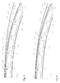
- FIG 2 illustrates Step 2 of the manufacturing method that follows after the step depicted in Figure 1 .
- the skin 104 of the skin panel 102 is elastically bent in four bending locations 300-303 by e.g. 1o each into the direction away from the contact surface 108 of the frame 106.
- the bending locations 300-301 are located closely behind the first four stringers 110-113 as seen from the symmetry plane 156.
- the bending locations 300-303 are marked in Figure 2 by full-circle markers, which throughout the Figures signify that an elastic bend away from the contact surface (as seen from the symmetry plane 156) has been newly introduced in the method step depicted by the respective figure.
- Step 3 is illustrated in Figure 3 .
- the elastic bends 300-304 introduced in the previous method step are retained.
- elastic bends away from the contact surface (as seen from the symmetry plane 156) that are retained from previous method steps are indicated by open circle markers.
- a further elastic bend 309 of e.g. 1o directed away from the frame 106 is introduced between the stringer 110 closest to the symmetry plane 156 (to be called zeroth stringer 110 below) and the neighbouring first stringer 111 in a bend location distanced from the zeroth stringer 110 by about one quarter of the distance between the zeroth and first stringers 110, 111.
- the height H of the skin panel 102 above the frame 106 is reduced to e.g. 20 mm by action of the inserting unit as controlled by the control unit.
- the zeroth stringer 110 is inserted partially into the corresponding zeroth mousehole 120, and the first stringer 111, which has been lifted relative to the zeroth stringer 110 by the two elastic bends 300, 309 between the zeroth and first stringers 110, 111, is introduced to a lesser degree into the corresponding first mousehole 121.
- the zeroth reverse stringer 160 is partially inserted into the corresponding zeroth reverse mousehole 170 simultaneously with the zeroth stringer 110 being inserted partially into the corresponding zeroth mousehole 120, and the and the first reverse stringer 161 is introduced to into the corresponding first reverse mousehole 171 at the same time and to the same degree as the first stringer 111 is introduced into the corresponding first mousehole 121.
- the second stringer 112 due to having been lifted relative to the zeroth stringer 110 by seven elastic bends 300, 301, 305-309 away from the frame 106, is prevented from colliding with the contact surface 108.
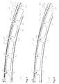
- Figure 4 illustrates subsequent Step 4 of the method.
- the height H is further reduced to e.g. 15 mm, before the outward elastic bend 308 introduced in the previous step is released and replaced by an inward elastic bend 308' by e.g. 1o, i.e. an elastic bend that, as seen from the symmetry plane 156, elastically bends the skin 104 by this amount toward the frame 106.
- This rotates the second stringer 112, which in the previous step, based on the exemplary bending amounts given above, had been rotated by an exemplary total of 7o against the orientation of the corresponding second mousehole 122, into an orientation that deviates only by an exemplary total of 5o from the orientation of the second mousehole 122.
- the inward elastic bend 308' is marked in Figure 4 as newly introduced by a full-triangle marker, and in the following figures as previously introduced by an open-triangle marker.
- Step 5 the inserting unit under the control of the control unit lowers the skin panel 102 to further reduce the height H at the symmetry plane 156, above the aircraft centre, to e.g. 4 mm. This results in a farther insertion of the zeroth and first stringers 110, 111 in their respective mouseholes 120, 121 while the second stringer 112 begins its insertion into the second mousehole 122.
- Step 6 as illustrated by Figure 6 , all elastic bends 300, 309 between the zeroth and first stringers 110, 111 are released, such that the skin panel 102 assumes its original shape in the interval between the symmetry plane 156 and the first stringer 111. This release results in a farther insertion of the first stringer 111 into the first mousehole 121 and the second stringer 112 into the second mousehole 122.
- Step 7 as illustrated by Figure 7 , a new downward elastic bend 304 by e.g. 1o is introduced at a location immediately preceding the fourth stringer 114, as seen from the symmetry plane 156, in order to prevent a collision of the fourth stringer 114 with the frame 106. All other elastic bends 301, 305, 302 are released, except the upward and downward elastic bends 307, 308', which immediately precede the second stringer 112. The release introduces the second stringer 112 farther into the second mousehole 122. Because the remaining elastic bends 307, 308' are of opposite direction, the angular orientation of the second stringer 112 now exactly agrees with the orientation of the second mousehole 122.
- Step 8 as illustrated by Figure 8 , the height H at the symmetry plane 156 is reduced to 0 mm, thus bringing the zeroth and first stringers 110, 111 into their final positions with respect to the frame 106.
- Step 9 as illustrated by Figure 9 , the last three remaining elastic bends 304, 307, 308' are released, thus bringing all stringers 110-114 into their respective final positions with respect to the frame 106.
- the skin panel 102 is affixed by rivets 158 to the frame 106. Although only three rivets 158 are shown as an example, the affixation is performed along the entire length of the skin panel 102 in contact with the contact surface 108.
- insertion of stringers 110-114, 160-164 into their corresponding mouseholes 120-124, 170-124 begins from the location of the symmetry plane 156 of the frame 106, such that the zeroth stringer 110 and the zeroth reverse stringer 160, which are closest to the symmetry plane 106 are inserted first.
- different locations may be chosen from where to begin the insertion of stringers.
Landscapes
- Engineering & Computer Science (AREA)
- Aviation & Aerospace Engineering (AREA)
- Mechanical Engineering (AREA)
- Remote Sensing (AREA)
- Manufacturing & Machinery (AREA)
- Transportation (AREA)
- Moulding By Coating Moulds (AREA)
- Casting Or Compression Moulding Of Plastics Or The Like (AREA)
Priority Applications (2)
| Application Number | Priority Date | Filing Date | Title |
|---|---|---|---|
| EP14154486.6A EP2905221B1 (fr) | 2014-02-10 | 2014-02-10 | Procédé et appareil de fabrication d'une coque pour un avion ou un engin spatial |
| US14/617,389 US10046846B2 (en) | 2014-02-10 | 2015-02-09 | Method for manufacturing a shell component for an aircraft or spacecraft |
Applications Claiming Priority (1)
| Application Number | Priority Date | Filing Date | Title |
|---|---|---|---|
| EP14154486.6A EP2905221B1 (fr) | 2014-02-10 | 2014-02-10 | Procédé et appareil de fabrication d'une coque pour un avion ou un engin spatial |
Publications (2)
| Publication Number | Publication Date |
|---|---|
| EP2905221A1 true EP2905221A1 (fr) | 2015-08-12 |
| EP2905221B1 EP2905221B1 (fr) | 2018-07-04 |
Family
ID=50071472
Family Applications (1)
| Application Number | Title | Priority Date | Filing Date |
|---|---|---|---|
| EP14154486.6A Active EP2905221B1 (fr) | 2014-02-10 | 2014-02-10 | Procédé et appareil de fabrication d'une coque pour un avion ou un engin spatial |
Country Status (2)
| Country | Link |
|---|---|
| US (1) | US10046846B2 (fr) |
| EP (1) | EP2905221B1 (fr) |
Cited By (3)
| Publication number | Priority date | Publication date | Assignee | Title |
|---|---|---|---|---|
| CN112224438A (zh) * | 2020-09-09 | 2021-01-15 | 西北工业大学 | 飞行器局部结构的保形设计方法及飞行器 |
| CN112373717A (zh) * | 2020-10-30 | 2021-02-19 | 哈尔滨飞机工业集团有限责任公司 | 一种飞机变曲度焊接件结构装配方法 |
| CN112591133A (zh) * | 2020-12-24 | 2021-04-02 | 中国航空工业集团公司西安飞机设计研究所 | 一种跨昼夜飞行太阳能无人机总体参数设计方法 |
Families Citing this family (1)
| Publication number | Priority date | Publication date | Assignee | Title |
|---|---|---|---|---|
| CN117948845B (zh) * | 2023-12-18 | 2024-10-18 | 北京中科宇航技术有限公司 | 一种箱间段结构 |
Citations (3)
| Publication number | Priority date | Publication date | Assignee | Title |
|---|---|---|---|---|
| GB943915A (en) * | 1958-12-22 | 1963-12-11 | Whitworth Gloster Aircraft Ltd | Improvements in or relating to structures |
| WO2009037005A1 (fr) * | 2007-09-18 | 2009-03-26 | Airbus Operations Gmbh | Élément de structure et procédé pour rigidifier une enveloppe extérieure |
| US20090282668A1 (en) * | 2008-05-19 | 2009-11-19 | Desiderio Sanchez-Brunete Alvarez | Method and device for assemblying torsion box structures for an aircraft |
-
2014
- 2014-02-10 EP EP14154486.6A patent/EP2905221B1/fr active Active
-
2015
- 2015-02-09 US US14/617,389 patent/US10046846B2/en active Active
Patent Citations (3)
| Publication number | Priority date | Publication date | Assignee | Title |
|---|---|---|---|---|
| GB943915A (en) * | 1958-12-22 | 1963-12-11 | Whitworth Gloster Aircraft Ltd | Improvements in or relating to structures |
| WO2009037005A1 (fr) * | 2007-09-18 | 2009-03-26 | Airbus Operations Gmbh | Élément de structure et procédé pour rigidifier une enveloppe extérieure |
| US20090282668A1 (en) * | 2008-05-19 | 2009-11-19 | Desiderio Sanchez-Brunete Alvarez | Method and device for assemblying torsion box structures for an aircraft |
Cited By (6)
| Publication number | Priority date | Publication date | Assignee | Title |
|---|---|---|---|---|
| CN112224438A (zh) * | 2020-09-09 | 2021-01-15 | 西北工业大学 | 飞行器局部结构的保形设计方法及飞行器 |
| CN112224438B (zh) * | 2020-09-09 | 2024-06-07 | 西北工业大学 | 飞行器局部结构的保形设计方法及飞行器 |
| CN112373717A (zh) * | 2020-10-30 | 2021-02-19 | 哈尔滨飞机工业集团有限责任公司 | 一种飞机变曲度焊接件结构装配方法 |
| CN112373717B (zh) * | 2020-10-30 | 2022-10-11 | 哈尔滨飞机工业集团有限责任公司 | 一种飞机变曲度焊接件结构装配方法 |
| CN112591133A (zh) * | 2020-12-24 | 2021-04-02 | 中国航空工业集团公司西安飞机设计研究所 | 一种跨昼夜飞行太阳能无人机总体参数设计方法 |
| CN112591133B (zh) * | 2020-12-24 | 2023-03-14 | 中国航空工业集团公司西安飞机设计研究所 | 一种跨昼夜飞行太阳能无人机总体参数设计方法 |
Also Published As
| Publication number | Publication date |
|---|---|
| EP2905221B1 (fr) | 2018-07-04 |
| US10046846B2 (en) | 2018-08-14 |
| US20150225064A1 (en) | 2015-08-13 |
Similar Documents
| Publication | Publication Date | Title |
|---|---|---|
| US10046846B2 (en) | Method for manufacturing a shell component for an aircraft or spacecraft | |
| EP2900559B1 (fr) | Système et procede de fabrication d'une boîte d'aile | |
| EP3259081B1 (fr) | Mécanisme de matrice, appareil et procédé pour la mise en forme d'un élément pour le formage par fluage-vieillissement | |
| EP1358104B1 (fr) | Dispositif pour fixer des longerons a des nervures d'ailes d'aeronefs | |
| EP3378789A1 (fr) | Procédé et système de fabrication de panneau d'aéronef | |
| EP3392154B1 (fr) | Gabarit de maintien | |
| EP3870841B1 (fr) | Installation d'âme d'éolienne sans portique avec chauffage | |
| US20010054228A1 (en) | Method and apparatus for assembling a three-dimensional structural component | |
| US10668583B2 (en) | Assembly body manufacturing device and assembly body manufacturing method | |
| EP3287228A1 (fr) | Dispositif de fabrication d'ensemble et procédé de fabrication d'ensemble | |
| EP3284559A1 (fr) | Dispositif de fabrication de corps d'assemblage et procédé de fabrication de corps d'assemblage | |
| US11634205B2 (en) | Frame component and method for producing a frame component, frame and fuselage structure for an aircraft | |
| EP2876044A1 (fr) | Composant de coin de porte passager et procédé de fabrication d'un tel composant d'aéronef ou d'engin spatial | |
| JP2009504494A (ja) | 翼用の支持構造 | |
| US20190283902A1 (en) | Method for manufacturing component and component manufacturing system | |
| EP2883797B1 (fr) | Procédé et appareil de fabrication d'un élément structurel pour un avion ou un engin spatial | |
| US20060185143A1 (en) | Method and device for manufacturing sections for transportation systems | |
| EP3258209A1 (fr) | Corps structuré | |
| EP4574401A1 (fr) | Appareil de soudage par transmission et procédé de soudage | |
| EP3401207B1 (fr) | Systèmes et procédés pour des cadres composites intégrés d'aéronef | |
| EP3991869A1 (fr) | Frein à presse et procédé pour actionner un frein à presse |
Legal Events
| Date | Code | Title | Description |
|---|---|---|---|
| PUAI | Public reference made under article 153(3) epc to a published international application that has entered the european phase |
Free format text: ORIGINAL CODE: 0009012 |
|
| AK | Designated contracting states |
Kind code of ref document: A1 Designated state(s): AL AT BE BG CH CY CZ DE DK EE ES FI FR GB GR HR HU IE IS IT LI LT LU LV MC MK MT NL NO PL PT RO RS SE SI SK SM TR |
|
| AX | Request for extension of the european patent |
Extension state: BA ME |
|
| 17P | Request for examination filed |
Effective date: 20160212 |
|
| RBV | Designated contracting states (corrected) |
Designated state(s): AL AT BE BG CH CY CZ DE DK EE ES FI FR GB GR HR HU IE IS IT LI LT LU LV MC MK MT NL NO PL PT RO RS SE SI SK SM TR |
|
| GRAP | Despatch of communication of intention to grant a patent |
Free format text: ORIGINAL CODE: EPIDOSNIGR1 |
|
| STAA | Information on the status of an ep patent application or granted ep patent |
Free format text: STATUS: GRANT OF PATENT IS INTENDED |
|
| RIC1 | Information provided on ipc code assigned before grant |
Ipc: B64F 5/00 20060101ALI20180302BHEP Ipc: B64C 3/26 20060101ALI20180302BHEP Ipc: B64C 1/12 20060101AFI20180302BHEP |
|
| INTG | Intention to grant announced |
Effective date: 20180409 |
|
| GRAS | Grant fee paid |
Free format text: ORIGINAL CODE: EPIDOSNIGR3 |
|
| GRAA | (expected) grant |
Free format text: ORIGINAL CODE: 0009210 |
|
| STAA | Information on the status of an ep patent application or granted ep patent |
Free format text: STATUS: THE PATENT HAS BEEN GRANTED |
|
| AK | Designated contracting states |
Kind code of ref document: B1 Designated state(s): AL AT BE BG CH CY CZ DE DK EE ES FI FR GB GR HR HU IE IS IT LI LT LU LV MC MK MT NL NO PL PT RO RS SE SI SK SM TR |
|
| REG | Reference to a national code |
Ref country code: GB Ref legal event code: FG4D |
|
| REG | Reference to a national code |
Ref country code: CH Ref legal event code: EP |
|
| REG | Reference to a national code |
Ref country code: AT Ref legal event code: REF Ref document number: 1014201 Country of ref document: AT Kind code of ref document: T Effective date: 20180715 |
|
| REG | Reference to a national code |
Ref country code: IE Ref legal event code: FG4D |
|
| REG | Reference to a national code |
Ref country code: DE Ref legal event code: R096 Ref document number: 602014027740 Country of ref document: DE |
|
| REG | Reference to a national code |
Ref country code: NL Ref legal event code: MP Effective date: 20180704 |
|
| REG | Reference to a national code |
Ref country code: LT Ref legal event code: MG4D |
|
| REG | Reference to a national code |
Ref country code: AT Ref legal event code: MK05 Ref document number: 1014201 Country of ref document: AT Kind code of ref document: T Effective date: 20180704 |
|
| PG25 | Lapsed in a contracting state [announced via postgrant information from national office to epo] |
Ref country code: NL Free format text: LAPSE BECAUSE OF FAILURE TO SUBMIT A TRANSLATION OF THE DESCRIPTION OR TO PAY THE FEE WITHIN THE PRESCRIBED TIME-LIMIT Effective date: 20180704 |
|
| PG25 | Lapsed in a contracting state [announced via postgrant information from national office to epo] |
Ref country code: GR Free format text: LAPSE BECAUSE OF FAILURE TO SUBMIT A TRANSLATION OF THE DESCRIPTION OR TO PAY THE FEE WITHIN THE PRESCRIBED TIME-LIMIT Effective date: 20181005 Ref country code: AT Free format text: LAPSE BECAUSE OF FAILURE TO SUBMIT A TRANSLATION OF THE DESCRIPTION OR TO PAY THE FEE WITHIN THE PRESCRIBED TIME-LIMIT Effective date: 20180704 Ref country code: IS Free format text: LAPSE BECAUSE OF FAILURE TO SUBMIT A TRANSLATION OF THE DESCRIPTION OR TO PAY THE FEE WITHIN THE PRESCRIBED TIME-LIMIT Effective date: 20181104 Ref country code: NO Free format text: LAPSE BECAUSE OF FAILURE TO SUBMIT A TRANSLATION OF THE DESCRIPTION OR TO PAY THE FEE WITHIN THE PRESCRIBED TIME-LIMIT Effective date: 20181004 Ref country code: PL Free format text: LAPSE BECAUSE OF FAILURE TO SUBMIT A TRANSLATION OF THE DESCRIPTION OR TO PAY THE FEE WITHIN THE PRESCRIBED TIME-LIMIT Effective date: 20180704 Ref country code: RS Free format text: LAPSE BECAUSE OF FAILURE TO SUBMIT A TRANSLATION OF THE DESCRIPTION OR TO PAY THE FEE WITHIN THE PRESCRIBED TIME-LIMIT Effective date: 20180704 Ref country code: SE Free format text: LAPSE BECAUSE OF FAILURE TO SUBMIT A TRANSLATION OF THE DESCRIPTION OR TO PAY THE FEE WITHIN THE PRESCRIBED TIME-LIMIT Effective date: 20180704 Ref country code: FI Free format text: LAPSE BECAUSE OF FAILURE TO SUBMIT A TRANSLATION OF THE DESCRIPTION OR TO PAY THE FEE WITHIN THE PRESCRIBED TIME-LIMIT Effective date: 20180704 Ref country code: LT Free format text: LAPSE BECAUSE OF FAILURE TO SUBMIT A TRANSLATION OF THE DESCRIPTION OR TO PAY THE FEE WITHIN THE PRESCRIBED TIME-LIMIT Effective date: 20180704 Ref country code: CZ Free format text: LAPSE BECAUSE OF FAILURE TO SUBMIT A TRANSLATION OF THE DESCRIPTION OR TO PAY THE FEE WITHIN THE PRESCRIBED TIME-LIMIT Effective date: 20180704 Ref country code: BG Free format text: LAPSE BECAUSE OF FAILURE TO SUBMIT A TRANSLATION OF THE DESCRIPTION OR TO PAY THE FEE WITHIN THE PRESCRIBED TIME-LIMIT Effective date: 20181004 |
|
| PG25 | Lapsed in a contracting state [announced via postgrant information from national office to epo] |
Ref country code: ES Free format text: LAPSE BECAUSE OF FAILURE TO SUBMIT A TRANSLATION OF THE DESCRIPTION OR TO PAY THE FEE WITHIN THE PRESCRIBED TIME-LIMIT Effective date: 20180704 Ref country code: LV Free format text: LAPSE BECAUSE OF FAILURE TO SUBMIT A TRANSLATION OF THE DESCRIPTION OR TO PAY THE FEE WITHIN THE PRESCRIBED TIME-LIMIT Effective date: 20180704 Ref country code: AL Free format text: LAPSE BECAUSE OF FAILURE TO SUBMIT A TRANSLATION OF THE DESCRIPTION OR TO PAY THE FEE WITHIN THE PRESCRIBED TIME-LIMIT Effective date: 20180704 Ref country code: HR Free format text: LAPSE BECAUSE OF FAILURE TO SUBMIT A TRANSLATION OF THE DESCRIPTION OR TO PAY THE FEE WITHIN THE PRESCRIBED TIME-LIMIT Effective date: 20180704 |
|
| REG | Reference to a national code |
Ref country code: DE Ref legal event code: R097 Ref document number: 602014027740 Country of ref document: DE |
|
| PG25 | Lapsed in a contracting state [announced via postgrant information from national office to epo] |
Ref country code: EE Free format text: LAPSE BECAUSE OF FAILURE TO SUBMIT A TRANSLATION OF THE DESCRIPTION OR TO PAY THE FEE WITHIN THE PRESCRIBED TIME-LIMIT Effective date: 20180704 Ref country code: RO Free format text: LAPSE BECAUSE OF FAILURE TO SUBMIT A TRANSLATION OF THE DESCRIPTION OR TO PAY THE FEE WITHIN THE PRESCRIBED TIME-LIMIT Effective date: 20180704 Ref country code: IT Free format text: LAPSE BECAUSE OF FAILURE TO SUBMIT A TRANSLATION OF THE DESCRIPTION OR TO PAY THE FEE WITHIN THE PRESCRIBED TIME-LIMIT Effective date: 20180704 |
|
| PLBE | No opposition filed within time limit |
Free format text: ORIGINAL CODE: 0009261 |
|
| STAA | Information on the status of an ep patent application or granted ep patent |
Free format text: STATUS: NO OPPOSITION FILED WITHIN TIME LIMIT |
|
| PG25 | Lapsed in a contracting state [announced via postgrant information from national office to epo] |
Ref country code: SK Free format text: LAPSE BECAUSE OF FAILURE TO SUBMIT A TRANSLATION OF THE DESCRIPTION OR TO PAY THE FEE WITHIN THE PRESCRIBED TIME-LIMIT Effective date: 20180704 Ref country code: DK Free format text: LAPSE BECAUSE OF FAILURE TO SUBMIT A TRANSLATION OF THE DESCRIPTION OR TO PAY THE FEE WITHIN THE PRESCRIBED TIME-LIMIT Effective date: 20180704 Ref country code: SM Free format text: LAPSE BECAUSE OF FAILURE TO SUBMIT A TRANSLATION OF THE DESCRIPTION OR TO PAY THE FEE WITHIN THE PRESCRIBED TIME-LIMIT Effective date: 20180704 |
|
| 26N | No opposition filed |
Effective date: 20190405 |
|
| PG25 | Lapsed in a contracting state [announced via postgrant information from national office to epo] |
Ref country code: SI Free format text: LAPSE BECAUSE OF FAILURE TO SUBMIT A TRANSLATION OF THE DESCRIPTION OR TO PAY THE FEE WITHIN THE PRESCRIBED TIME-LIMIT Effective date: 20180704 |
|
| REG | Reference to a national code |
Ref country code: CH Ref legal event code: PL |
|
| PG25 | Lapsed in a contracting state [announced via postgrant information from national office to epo] |
Ref country code: LU Free format text: LAPSE BECAUSE OF NON-PAYMENT OF DUE FEES Effective date: 20190210 Ref country code: MC Free format text: LAPSE BECAUSE OF FAILURE TO SUBMIT A TRANSLATION OF THE DESCRIPTION OR TO PAY THE FEE WITHIN THE PRESCRIBED TIME-LIMIT Effective date: 20180704 |
|
| REG | Reference to a national code |
Ref country code: BE Ref legal event code: MM Effective date: 20190228 |
|
| REG | Reference to a national code |
Ref country code: IE Ref legal event code: MM4A |
|
| PG25 | Lapsed in a contracting state [announced via postgrant information from national office to epo] |
Ref country code: CH Free format text: LAPSE BECAUSE OF NON-PAYMENT OF DUE FEES Effective date: 20190228 Ref country code: LI Free format text: LAPSE BECAUSE OF NON-PAYMENT OF DUE FEES Effective date: 20190228 |
|
| PG25 | Lapsed in a contracting state [announced via postgrant information from national office to epo] |
Ref country code: IE Free format text: LAPSE BECAUSE OF NON-PAYMENT OF DUE FEES Effective date: 20190210 |
|
| PG25 | Lapsed in a contracting state [announced via postgrant information from national office to epo] |
Ref country code: BE Free format text: LAPSE BECAUSE OF NON-PAYMENT OF DUE FEES Effective date: 20190228 |
|
| PG25 | Lapsed in a contracting state [announced via postgrant information from national office to epo] |
Ref country code: TR Free format text: LAPSE BECAUSE OF FAILURE TO SUBMIT A TRANSLATION OF THE DESCRIPTION OR TO PAY THE FEE WITHIN THE PRESCRIBED TIME-LIMIT Effective date: 20180704 |
|
| PG25 | Lapsed in a contracting state [announced via postgrant information from national office to epo] |
Ref country code: PT Free format text: LAPSE BECAUSE OF FAILURE TO SUBMIT A TRANSLATION OF THE DESCRIPTION OR TO PAY THE FEE WITHIN THE PRESCRIBED TIME-LIMIT Effective date: 20181104 Ref country code: MT Free format text: LAPSE BECAUSE OF NON-PAYMENT OF DUE FEES Effective date: 20190210 |
|
| PG25 | Lapsed in a contracting state [announced via postgrant information from national office to epo] |
Ref country code: CY Free format text: LAPSE BECAUSE OF FAILURE TO SUBMIT A TRANSLATION OF THE DESCRIPTION OR TO PAY THE FEE WITHIN THE PRESCRIBED TIME-LIMIT Effective date: 20180704 |
|
| PG25 | Lapsed in a contracting state [announced via postgrant information from national office to epo] |
Ref country code: HU Free format text: LAPSE BECAUSE OF FAILURE TO SUBMIT A TRANSLATION OF THE DESCRIPTION OR TO PAY THE FEE WITHIN THE PRESCRIBED TIME-LIMIT; INVALID AB INITIO Effective date: 20140210 |
|
| PG25 | Lapsed in a contracting state [announced via postgrant information from national office to epo] |
Ref country code: MK Free format text: LAPSE BECAUSE OF FAILURE TO SUBMIT A TRANSLATION OF THE DESCRIPTION OR TO PAY THE FEE WITHIN THE PRESCRIBED TIME-LIMIT Effective date: 20180704 |
|
| PGFP | Annual fee paid to national office [announced via postgrant information from national office to epo] |
Ref country code: GB Payment date: 20260219 Year of fee payment: 13 |
|
| PGFP | Annual fee paid to national office [announced via postgrant information from national office to epo] |
Ref country code: DE Payment date: 20260218 Year of fee payment: 13 |
|
| PGFP | Annual fee paid to national office [announced via postgrant information from national office to epo] |
Ref country code: FR Payment date: 20260218 Year of fee payment: 13 |