EP0619400A2 - Machine pour travailler un ballast ou un palier de voie - Google Patents
Machine pour travailler un ballast ou un palier de voie Download PDFInfo
- Publication number
- EP0619400A2 EP0619400A2 EP94890052A EP94890052A EP0619400A2 EP 0619400 A2 EP0619400 A2 EP 0619400A2 EP 94890052 A EP94890052 A EP 94890052A EP 94890052 A EP94890052 A EP 94890052A EP 0619400 A2 EP0619400 A2 EP 0619400A2
- Authority
- EP
- European Patent Office
- Prior art keywords
- machine
- track
- longitudinal direction
- drives
- machine according
- Prior art date
- Legal status (The legal status is an assumption and is not a legal conclusion. Google has not performed a legal analysis and makes no representation as to the accuracy of the status listed.)
- Granted
Links
Images
Classifications
-
- E—FIXED CONSTRUCTIONS
- E01—CONSTRUCTION OF ROADS, RAILWAYS, OR BRIDGES
- E01B—PERMANENT WAY; PERMANENT-WAY TOOLS; MACHINES FOR MAKING RAILWAYS OF ALL KINDS
- E01B27/00—Placing, renewing, working, cleaning, or taking-up the ballast, with or without concurrent work on the track; Devices therefor; Packing sleepers
- E01B27/02—Placing the ballast; Making ballastway; Redistributing ballasting material; Machines or devices therefor; Levelling means
-
- E—FIXED CONSTRUCTIONS
- E01—CONSTRUCTION OF ROADS, RAILWAYS, OR BRIDGES
- E01B—PERMANENT WAY; PERMANENT-WAY TOOLS; MACHINES FOR MAKING RAILWAYS OF ALL KINDS
- E01B27/00—Placing, renewing, working, cleaning, or taking-up the ballast, with or without concurrent work on the track; Devices therefor; Packing sleepers
- E01B27/06—Renewing or cleaning the ballast in situ, with or without concurrent work on the track
- E01B27/10—Renewing or cleaning the ballast in situ, with or without concurrent work on the track without taking-up track
Definitions
- the invention relates to a machine for processing a ballast bed or a formation for a track formed from rails and sleepers, with a machine frame that can be moved continuously by rail bogies on the track and a track lifting device arranged between two rail bogies, which is height-adjustable with the machine frame for lifting the track by drives connected is.
- Such a machine is already known from US Pat. No. 4,479,439 and is used to replace a track ballast bed with the simultaneous introduction of a formation protection layer.
- the continuously movable machine frame is supported at the end on rail carriages and coupled with other transport vehicles to form a system, one of the carriages being able to be raised in order to enlarge the span between the support points of the machine frame.
- a track lifting device that is height-adjustable between these points and connected to the machine frame, the track is raised in order to create enough space below the sleepers for the bedding processing aggregates, which consist of a clearing chain for exposing the level and height-adjustable leveling devices for leveling and compacting thrown onto the level There is sand and gravel.
- the track lifting device has, for guiding or holding the track grate at the desired height, laterally pivotable roller lifting plates, which are pivoted in pliers-like fashion from both sides under the rail head and remain continuously in engagement with the rails. If changes occur in the rail cross-section, such as when driving over a rail joint, however, the positive contact of these so-called roller tongs with the rail head can be disturbed and the safe support of the track cannot be guaranteed continuously.
- a vehicle that can be moved on the track above the device is equipped with a power source and control unit and is moved with the device via a connection attached to the machine longitudinal side.
- the weight of the vehicle is also transferred to the bedding via the crawler tracks.
- Such use of the machine requires a very high track elevation and thus causes an inadmissible bending load, particularly on heavy rails.
- a similar device for leveling a ballast bed surface below a track grate is described in CA 523,843 and has a slide-like dozer blade designed as a horizontal plate, which is inserted and pulled behind a machine running on the track like a wedge between track and bedding.
- a slide-like dozer blade designed as a horizontal plate, which is inserted and pulled behind a machine running on the track like a wedge between track and bedding.
- two long rows of rollers are mounted on the top of the sign, on each of which an endless chain is arranged in the longitudinal direction of the track and rolls in the area below the rails on the underside of the sleeper.
- the object of the present invention is now to provide a machine of the type mentioned, with which the track regardless of rail irregularities, such as. B. rail joints can be lifted safely and reliably.
- This object is achieved with a machine of the generic type in that the track lifting device has a support body which extends perpendicular to the machine longitudinal direction and is longer than a threshold length and which forms a structural unit which supports the track in the cross machine direction and is supported exclusively on the machine frame and with the drives a - rotatable about an axis oriented in the machine direction - roller element for supporting the sleepers of the track is connected.
- the track lifting forces can be transmitted from the drives to the underside of the sleepers without the need to contact the rails. Consequently, the safety of the track support is not impaired in any way, even in the case of rail butt joints or the like that change the rail cross-section. Since the track lifting device is only supported on the machine frame via the drives, an optional safe change of the track height in relation to the bedding surface is possible at all times with a steady, safe support during the continuous work approach. In addition, the suspension on the machine frame also prevents a disruptive influence on the bedding surface located under the track lifting device.
- a development set out in claim 2 enables stabilization of the track lifting device and a lateral deflection of the structural unit with respect to the machine frame, in particular in connection with the training according to claim 3, in order to be able to follow the track course without problems even when working through a track curve.
- the track lifting device according to the invention can be brought relatively quickly and easily into or out of use position without the need to cut through a rail track.
- the design according to claim 9 enables an even flatter design of the rolling element or the entire track lifting device while maintaining all other advantages.
- the track can be raised with a particularly gentle and material-saving bending line to achieve a long vacancy.
- the variant according to claim 11 ensures, in a structurally simple manner, the automatic tracking of the device in the track arch, so that the rolling elements are always positioned unchanged under the track with respect to the longitudinal direction of the sleeper.
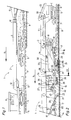
- a machine 1 shown in FIGS. 1 and 2 for processing a ballast bed and a formation has an elongated machine frame 2 which is formed from two frame parts 3, 4 which are connected to one another in an articulated manner and over all three rail bogies 5 is mounted on a track 8 composed of rails 6 and sleepers 7.
- the direction of travel of the machine 1 during work is indicated by an arrow 9.
- Both the middle, in the area of a hinge 10 of the machine frame 2 arranged rail chassis 5 as well as that - with respect to the direction of travel - rear end of the machine is designed to be displaceable in the longitudinal direction of the machine relative to the machine frame 2 with the aid of drives (not shown) (see position shown in broken lines).
- the front end of the machine 1 is equipped with a driving cabin 11 and a central power source 12 behind it for all drives and work units of the machine.
- a plow arrangement 13 is connected to the machine frame 2 immediately behind the foremost rail running gear 5.
- the rear frame part 4 of the machine 1 is bridge-shaped or cranked upward and has three track lifting devices 14, 15 and 16 spaced apart from one another in the machine longitudinal direction.
- the respective front and rear track lifting devices 14 and 16 which are adjacent to a rail running gear 5, are provided in a known manner with roller lifting tongs 17 that can be rolled off the rail head, and are connected to the machine frame 2 or the frame part 4 in a height-adjustable manner via link rods 18 and lifting drives 19 fastened to them.
- vertically adjustable, boom-like supports 20 are provided, which can be lowered on both longitudinal sides of the track 8 and are each equipped with brackets 21 at their free ends.
- these bedding processing tools such as. B.
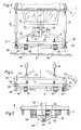
- the third, central track lifting device 15 is arranged below an operator's cab 24 fastened to the machine frame 2 and has a supporting body 25 with rolling elements 26 for supporting or supporting the sleepers 7, as will be described in more detail with reference to FIG. 3.
- a threshold scraper device 27 is connected to the machine frame 2 in a height-adjustable manner via a drive 28 and, in the lowered operating position, is guided on the track 8 by means of flange rollers 29.
- a conveyor belt arrangement 30 extends from the rear end of the machine 1 to a discharge point 31 arranged in the field of view of the operator cabin 24 and serves to take over bedding material from there to Machine 1 coupled transport carriage 32 and introduction of the material into the track 8.
- the conveyor belt arrangement 30 is provided with two discharge conveyor belts 33, which are mounted on the machine frame 2 so that they can be pivoted horizontally via support rollers 34.
- a funnel unit 35 which can be moved on the track 8 and which ensures that the dropped material is introduced between the sleepers 7 in a targeted manner and does not accumulate on them. For the transfer travel, the funnel unit 35 is lifted off the track 8 and stored by means of a holding device 36.
- the support body 25 of the track lifting device 15 running perpendicular to the machine longitudinal direction and parallel to the track plane is somewhat longer than a threshold 7 and is connected at both ends to a drive 37 articulated on the machine frame 2 or frame part 4.
- the structural unit 38 formed in this way by the supporting body 25 and drives 37 and supported exclusively on the machine frame 2 comprises the track 8 during use, which can be raised using the drives 37.
- the two rolling elements 26, which are connected to the support body 25 in the area below the rails 6 and are spaced apart from one another in the transverse direction of the machine, are designed as caterpillar tracks 39 which can be rolled off in the longitudinal direction of the machine.
- deflection rollers 41 which can be rotated about an axis 40 oriented in the cross-machine direction and which are spaced apart from one another in the longitudinal direction of the machine at a distance corresponding to approximately two sleeper divisions (FIG. 2).
- the diameter of the deflection rollers 41 is approximately half a threshold division.
- the support body 25 is further connected in the region of both ends opposite one another with respect to the cross-machine direction to supports 42 which are connected to the machine frame 2 in a common articulation point 43 which is distant in the longitudinal direction of the machine from the drives 37 and can be pivoted about a joint 44 which is effective on all sides.
- a swivel drive 45 running perpendicular to the longitudinal direction of the machine, by means of which the structural unit 38 can be pivoted about a vertical axis of the joint 44.
- Both the drives 37 and the supports 42 are connected to the support body 25 in a detachable manner, the articulation of the drives 37 and supports 42 being provided in the middle between the two deflection rollers 41 of a crawler belt 39 spaced apart in the machine longitudinal direction on the support body 25.
- the variant of a track lifting device 46 shown in FIG. 4 has a support body 47 which is designed as a frame 48 encircling the track 8 in the operating position.
- a horizontally running in the cross-machine direction, lower beam 49 of this frame is equipped with rolling elements 50, while drives 51 for height adjustment of the track lifting device 46 are detachably fastened to an upper beam 52 of the frame 48 and articulated on the machine frame (not shown).
- a vertical side part 53 of the frame is also detachably connected to the lower beam 49 and is pivotally supported on the upper beam 52 so that the track lifting device 46 can be brought into or out of use.
- the side part 53 and the opposite side part 54 of the frame 48 in the cross-machine direction are each connected to guide rollers 55, which are designed to be rotatable about a vertical axis 56 and are located in the immediate fore-head region of the sleepers 7 or can be rolled off on the sleeper ends 57 during use.
- FIG. 5 shows a rolling element 58 which is equipped with a number of rollers 59 arranged one behind the other in the machine longitudinal direction. These are each rotatably mounted about an axis 60 running in the cross-machine direction on a common bearing block 61, which in turn is rotatably mounted on a support body 62 about an axis 63 oriented in the cross-machine direction and is detachably connected to the latter.
- the distance between two adjacent rollers 59 is smaller than the width of a threshold 7.
- the rollers 59 roll in operation on the undersides of the sleepers 7, with guide rollers 64 being additionally provided on the support body 62, as already described in FIG. 4.
- the machine 1 can be used in different ways in the course of machining a track bed or a subgrade.
- z. B a protective layer of gravel or sand on the - previously cleaned using a cleaning machine from the gravel - earth level 65 installed.
- the plow arrangement 13 is not used.
- the middle rail undercarriage 5 is displaced into the foremost position with respect to the direction of travel, while the rear undercarriage 5 is adjusted in the opposite direction to the rear in order to create the largest possible span for the track 8 to be lifted. This is now lifted off the ground level 65 by means of the roller lifting tongs 17 of the track lifting devices 14 and 16, after which the central track lifting device 15 is brought into the operating position.
- the support body 25 supporting the rolling elements 26 is inserted under the sleepers 7 transversely to the track 8 and then - with the swivel drive 45 being controlled without pressure for the time being - connected to the drives 37 and the supports 42 at both longitudinal ends or longitudinal sides of the track.
- the track lifting device 15 at a rail separation point under the track grate, the assembly 38 not having to be disassembled into its individual parts.
- the track is now supported and secured from below via the crawler tracks 39 of the track lifting device 15, while the machine 1 is continuously advancing in the direction of the arrow 9.
- the drives 19 and 37 the extent of the track lifting is controlled or adapted to the circumstances.
- the leveling bar 65 is smoothed with the leveling bar 22, onto which gravel 66 is then thrown off via the conveyor belt arrangement 30 and pulled off by means of the distribution bar 67 and compacted using the trailing vibrating plates 23.
- the track 8 is subsequently deposited on the compacted formation protection layer via the rear track lifting device 16.
- a work train is moved over the installation site on the lowered track 8 lying on the earth level 65 or on the already installed formation protection layer, ballast ballast is removed from Talbot wagons and the track grating is thus completely filled.
- the subsequent machine 1 now lifts the track 8 again and levels or compresses the bedding material that has been thrown off and distributed over the track cross section by means of the plow arrangement 13 analogously to the previously described working variant.
Landscapes
- Engineering & Computer Science (AREA)
- Architecture (AREA)
- Civil Engineering (AREA)
- Structural Engineering (AREA)
- Machines For Laying And Maintaining Railways (AREA)
- Electrical Discharge Machining, Electrochemical Machining, And Combined Machining (AREA)
- Materials For Photolithography (AREA)
- Lighting Device Outwards From Vehicle And Optical Signal (AREA)
- Soil Working Implements (AREA)
Applications Claiming Priority (2)
| Application Number | Priority Date | Filing Date | Title |
|---|---|---|---|
| AT72093 | 1993-04-08 | ||
| AT720/93 | 1993-04-08 |
Publications (3)
| Publication Number | Publication Date |
|---|---|
| EP0619400A2 true EP0619400A2 (fr) | 1994-10-12 |
| EP0619400A3 EP0619400A3 (fr) | 1995-03-29 |
| EP0619400B1 EP0619400B1 (fr) | 1998-05-13 |
Family
ID=3498036
Family Applications (1)
| Application Number | Title | Priority Date | Filing Date |
|---|---|---|---|
| EP94890052A Expired - Lifetime EP0619400B1 (fr) | 1993-04-08 | 1994-03-04 | Machine pour travailler un ballast ou un palier de voie |
Country Status (12)
| Country | Link |
|---|---|
| US (1) | US5435252A (fr) |
| EP (1) | EP0619400B1 (fr) |
| CN (1) | CN1066226C (fr) |
| AT (1) | ATE166120T1 (fr) |
| AU (1) | AU666807B2 (fr) |
| CA (1) | CA2120822C (fr) |
| CZ (1) | CZ32094A3 (fr) |
| DE (1) | DE59405934D1 (fr) |
| ES (1) | ES2118360T3 (fr) |
| FI (1) | FI108658B (fr) |
| PL (1) | PL173312B1 (fr) |
| RU (1) | RU2093632C1 (fr) |
Cited By (2)
| Publication number | Priority date | Publication date | Assignee | Title |
|---|---|---|---|---|
| EP2022896A1 (fr) * | 2007-08-08 | 2009-02-11 | Deutsche Gleis-und Tiefbau GmbH | Wagon ferroviaire de chargement de matières en vrac |
| WO2013023746A1 (fr) * | 2011-08-18 | 2013-02-21 | Franz Plasser Bahnbaumaschinen-Industriegesellschaft Mbh | Machine de rénovation d'une voie ferrée |
Families Citing this family (3)
| Publication number | Priority date | Publication date | Assignee | Title |
|---|---|---|---|---|
| GB0406945D0 (en) * | 2004-03-27 | 2004-04-28 | W & D Mcculloch | Rail track handling apparatus and method |
| AT513824B1 (de) * | 2013-02-25 | 2014-08-15 | Plasser Bahnbaumasch Franz | Maschine zur Reinigung von Schotter eines Gleises |
| RU2572485C1 (ru) * | 2014-07-28 | 2016-01-10 | Игорь Анатольевич Пухов | Способ строительства и ремонта бесстыкового пути, рельсошпальная решётка и путеукладочный поезд для его осуществления |
Family Cites Families (14)
| Publication number | Priority date | Publication date | Assignee | Title |
|---|---|---|---|---|
| CA523843A (fr) * | 1956-04-17 | I. S. Fogelberg Tord | Appareil pour soulever des rails de chemin de fer | |
| US1338681A (en) * | 1920-02-10 | 1920-05-04 | Dobson Daniel Jefferson | Machine for ballasting railway-tracks |
| US1899874A (en) * | 1930-07-28 | 1933-02-28 | Lemaire Maurice Henri | System for continuously cleaning the ballast of railway tracks |
| DE571197C (de) * | 1932-03-25 | 1933-02-24 | Rheinische Metallw & Maschf | Vorrichtung zum OEffnen und Schliessen der Auswurfoeffnung fuer die Geschosshuelsen von gegen die Aussenluft gasdicht abgeschlossenen Geschuetzraeumen |
| CH291134A (fr) * | 1950-03-10 | 1953-06-15 | Lemaire Maurice Henri | Procédé et machine pour la rénovation et l'amélioration du ballast des voies ferrées. |
| GB695900A (en) * | 1950-03-10 | 1953-08-19 | Maurice Henri Lemaire | Improvements in or relating to methods of, and plants for, railroad ballast maintenance |
| US2725016A (en) * | 1950-07-07 | 1955-11-29 | Fogelberg Tord Ivar Svante | Apparatus for lifting railway tracks |
| US2737901A (en) * | 1950-11-17 | 1956-03-13 | Drouard Jacques | Machine for clearing away the ballast from under the railway track sleepers |
| FR1122989A (fr) * | 1955-04-25 | 1956-09-14 | Dégarnisseuse pour voies de chemin de fer | |
| US3055309A (en) * | 1957-10-28 | 1962-09-25 | Lloyd E Moss | Combination track lifting and ballast removing machine |
| US3179002A (en) * | 1961-12-15 | 1965-04-20 | Bausch & Lomb | Projector system |
| AT345881B (de) * | 1975-08-18 | 1978-10-10 | Plasser Bahnbaumasch Franz | Fahrbare maschine zum kontinuierlichen nivellieren und verdichten der schotterbettung eines gleises |
| AT379176B (de) * | 1981-12-22 | 1985-11-25 | Plasser Bahnbaumasch Franz | Fahrbare anlage und verfahren zur kontinuierlich fortschreitenden sanierung des gleisunterbaues |
| AT398097B (de) * | 1991-11-13 | 1994-09-26 | Plasser Bahnbaumasch Franz | Anlage zur herstellung einer planumschutzschichte |
-
1994
- 1994-02-15 CZ CZ94320A patent/CZ32094A3/cs not_active IP Right Cessation
- 1994-03-04 DE DE59405934T patent/DE59405934D1/de not_active Expired - Lifetime
- 1994-03-04 AT AT94890052T patent/ATE166120T1/de active
- 1994-03-04 ES ES94890052T patent/ES2118360T3/es not_active Expired - Lifetime
- 1994-03-04 EP EP94890052A patent/EP0619400B1/fr not_active Expired - Lifetime
- 1994-03-24 RU RU9494010053A patent/RU2093632C1/ru not_active IP Right Cessation
- 1994-03-29 PL PL94302831A patent/PL173312B1/pl not_active IP Right Cessation
- 1994-04-06 US US08/223,594 patent/US5435252A/en not_active Expired - Lifetime
- 1994-04-07 CA CA002120822A patent/CA2120822C/fr not_active Expired - Fee Related
- 1994-04-07 AU AU59299/94A patent/AU666807B2/en not_active Ceased
- 1994-04-07 FI FI941603A patent/FI108658B/fi not_active IP Right Cessation
- 1994-04-08 CN CN94103931A patent/CN1066226C/zh not_active Expired - Fee Related
Cited By (2)
| Publication number | Priority date | Publication date | Assignee | Title |
|---|---|---|---|---|
| EP2022896A1 (fr) * | 2007-08-08 | 2009-02-11 | Deutsche Gleis-und Tiefbau GmbH | Wagon ferroviaire de chargement de matières en vrac |
| WO2013023746A1 (fr) * | 2011-08-18 | 2013-02-21 | Franz Plasser Bahnbaumaschinen-Industriegesellschaft Mbh | Machine de rénovation d'une voie ferrée |
Also Published As
| Publication number | Publication date |
|---|---|
| CN1101692A (zh) | 1995-04-19 |
| CA2120822C (fr) | 2004-11-09 |
| DE59405934D1 (de) | 1998-06-18 |
| AU5929994A (en) | 1994-10-13 |
| ES2118360T3 (es) | 1998-09-16 |
| CN1066226C (zh) | 2001-05-23 |
| EP0619400B1 (fr) | 1998-05-13 |
| CZ279539B6 (cs) | 1995-05-17 |
| FI941603A0 (fi) | 1994-04-07 |
| CZ32094A3 (en) | 1995-05-17 |
| EP0619400A3 (fr) | 1995-03-29 |
| ATE166120T1 (de) | 1998-05-15 |
| AU666807B2 (en) | 1996-02-22 |
| PL173312B1 (pl) | 1998-02-27 |
| RU94010053A (ru) | 1996-06-10 |
| US5435252A (en) | 1995-07-25 |
| FI941603L (fi) | 1994-10-09 |
| FI108658B (fi) | 2002-02-28 |
| RU2093632C1 (ru) | 1997-10-20 |
| CA2120822A1 (fr) | 1994-10-09 |
Similar Documents
| Publication | Publication Date | Title |
|---|---|---|
| DE2550391C2 (de) | Verfahren zum Entnehmen von Bettungsmaterial aus Schotterbettungen | |
| DE3333262C2 (fr) | ||
| EP0255564B1 (fr) | Machine pour remplacer ou rénover respectivement les rails et les traverses d'une voie existante | |
| EP1162312B1 (fr) | Machine pour le renouvellement d'une voie ferrée | |
| DE2818514C2 (fr) | ||
| DD284067A5 (de) | Fahrbare gleisstopf-, hebe- und richtmaschine zum heben und bzw. oder seitwaertsverschieben eines gleises im weichen- und kreuzungsbereich | |
| AT402952B (de) | Gleisbaumaschine zum kontrollierten absenken einesgleises | |
| EP1253247B1 (fr) | Machine pour nettoyer le ballast d' une voie ferrée | |
| EP0670932B1 (fr) | Machine de pose de voie pour le renouvellement des voies ferrees | |
| EP0408839A1 (fr) | Ensemble de machines déplaçable sur voie pour enlever, nettoyer et remettre en place le ballast d'une voie ferrée | |
| EP0771909B1 (fr) | Machine pour le démontage d'une ancienne voie ferrée et l'installation d'une nouvelle voie | |
| DE3106754A1 (de) | Gleisbaumaschine mit werkzeugtraeger fuer hebe- und richtwerkzeuge | |
| EP0609647B1 (fr) | Machine pour le renouvellement ou nettoyage d'un lit de ballast | |
| DD284068A5 (de) | Gleisumbauzug | |
| DE1658339C3 (de) | Gleisstopf- und Richtmaschine | |
| DE3819717A1 (de) | Kontinuierlich (non-stop) verfahrbare gleisbaumaschine | |
| EP0342306B1 (fr) | Machine pour ripage latéral d'une voie constituée de rails et de traverses transversales | |
| EP0416135B1 (fr) | Machine mobile sur rails pour distribuer et profiler le lit de ballast d'une voie ferrée | |
| EP1253248B1 (fr) | Méthode et machine pour nettoyer le ballast | |
| EP0056497A1 (fr) | Wagon-cadre dans un train pour effectuer l'assainissement du sous-sol des voies de chemin de fer | |
| DE3106063A1 (de) | Gleisbaumaschine mit einer schotterbett-raeum- und planiervorrichtung | |
| AT411276B (de) | Maschine zur bearbeitung eines gleises | |
| EP0619400B1 (fr) | Machine pour travailler un ballast ou un palier de voie | |
| EP1285996B1 (fr) | Machine de construction pour ballast de voies ferrées | |
| EP0397956A1 (fr) | Machine de bourrage, mobile de façon continue, comportant un dispositif de charrue |
Legal Events
| Date | Code | Title | Description |
|---|---|---|---|
| PUAI | Public reference made under article 153(3) epc to a published international application that has entered the european phase |
Free format text: ORIGINAL CODE: 0009012 |
|
| AK | Designated contracting states |
Kind code of ref document: A2 Designated state(s): AT CH DE ES FR GB IT LI NL SE |
|
| 17P | Request for examination filed |
Effective date: 19941024 |
|
| PUAL | Search report despatched |
Free format text: ORIGINAL CODE: 0009013 |
|
| AK | Designated contracting states |
Kind code of ref document: A3 Designated state(s): AT CH DE ES FR GB IT LI NL SE |
|
| 17Q | First examination report despatched |
Effective date: 19970110 |
|
| GRAG | Despatch of communication of intention to grant |
Free format text: ORIGINAL CODE: EPIDOS AGRA |
|
| GRAG | Despatch of communication of intention to grant |
Free format text: ORIGINAL CODE: EPIDOS AGRA |
|
| GRAH | Despatch of communication of intention to grant a patent |
Free format text: ORIGINAL CODE: EPIDOS IGRA |
|
| GRAH | Despatch of communication of intention to grant a patent |
Free format text: ORIGINAL CODE: EPIDOS IGRA |
|
| GRAA | (expected) grant |
Free format text: ORIGINAL CODE: 0009210 |
|
| AK | Designated contracting states |
Kind code of ref document: B1 Designated state(s): AT CH DE ES FR GB IT LI NL SE |
|
| REF | Corresponds to: |
Ref document number: 166120 Country of ref document: AT Date of ref document: 19980515 Kind code of ref document: T |
|
| REG | Reference to a national code |
Ref country code: CH Ref legal event code: EP |
|
| ITF | It: translation for a ep patent filed | ||
| GBT | Gb: translation of ep patent filed (gb section 77(6)(a)/1977) |
Effective date: 19980513 |
|
| REF | Corresponds to: |
Ref document number: 59405934 Country of ref document: DE Date of ref document: 19980618 |
|
| ET | Fr: translation filed | ||
| REG | Reference to a national code |
Ref country code: ES Ref legal event code: FG2A Ref document number: 2118360 Country of ref document: ES Kind code of ref document: T3 |
|
| PLBE | No opposition filed within time limit |
Free format text: ORIGINAL CODE: 0009261 |
|
| STAA | Information on the status of an ep patent application or granted ep patent |
Free format text: STATUS: NO OPPOSITION FILED WITHIN TIME LIMIT |
|
| 26N | No opposition filed | ||
| REG | Reference to a national code |
Ref country code: GB Ref legal event code: IF02 |
|
| PGFP | Annual fee paid to national office [announced via postgrant information from national office to epo] |
Ref country code: NL Payment date: 20110329 Year of fee payment: 18 Ref country code: SE Payment date: 20110325 Year of fee payment: 18 Ref country code: AT Payment date: 20110211 Year of fee payment: 18 Ref country code: CH Payment date: 20110325 Year of fee payment: 18 |
|
| PGFP | Annual fee paid to national office [announced via postgrant information from national office to epo] |
Ref country code: ES Payment date: 20110323 Year of fee payment: 18 Ref country code: FR Payment date: 20110407 Year of fee payment: 18 Ref country code: GB Payment date: 20110301 Year of fee payment: 18 |
|
| PGFP | Annual fee paid to national office [announced via postgrant information from national office to epo] |
Ref country code: DE Payment date: 20110513 Year of fee payment: 18 Ref country code: IT Payment date: 20110329 Year of fee payment: 18 |
|
| REG | Reference to a national code |
Ref country code: NL Ref legal event code: V1 Effective date: 20121001 |
|
| REG | Reference to a national code |
Ref country code: SE Ref legal event code: EUG |
|
| PG25 | Lapsed in a contracting state [announced via postgrant information from national office to epo] |
Ref country code: SE Free format text: LAPSE BECAUSE OF NON-PAYMENT OF DUE FEES Effective date: 20120305 |
|
| REG | Reference to a national code |
Ref country code: CH Ref legal event code: PL |
|
| GBPC | Gb: european patent ceased through non-payment of renewal fee |
Effective date: 20120304 |
|
| REG | Reference to a national code |
Ref country code: AT Ref legal event code: MM01 Ref document number: 166120 Country of ref document: AT Kind code of ref document: T Effective date: 20120304 |
|
| REG | Reference to a national code |
Ref country code: FR Ref legal event code: ST Effective date: 20121130 |
|
| PG25 | Lapsed in a contracting state [announced via postgrant information from national office to epo] |
Ref country code: GB Free format text: LAPSE BECAUSE OF NON-PAYMENT OF DUE FEES Effective date: 20120304 Ref country code: FR Free format text: LAPSE BECAUSE OF NON-PAYMENT OF DUE FEES Effective date: 20120402 Ref country code: LI Free format text: LAPSE BECAUSE OF NON-PAYMENT OF DUE FEES Effective date: 20120331 Ref country code: AT Free format text: LAPSE BECAUSE OF NON-PAYMENT OF DUE FEES Effective date: 20120304 Ref country code: CH Free format text: LAPSE BECAUSE OF NON-PAYMENT OF DUE FEES Effective date: 20120331 |
|
| REG | Reference to a national code |
Ref country code: DE Ref legal event code: R119 Ref document number: 59405934 Country of ref document: DE Effective date: 20121002 |
|
| PG25 | Lapsed in a contracting state [announced via postgrant information from national office to epo] |
Ref country code: IT Free format text: LAPSE BECAUSE OF NON-PAYMENT OF DUE FEES Effective date: 20120304 |
|
| PG25 | Lapsed in a contracting state [announced via postgrant information from national office to epo] |
Ref country code: NL Free format text: LAPSE BECAUSE OF NON-PAYMENT OF DUE FEES Effective date: 20121001 |
|
| REG | Reference to a national code |
Ref country code: ES Ref legal event code: FD2A Effective date: 20130710 |
|
| PG25 | Lapsed in a contracting state [announced via postgrant information from national office to epo] |
Ref country code: ES Free format text: LAPSE BECAUSE OF NON-PAYMENT OF DUE FEES Effective date: 20120305 |
|
| PG25 | Lapsed in a contracting state [announced via postgrant information from national office to epo] |
Ref country code: DE Free format text: LAPSE BECAUSE OF NON-PAYMENT OF DUE FEES Effective date: 20121002 |