EP0619574A1 - Sprachkodierer mit Analyse-durch Synthese-Technik und Pulsanregung - Google Patents
Sprachkodierer mit Analyse-durch Synthese-Technik und Pulsanregung Download PDFInfo
- Publication number
- EP0619574A1 EP0619574A1 EP94105438A EP94105438A EP0619574A1 EP 0619574 A1 EP0619574 A1 EP 0619574A1 EP 94105438 A EP94105438 A EP 94105438A EP 94105438 A EP94105438 A EP 94105438A EP 0619574 A1 EP0619574 A1 EP 0619574A1
- Authority
- EP
- European Patent Office
- Prior art keywords
- signal
- samples
- filtering
- long
- excitation
- Prior art date
- Legal status (The legal status is an assumption and is not a legal conclusion. Google has not performed a legal analysis and makes no representation as to the accuracy of the status listed.)
- Withdrawn
Links
Images


Classifications
-
- G—PHYSICS
- G10—MUSICAL INSTRUMENTS; ACOUSTICS
- G10L—SPEECH ANALYSIS TECHNIQUES OR SPEECH SYNTHESIS; SPEECH RECOGNITION; SPEECH OR VOICE PROCESSING TECHNIQUES; SPEECH OR AUDIO CODING OR DECODING
- G10L19/00—Speech or audio signals analysis-synthesis techniques for redundancy reduction, e.g. in vocoders; Coding or decoding of speech or audio signals, using source filter models or psychoacoustic analysis
- G10L19/04—Speech or audio signals analysis-synthesis techniques for redundancy reduction, e.g. in vocoders; Coding or decoding of speech or audio signals, using source filter models or psychoacoustic analysis using predictive techniques
- G10L19/08—Determination or coding of the excitation function; Determination or coding of the long-term prediction parameters
- G10L19/12—Determination or coding of the excitation function; Determination or coding of the long-term prediction parameters the excitation function being a code excitation, e.g. in code excited linear prediction [CELP] vocoders
-
- G—PHYSICS
- G10—MUSICAL INSTRUMENTS; ACOUSTICS
- G10L—SPEECH ANALYSIS TECHNIQUES OR SPEECH SYNTHESIS; SPEECH RECOGNITION; SPEECH OR VOICE PROCESSING TECHNIQUES; SPEECH OR AUDIO CODING OR DECODING
- G10L19/00—Speech or audio signals analysis-synthesis techniques for redundancy reduction, e.g. in vocoders; Coding or decoding of speech or audio signals, using source filter models or psychoacoustic analysis
- G10L19/04—Speech or audio signals analysis-synthesis techniques for redundancy reduction, e.g. in vocoders; Coding or decoding of speech or audio signals, using source filter models or psychoacoustic analysis using predictive techniques
- G10L19/08—Determination or coding of the excitation function; Determination or coding of the long-term prediction parameters
- G10L19/10—Determination or coding of the excitation function; Determination or coding of the long-term prediction parameters the excitation function being a multipulse excitation
-
- G—PHYSICS
- G10—MUSICAL INSTRUMENTS; ACOUSTICS
- G10L—SPEECH ANALYSIS TECHNIQUES OR SPEECH SYNTHESIS; SPEECH RECOGNITION; SPEECH OR VOICE PROCESSING TECHNIQUES; SPEECH OR AUDIO CODING OR DECODING
- G10L19/00—Speech or audio signals analysis-synthesis techniques for redundancy reduction, e.g. in vocoders; Coding or decoding of speech or audio signals, using source filter models or psychoacoustic analysis
- G10L2019/0001—Codebooks
- G10L2019/0003—Backward prediction of gain
-
- G—PHYSICS
- G10—MUSICAL INSTRUMENTS; ACOUSTICS
- G10L—SPEECH ANALYSIS TECHNIQUES OR SPEECH SYNTHESIS; SPEECH RECOGNITION; SPEECH OR VOICE PROCESSING TECHNIQUES; SPEECH OR AUDIO CODING OR DECODING
- G10L19/00—Speech or audio signals analysis-synthesis techniques for redundancy reduction, e.g. in vocoders; Coding or decoding of speech or audio signals, using source filter models or psychoacoustic analysis
- G10L2019/0001—Codebooks
- G10L2019/0011—Long term prediction filters, i.e. pitch estimation
-
- G—PHYSICS
- G10—MUSICAL INSTRUMENTS; ACOUSTICS
- G10L—SPEECH ANALYSIS TECHNIQUES OR SPEECH SYNTHESIS; SPEECH RECOGNITION; SPEECH OR VOICE PROCESSING TECHNIQUES; SPEECH OR AUDIO CODING OR DECODING
- G10L19/00—Speech or audio signals analysis-synthesis techniques for redundancy reduction, e.g. in vocoders; Coding or decoding of speech or audio signals, using source filter models or psychoacoustic analysis
- G10L2019/0001—Codebooks
- G10L2019/0012—Smoothing of parameters of the decoder interpolation
-
- G—PHYSICS
- G10—MUSICAL INSTRUMENTS; ACOUSTICS
- G10L—SPEECH ANALYSIS TECHNIQUES OR SPEECH SYNTHESIS; SPEECH RECOGNITION; SPEECH OR VOICE PROCESSING TECHNIQUES; SPEECH OR AUDIO CODING OR DECODING
- G10L19/00—Speech or audio signals analysis-synthesis techniques for redundancy reduction, e.g. in vocoders; Coding or decoding of speech or audio signals, using source filter models or psychoacoustic analysis
- G10L2019/0001—Codebooks
- G10L2019/0013—Codebook search algorithms
- G10L2019/0014—Selection criteria for distances
-
- G—PHYSICS
- G10—MUSICAL INSTRUMENTS; ACOUSTICS
- G10L—SPEECH ANALYSIS TECHNIQUES OR SPEECH SYNTHESIS; SPEECH RECOGNITION; SPEECH OR VOICE PROCESSING TECHNIQUES; SPEECH OR AUDIO CODING OR DECODING
- G10L25/00—Speech or voice analysis techniques not restricted to a single one of groups G10L15/00 - G10L21/00
- G10L25/03—Speech or voice analysis techniques not restricted to a single one of groups G10L15/00 - G10L21/00 characterised by the type of extracted parameters
- G10L25/24—Speech or voice analysis techniques not restricted to a single one of groups G10L15/00 - G10L21/00 characterised by the type of extracted parameters the extracted parameters being the cepstrum
Definitions
- the present invention relates to speech coders employing analysis-by-synthesis techniques, and more particularly to a coder for low-bit-rate applications, preferably at the lowest limits of the range of rates for which the above-mentioned coders can be used with good performance, e.g. rates within the 4 - 8 kbit/s range.
- Speech coders to be used for the so-called half-rate channel of the European mobile radio system.
- the excitation signal for the synthesis filter simulating the speech production apparatus is chosen within a set of excitation signals so as to minimize a perceptually meaningful measure of distortion. This is commonly obtained through the comparison of the synthesized samples and of the corresponding samples of the original signal and the simultaneous weighting, in a suitable filter, with a function that takes into account how human perception evaluates the resulting distortion.
- the synthesis filter includes a cascade of two elements that impose short-term and long-term spectral features, respectively, on the excitation signal.
- the former ones are linked to the correlation among subsequent samples, which generates a non-flat spectral envelope, and the latter ones are linked to the correlation between adjacent pitch periods, on which the fine signal spectral structure depends.
- the coded signal includes information relating to excitation and to short-term synthesis parameters (short-term linear prediction coefficients or other quantities related to them) and long-term ones (long-term delay and linear prediction coefficients).
- the paper suggests to modify the original signal so that long-term predictor parameters become known functions of time and allow a direct interpolation without degrading performance.
- the suggested modifications consist of limited time oscillations and small amplitude scalings of the original signal. Time oscillations can be carried out in discrete manner. The need for inserting these time oscillations, and therefore for setting an optimal amount thereof, obviously increases the coder complexity.
- a coding system in which, before long-term analysis, discrete time shifts are introduced on the residual signals and in which the search for optimal excitation signal and optimal shift is carried out so as to reduce complexity of computations.
- the coder receives samples x(n) of the speech signal to be coded, grouped into blocks (commonly called 'frames') including a fixed number Lf of contiguous samples. Every frame of Lf samples is then divided into subframes of Ls contiguous samples.
- the coder must determine a set of parameters to be transmitted to the decoder so that the decoder is able to synthesize a signal that approximates the original signal. To achieve this, an analysis-by-synthesis procedure is used, through which the coder analyzes the effects of the possible values of each parameter and chooses the value that enables obtaining the best approximation of the original signal.
- the coder will contain a replica of the decoder to produce, for each of said values, the corresponding output signal.
- both long-term and short-term correlations of the speech signal are exploited, imposed on an excitation signal through respective synthesis filters.
- the coder carries out a linear prediction analysis (short-term or LPC analysis) and computes the short-term residual signal, that is used to compute parameters (delay and coefficient) of the long-term synthesis filter. (The coefficient is unique in the preferred embodiment, since a first-order filter is used).
- both the delay and the coefficient are interpolated when the delays of the current frame and the previous frame are close in value.
- the shift amount is determined through an exhaustive search in a range of possible values so as to minimize the energy of the error (difference between original signal and reconstructed signal). After having determined the optimal shift, the search for the optimal excitation signal is carried out.
- CELP Codebook Excited Linear Prediction
- the coded signal will include information related to short-term and long-term synthesis filter parameters and to the optimal excitation, transmitted as usual in the form of suitably coded indexes.
- an excitation signal corresponding to the one used by the coder will be retrieved and filtered in the chain of a long-term synthesis filter and a short-term synthesis filter to provide a reconstructed signal that can be still subjected to a further filtering (post-filtering), based for example on short-term synthesis parameters, to improve the subjective signal quality.
- post-filtering based for example on short-term synthesis parameters
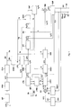
- Samples read in MT are supplied to a high-pass filter FPA whose task is removing d.c. drifts and low-frequency noise, and the filtered signal x f (n) is supplied to short-term analysis circuits STA and to a linear prediction filter LPC.
- Circuits STA are to determine, for each frame, a set of P linear prediction coefficients a i (e.g. 10), to convert these coefficients into a group of parameters in the frequency domain, commonly known as LSP (Line Spectrum Pairs) and to carry out a quantization, for example a scalar one, of the differences between adjacent parameters.
- Indexes j(f) that are part of the coded signal, are transmitted to the decoder through a connection 2a after binary coding in circuits that are not shown. Conversion into line spectrum pairs is desirable since, as well known, spectrum lines have properties of quantization, interpolation and check of synthesis filter stability that are better than those of the coefficients.
- a smoothing of spectrum information related to formants is also carried out to match it to the quantization circuit resolution. This is accomplished by multiplying computed coefficients a i by a respective factor g1 i , whose value is typically less than 1 but quite near 1. This operation allows reducing the risk, in case of particularly narrow formants, of reproducing after quantization formants that are equally narrow, but shifted with respect to the original ones, and therefore reduces a possible cause for the degradation of coded signal quality.
- the circuit STA computes coefficients a i according to the classical autocorrelation method, as described in "Digital Signal Processing of Speech Signals” by L.R. Rabiner and R.W. Schafer (Prentice - Hall Ed., Englewood Cliffs, N.J., USA, 1978), p. 401.
- STA operates on a set of Lf+P input samples (in particular, the samples that occupy the last Lf+P positions in MT), obtained through a trapezoidal window that weights with a maximum weight (particularly 1) all samples except for the first and the last P ones, for which the weights have been determined with a simple linear interpolation operation between minimum and maximum weight: in this way, smoothing, that is required by the autocorrelation method to provide good results, is limited to the overlapping area between contiguous windows.
- the forward positioning of the window also takes into account the fact that, when coding the initial subframes of a frame (e.g.
- coefficients are used which are obtained by the conversion of line spectrum pair values determined through interpolation between values related to the previous frame and values related to the current frame. This ensures a gradual transition between current frame parameters and previous frame parameters.
- the window as explained, it encompasses or spans over a current frame and the subsequent frame in the meaning that it comprises samples of both frames without, however, having to comprise two full frames.
- STA The operations of STA are typical of any linear prediction coder, and therefore a more detailed description is not necessary.
- the indexes j( ⁇ ) are also supplied to a linear prediction coefficient reconstructing circuit STR1 that supplies filter LPC, short-term synthesis filters STS1, STS' and spectral weighting filters SW, SW' with quantized values of the coefficients, obtained by applying inverse procedures with respect to the ones used to transform the coefficients into line spectrum pairs.
- STR1 also computes interpolated values to be used in the first three subframes. To simplify, in the following, the quantized values are also designated a i .
- the filter LPC receives the filtered speech signal samples x f (n) and filters them according to the conventional function generating the short-term prediction residual r s (n), that is supplied both to a low-pass filter FPB, that produces a filtered residual signal r f (n), and to time shift circuits TS, that produce a modified residual signal r m (n).
- Low-pass filtering facilitates, as well known, operations of a following long-term analysis circuits LTA.
- the circuits LTA must determine, at each frame, and supply afollowing long-term synthesis filter LTS1 with the delay d (pitch period) with which a sample of an excitation signal is used to generate a reconstructed signal and the gain or coefficient b with which said sample is weighted.
- the block LTA computes the delay d by maximizing the autocorrelation function where k can vary between a minimum value and a maximum value allowed for the delay d (e.g., 20 and 120), and x is a preset number, whose purpose is causing the length of the window taken into account for the calculation to enable obtaining a satisfactory value for d.
- the window must include the most recent samples, as already said, its length is a compromise between two opposed needs: the greater the length, the most accurate the evaluation; on the other hand, the shorter the window, the more its center is next to the end of the frame to be coded (Lf samples) and therefore it allows obtaining a current value next to that end, what is required for interpolation.
- x can be K.
- the delay is never less than the length of a subframe, and this simplifies considerably subsequent operations.
- the value computed with (1) can also be subjected to corrections, that will be examined afterwards, aimed at guaranteeing a shape as much as possible smooth for d and compensating for synchronism losses due to the time shift.
- b R[r f (d)]/E(r f ) , where E(r f ) indicates the energy
- E(r f ) indicates the energy
- a minimum and a maximum, 0 and 1 respectively, are also set for the value of b. Values that are less than 0 are excluded because they would correspond to a signal overturning, that would also compel to transmit a sign bit, while values that are greater than 1 make the filter unstable, as well known.
- the value of b computed using (2) can also be subjected to corrections aimed at guaranteeing the best quality of the coded signal. Furthermore, in certain frames, instead of the values d and b computed with (1) and (2), it is possible to use values obtained by linear interpolation between values computed for the previous frame and values computed for the current frame.
- the prediction gain G is also computed: this is a quantity representing the ratio between the energies of input and output signals from the long-term predictor and gives a measure of long-term prediction efficiency.
- Gain G is defined by the expression where 1 - bR[r f (d)]/E'(r f )
- Gain G allows establishing whether the speech segment being coded is voiced, that is indicated by values of G and b that are both greater than respective thresholds G thr , b thr .
- LTA generates a flag V that is used to decide to carry out the interpolation and to introduce the time shift.
- a first correction for delay d is based on the search for the local maximum of function (1) also in a given neighborhood (e.g., ⁇ 15%) of the value obtained at the previous frame: if this local maximum is different from the main maximum by an amount that is less than a certain limit, that new value is used that provides a more smooth outline that can be therefore interpolated.
- This secondary search is carried out only if the signal in the previous frame was strongly voiced and had been subjected to interpolation.
- the correction, if any, is carried out before computing b and G, so as to use the already corrected value of d for these computations.
- a second correction is linked to the presence of the time shift mechanism, that inserts a variable delay whose effects can be compared to those of a non-synchronous operation of the coder.
- each 8 kHz sample will originate eight samples at 64 kHz.
- the correction can be carried out if interpolation is required in the current frame and if the speech segment is not voiced.
- the first condition is necessary since, if the interpolation is absent, no shift is carried out; moreover, the signal must not be voiced because in this situation an even minimal modification of d with respect to the exact value can usually be perceived.
- its absolute value is limited to a maximum value ⁇ d' ⁇ max , for example 1.
- the correction is carried out only if it does not modify the decision about interpolation (that will be described afterwards) and does not take the value of d outside the provided range of values.
- a first correction consists of clipping b to a first upper limit b1, since, if b is too high, an excessive energy increase would occur, which gives rise to noises.
- the correction is carried out if the energy in the previous frame exceeds a certain threshold.
- a further limitation for b is carried out in case of low values of G (less than G thr ), that show speech segments with low periodicity, while b is relatively high (greater than a second limit b2): in this case, the value b2 is employed, since employing the actual value could produce artifacts in the coded signal.
- interpolation this is carried out if the relative variation of d between two consecutive frames does not exceed, as absolute value, a predetermined amount (e.g., 15%) and if the values of b in these frames are both positive.
- a predetermined amount e.g. 15%
- the actual computation of the values of d and b to be used in case of interpolation is carried out in the long-term synthesis filter LTS1, to which LTA sends a flag F when the above mentioned conditions are verified.
- the same flag is also supplied to an error energy minimizing circuit EM determining the optimal time shift and excitation.
- index j(d), j(b) are the information related to long-term analysis to be inserted into the coded signal, and that are transmitted to the decoder, after suitable coding, through connections 2b, 2c.
- Index j(b) is determined through a quantization operation, during which, in addition to limiting the maximum value to 1, values of b that are less than half of the first quantized value are forced to 0. No quantization of d is however necessary, since d is already a discrete quantity: it is however preferable to transmit d under the form of an index for sake of uniformity with the other information.
- the conversion of the values of d into indexes practically consists of their shift, such as to make the possible range of values begin from 1 instead of from a value d min .
- 7 bits will be necessary to code index j(d), and these bits will also allow coding of values of j(d) outside the provided range.
- index j(b) corresponding to the minimum value of b is transmitted.
- circuits generating indexes j(b), j(d) are included into block LTA.
- circuit LTA can take decisions related to the sound nature and the need to carry out interpolation and therefore shift.
- LTA operations performed by LTA are described in detail in the appendix, that includes program listing in C language. Given the listing, a technician has no problem in designing devices that perform the described functions.
- Indexes j(d), j(b) are reconverted into quantized or reconstructed values of the respective parameters by reconstructing circuits LTR1, composed of simple read-only memories addressed by the indexes.
- LTR1 provides the actual values of d, b if j(d) shows a value allowed for the delay (that is, if j(d) is in the range 1 to 101). If j(d) shows any one of the values outside the allowed range (therefore its value is from 102 to 127), LTR1 provides value 0 for b and value d min for d.
- This one is composed of a shape information (innovation), represented by one of the words s(n) of an innovation codebook IC1, by a positive or null amplitude parameter g (innovation gain), chosen in a codebook of innovation gains IG1, and by a sign information, represented by a parameter ⁇ (innovation sign) whose value is ⁇ 1.
- codebook IG1 Even if, to facilitate understanding, codebooks IC1, IG1 are represented as circuit blocks (that could suggest the idea of memories that contain them), as said above, the particular structure of innovation codebook makes their storage superfluous. The structure of innovation and gain codebooks will be examined later.
- Symbols d0, b0 show the values related to the current frame, d(-1), b(-1) those related to the previous frame.
- the interpolation is therefore a linear one and extends over a whole frame.
- the values of d(n) and b(n) then vary sample by sample.
- d(n) it will generally not be an integer number: this means that the value of signal s s (n) at the continuous time instant n-d(n) does not coincide with that of an actually available sample and must be evaluated: according to the invention, evaluation is performed through a second order polynomial interpolation (that is through a parabola) centered about the discrete time instant that is nearest to n-d(n); the value thus evaluated is then multiplied by the interpolated value b(n).
- the interpolation procedure adopted has an extremely lower computation complexity than more sophisticated interpolation methods based on signal filtering. However, its effect is essentially a low-pass one, that is useful for the good operation of the coder since it avoids that the reconstructed signal has too marked periodicity properties.
- the reconstructed short-term residual s s (n) is supplied to the short-term synthesis filter STS1, whose transfer function is 1/1-A(z).
- the reconstructed and weighted signal y w (n) is subtracted in an adder SM from the modified reconstructed and weighted signal x w (n) obtained by filtering the output signal from TS in the cascade of two filters STS', SW', respectively identical to STS1 and SW.
- SM a weighted error signal e(n) is obtained, that is supplied to the error energy minimizing circuit EM that performs all necessary operations to determine optimal shift and excitation.
- TS Purpose of circuits TS is aligning in time the signal to be coded with the replica that long-term synthesis filter is able to produce, and in particular avoiding shifts among pitch peaks in the signal predicted by LTS1 and in the original one.
- TS at each subframe makes the time window of Ls samples, that locates the subframe itself, shift by a certain amount Dh.
- the shift to be applied is determined by unit EM with a fast search procedure within a range of values defined by a maximum allowable shift. Shift is applied on the residual signal and not on the original one because the resulting distortion is smoothed by the following filtering in STS', SW' and therefore is substantially imperceptible.
- the shift applied in a subframe is algebraically added to the one accumulated up to that time, providing a global shift ⁇ , in order to avoid too sudden variations.
- Global shift also cannot exceed a certain maximum value (H samples of the original signal). The reason why H samples of the following frame have also been loaded in MT is therefore evident.
- Purpose of the shift variation limitation is avoiding excessive distortions; the limitation related to global shift instead is determined by the delay that has to be tolerated in coding procedures and therefore by the availability of future samples.
- Time shift has a resolution that is less than one sampling period of the original signal, and therefore it is necessary to carry out an upsampling of the residual signal.
- circuit TS will include an upsampling circuit US (in practice an interpolating filter), that supplies at its output the upsampled residual r ⁇ s (n ⁇ ), and a shifting element SH that receives from EM information about shift entity ⁇ and generates the modified upsampled residual r ⁇ m (n ⁇ ).
- upsampling ratio ⁇ is 8, and therefore the upsampled signal has a frequency of 64 kHz: this upsampling ratio provides a suitable resolution for all desired purposes.
- Element SH will practically be a memory that loads, at each subframe, the ⁇ Ls samples of the upsampled residual plus a certain number of following and previous samples linked to the maximum allowed shift in a frame (in practice, a number of samples equal to twice the maximum shift, as will be explained in the description of optimal shift search); SH is addressed for reading by the error energy minimizing unit EM, in such a way as to supply the following circuits with Ls samples adequately shifted with respect to the incoming subframe.
- the innovation codebook includes a certain number of words, each having Ls samples, of which only a very limited number is different from 0. This choice derives from the fact that, being the codebook quite limited, it would be an illusion to think to find inside it words with a lot of pulses (that is non-null samples) in which all pulses are actually suitable, and further enables reducing the amount of computations necessary when searching for the optimal excitation.
- the codebook is composed of two parts. The first one includes Ls words having a single non-null sample, with amplitude equal to 1 and positive sign, and Ls-1 null samples.
- the second part includes words with two samples whose amplitude is 1, and Ls-2 null samples. These words are generated starting from a limited number of key-words (in particular 3) with the method described in European Patent Application EP-A-0396121 in the name of CSELT. In the example taken into account, the three key-words have all the first pulse in position 0 and the second pulse in a respective key position n2(1), n2(2), n2(3), and the other words are obtained making the pulse pair shift towards a word end till the second pulse reaches such end or the first pulse reaches the respective key position.
- Key positions are chosen in order to give origin to Ni2 (in particular 21) possible positions of the pulse pair; for each one of these positions, there are two words that are different one from the other by the second pulse sign, as described in said European Application, that take to Ls+2Ni2 (62 in the example) the total number of words in the innovation codebook.
- the innovation codebook structure with few non-null samples and words obtained by shifting samples by one position starting from a limited number of keys, is a simple deterministic structure that enables a fast search procedure of the optimal excitation that requires neither codebook storage nor the effective filtering of the candidate excitation signal.
- the test with words of the first part of the codebook must be carried out only if long-term analysis has indicated a voiced sound or, on the contrary, when strong energy concentrations are noted in short signal sections. These strong concentrations can in fact signal the onset of a voiced section, that cannot still be classified as such, since classification is based on long-term analysis and in the previous signal sections there were no useful features to indicate such onset. Under these conditions, therefore, filter LTS1 would indeed not be able to supply a correct predicted signal.
- Words in the codebook are identified by a respective index j(s); the index related to the optimal word, adequately coded, is transmitted to the decoder through a connection 2d. Since in the described example the codebook includes 62 words, to which as many indexes j(s) correspond, without having to modify the number of bits coding j(s), two further values of j(s) are available that do not correspond to any word in the codebook.
- gain g this is quantized using a codebook built so as to allow saving coding bits with respect to what would actually be necessary to represent all possible values provided in the codebook.
- Information about gain, for each subframe, is represented in the form of two indexes j(gmax), j(gnor), the first one of which is linked to the maximum value of g in the frame, and the second one to the difference between such maximum value and the actual value, and by sign ⁇ . This information is transmitted to the decoder through a connection 2e.
- the optimal value of g determined with the error minimizing procedure that will be described afterwards is quantized, generating a respective index j(g) that is not transmitted but is reconstructed in the decoder.
- value j(gmax) related to the maximum frame gain is identified and is transmitted as such if it is not less than Nin; otherwise, index j(gmax) is forced to value Nin.
- the actual value of index j(gnor) is transmitted only if it is not greater than Nin-1; otherwise, gain is deemed 0 (that is, innovation is silenced for subframes where gain is very small with respect to the maximum one) and index j(s) of the innovation word is forced to one of the values that do not correspond to any codebook word to show transmission of a word with null gain.
- the gain codebook can be a logarithmic codebook, so that the ratio between two consecutive values is a constant.
- the ratio must take into account several requirements:
- the value of the ratio between two consecutive gain levels can range from 3 to 6 dB.
- each of the filters has been divided into an element with null input (LTSa, STW1a, STW2a) that provides contribution of initial conditions (that is of filtering memories for previous subframes), and into an element (STW1b, STW2b) that is reset at each subframe (filtering with null initial conditions), as indicated by signal R supplied by a time base, not shown.
- Filtering with null initial conditions of excitation is only the short-term filtering, since it has been supposed that delay d is not less than a subframe.
- the optimal shift determination is composed of three steps:
- the second step determines the lower and upper extremes ⁇ min , ⁇ max of a range that extends around shift value ⁇ accumulated so far in the frame.
- Values ⁇ max , ⁇ min are initially fixed so that differences ⁇ max - ⁇ and ⁇ - ⁇ min have a prearranged value ⁇ ⁇ ⁇ h, for example 20 samples of the upsampled signal r ⁇ s . There exists therefore a maximum number of possible values (41 in the example) among which the optimal shift can be searched for.
- the optimal shift value within the test range is the one minimizing energy of an error signal e1(n) represented by the difference between reconstructed and weighted modified signal x w (n) (Fig. 1) and contribution y w1 (n) of excitation filtering memories, and is obtained with a fast search procedure that allows reducing the amount of necessary computations.
- output signal x w (n) from STW' can be expressed as (where n ranges from 0 to Ls-1), and on the other hand that the same signal is the sum of output x w1 of STW2a and output x w2 of STW2b.
- the procedure to determine x w2 adopted according to the invention takes into account that, for a given shift value, signal x w2 is given by
- the upper limit of the summation is the minimum between n and P, since when filtering with null initial conditions, samples with n-k ⁇ 0, that is, samples of the previous subframe, must not be taken into account.
- Values of x w2 are actually computed according to (8) for a first group of ⁇ possible shifts that range from h max to ⁇ max - ⁇ +1; obviously, the tests will be stopped if by chance h min is reached before having examined all ⁇ shifts.
- ⁇ values of x w2 must actually be computed according to (8) and (9), that is one for each of the ⁇ upsampled signal samples corresponding to a 8-kHz sampling period.
- Unit EM directly computes an expression of the energy to be minimized that is function of the position of the pulses in the innovation word, and for this purpose the pulse response Q is employed, computed during search for the optimal shift. Computation of the pulse response is made convenient with respect to filtering execution by the fact that every word includes two non-null samples at most. Moreover, taking into account the more general case of the words with 2 pulses, the global pulse response is the sum of two responses spaced by a distance equal to the key; responses for all other words linked to a key are then obtained simply by a translation by one sample at a time. To simplify, in the following mathematical expressions, the variability range of the summation index for summations extended to all samples in a subframe has not been indicated.
- the particular structure of the innovation codebook allows to directly obtain E(u) and R(e1u), that depend on the position of the pulse or pulses in the word, by exploiting the pulse response of filter STW1, that is equal to the one of filter STW2, previously determined.
- the tests with words of the first part of the codebook are carried out only if strong energy concentrations in short times are noted,that can show the onset of a voiced signal section.
- energy of a certain group of samples of the modified residual is computed (e.g. 5 samples), starting from the beginning of the subframe and shifting, by one sample at a time, the window selecting the group till the whole subframe has been scanned, and storing which group shows maximum energy.
- the average power that is the energy divided by the number of samples
- the average power in the window where the maximum occurred and the average power in the subframe are also computed.
- the decoder receives from the coder, through connections 2a-2e, indexes j(j), j( ⁇ ), j(b), j(s), j(gmax), j(gnor) and sign ⁇ for the innovation gain.
- LTR2 will include a read-only memory with two tables addressed by indexes j(d), j(b), like LTR1 (Fig. 1), in addition to a circuit suitable to store values of d, b related to two consecutive frames and to carry out the comparisons, described in connection with the coder, necessary to determine if interpolation of d, b is necessary.
- Signal s s (n) outgoing from LTS2 is filtered in the short-term synthesis filter STS2 using coefficients a i generated in coefficient reconstructing circuit STR2 starting from indexes j( ⁇ ).
- the reconstructed speech signal y(n) is still subjected to a further filtering in an adaptive filter PF that uses coefficients obtained from linear prediction coefficients a i and that inserts into the reconstructed speech signal a distortion that improves the perceptual effect.
- an adaptive filter PF uses coefficients obtained from linear prediction coefficients a i and that inserts into the reconstructed speech signal a distortion that improves the perceptual effect.
- PF At the output of PF, there is a filtered reconstructed signal y p (n).
- Employ of filters like PF when coding a speech signal is well known to the technicians and does not require further explanations.
- the decoder does not take into account the possible shift carried out into the coder: in fact, purpose of the shift is just causing the synthesized signal to be a replica as good as possible of the original signal, and therefore the decoder only requires information related to excitation and filters.
Landscapes
- Engineering & Computer Science (AREA)
- Computational Linguistics (AREA)
- Signal Processing (AREA)
- Health & Medical Sciences (AREA)
- Audiology, Speech & Language Pathology (AREA)
- Human Computer Interaction (AREA)
- Physics & Mathematics (AREA)
- Acoustics & Sound (AREA)
- Multimedia (AREA)
- Compression, Expansion, Code Conversion, And Decoders (AREA)
Applications Claiming Priority (2)
| Application Number | Priority Date | Filing Date | Title |
|---|---|---|---|
| IT93TO000244A IT1264766B1 (it) | 1993-04-09 | 1993-04-09 | Codificatore della voce utilizzante tecniche di analisi con un'eccitazione a impulsi. |
| ITTO930244 | 1993-04-09 |
Publications (1)
| Publication Number | Publication Date |
|---|---|
| EP0619574A1 true EP0619574A1 (de) | 1994-10-12 |
Family
ID=11411368
Family Applications (1)
| Application Number | Title | Priority Date | Filing Date |
|---|---|---|---|
| EP94105438A Withdrawn EP0619574A1 (de) | 1993-04-09 | 1994-04-07 | Sprachkodierer mit Analyse-durch Synthese-Technik und Pulsanregung |
Country Status (5)
| Country | Link |
|---|---|
| EP (1) | EP0619574A1 (de) |
| JP (1) | JPH075899A (de) |
| CA (1) | CA2120902A1 (de) |
| FI (1) | FI941648A7 (de) |
| IT (1) | IT1264766B1 (de) |
Cited By (10)
| Publication number | Priority date | Publication date | Assignee | Title |
|---|---|---|---|---|
| WO1996021220A1 (fr) * | 1995-01-06 | 1996-07-11 | Matra Communication | Procede de codage de parole a analyse par synthese |
| WO1996021218A1 (fr) * | 1995-01-06 | 1996-07-11 | Matra Communication | Procede de codage de parole a analyse par synthese |
| EP0766231A3 (de) * | 1995-09-29 | 1998-06-17 | Rockwell International Corporation | Durch Signalspitzenkodes angeregte lineare Prädiktion |
| WO1998035341A3 (en) * | 1997-02-10 | 1998-11-12 | Koninkl Philips Electronics Nv | Transmission system for transmitting speech signals |
| US5899968A (en) * | 1995-01-06 | 1999-05-04 | Matra Corporation | Speech coding method using synthesis analysis using iterative calculation of excitation weights |
| EP0858069A4 (de) * | 1996-08-02 | 2000-08-23 | Matsushita Electric Industrial Co Ltd | Sprachkodierer, sprachdekodierer, aufzeichnungsmedium mit sprachkodierer und dekodiererprogramm und mobiles kommunikationssystem |
| WO2002099787A1 (en) * | 2001-06-04 | 2002-12-12 | Qualcomm Incorporated | Fast code-vector searching |
| WO2010058931A3 (en) * | 2008-11-14 | 2010-08-05 | Lg Electronics Inc. | A method and an apparatus for processing a signal |
| CN102194462A (zh) * | 2006-03-10 | 2011-09-21 | 松下电器产业株式会社 | 固定码本搜索装置 |
| CN115803807A (zh) * | 2020-06-25 | 2023-03-14 | 瑞典爱立信有限公司 | 改进的峰值检测器 |
Families Citing this family (3)
| Publication number | Priority date | Publication date | Assignee | Title |
|---|---|---|---|---|
| US6334648B1 (en) | 1997-03-21 | 2002-01-01 | Girsberger Holding Ag | Vehicle seat |
| US7236928B2 (en) | 2001-12-19 | 2007-06-26 | Ntt Docomo, Inc. | Joint optimization of speech excitation and filter parameters |
| DE602007005729D1 (de) | 2006-06-19 | 2010-05-20 | Sharp Kk | Signalverarbeitungsverfahren, Signalverarbeitungsvorrichtung und Aufzeichnungsmedium |
Citations (3)
| Publication number | Priority date | Publication date | Assignee | Title |
|---|---|---|---|---|
| EP0195487A1 (de) * | 1985-03-22 | 1986-09-24 | Koninklijke Philips Electronics N.V. | Linearer Prädiktionssprachcodierer mit Mehrimpulsanregung |
| US4890328A (en) * | 1985-08-28 | 1989-12-26 | American Telephone And Telegraph Company | Voice synthesis utilizing multi-level filter excitation |
| US5293449A (en) * | 1990-11-23 | 1994-03-08 | Comsat Corporation | Analysis-by-synthesis 2,4 kbps linear predictive speech codec |
-
1993
- 1993-04-09 IT IT93TO000244A patent/IT1264766B1/it active IP Right Grant
-
1994
- 1994-04-07 EP EP94105438A patent/EP0619574A1/de not_active Withdrawn
- 1994-04-08 JP JP6095525A patent/JPH075899A/ja active Pending
- 1994-04-08 FI FI941648A patent/FI941648A7/fi not_active Application Discontinuation
- 1994-04-08 CA CA002120902A patent/CA2120902A1/en not_active Abandoned
Patent Citations (3)
| Publication number | Priority date | Publication date | Assignee | Title |
|---|---|---|---|---|
| EP0195487A1 (de) * | 1985-03-22 | 1986-09-24 | Koninklijke Philips Electronics N.V. | Linearer Prädiktionssprachcodierer mit Mehrimpulsanregung |
| US4890328A (en) * | 1985-08-28 | 1989-12-26 | American Telephone And Telegraph Company | Voice synthesis utilizing multi-level filter excitation |
| US5293449A (en) * | 1990-11-23 | 1994-03-08 | Comsat Corporation | Analysis-by-synthesis 2,4 kbps linear predictive speech codec |
Cited By (21)
| Publication number | Priority date | Publication date | Assignee | Title |
|---|---|---|---|---|
| US5974377A (en) * | 1995-01-06 | 1999-10-26 | Matra Communication | Analysis-by-synthesis speech coding method with open-loop and closed-loop search of a long-term prediction delay |
| WO1996021220A1 (fr) * | 1995-01-06 | 1996-07-11 | Matra Communication | Procede de codage de parole a analyse par synthese |
| FR2729247A1 (fr) * | 1995-01-06 | 1996-07-12 | Matra Communication | Procede de codage de parole a analyse par synthese |
| FR2729246A1 (fr) * | 1995-01-06 | 1996-07-12 | Matra Communication | Procede de codage de parole a analyse par synthese |
| AU697892B2 (en) * | 1995-01-06 | 1998-10-22 | Matra Communication | Analysis-by-synthesis speech coding method |
| AU704229B2 (en) * | 1995-01-06 | 1999-04-15 | Matra Communication | Analysis-by-synthesis speech coding method |
| US5899968A (en) * | 1995-01-06 | 1999-05-04 | Matra Corporation | Speech coding method using synthesis analysis using iterative calculation of excitation weights |
| US5963898A (en) * | 1995-01-06 | 1999-10-05 | Matra Communications | Analysis-by-synthesis speech coding method with truncation of the impulse response of a perceptual weighting filter |
| WO1996021218A1 (fr) * | 1995-01-06 | 1996-07-11 | Matra Communication | Procede de codage de parole a analyse par synthese |
| EP0766231A3 (de) * | 1995-09-29 | 1998-06-17 | Rockwell International Corporation | Durch Signalspitzenkodes angeregte lineare Prädiktion |
| EP1553564A3 (de) * | 1996-08-02 | 2005-10-19 | Matsushita Electric Industrial Co., Ltd. | Sprachkodierer, Sprachdekodierer, Aufzeichnungsmedium mit Sprachkodierer und Dekodiererprogramm und mobiles Kommunikationssystem |
| EP0858069A4 (de) * | 1996-08-02 | 2000-08-23 | Matsushita Electric Industrial Co Ltd | Sprachkodierer, sprachdekodierer, aufzeichnungsmedium mit sprachkodierer und dekodiererprogramm und mobiles kommunikationssystem |
| WO1998035341A3 (en) * | 1997-02-10 | 1998-11-12 | Koninkl Philips Electronics Nv | Transmission system for transmitting speech signals |
| US6766289B2 (en) | 2001-06-04 | 2004-07-20 | Qualcomm Incorporated | Fast code-vector searching |
| WO2002099787A1 (en) * | 2001-06-04 | 2002-12-12 | Qualcomm Incorporated | Fast code-vector searching |
| CN1306473C (zh) * | 2001-06-04 | 2007-03-21 | 高通股份有限公司 | 快速码向量搜索装置和方法 |
| KR100935174B1 (ko) * | 2001-06-04 | 2010-01-06 | 콸콤 인코포레이티드 | 고속 코드-벡터 탐색 장치 및 방법 |
| CN102194462A (zh) * | 2006-03-10 | 2011-09-21 | 松下电器产业株式会社 | 固定码本搜索装置 |
| CN102194462B (zh) * | 2006-03-10 | 2013-02-27 | 松下电器产业株式会社 | 固定码本搜索装置 |
| WO2010058931A3 (en) * | 2008-11-14 | 2010-08-05 | Lg Electronics Inc. | A method and an apparatus for processing a signal |
| CN115803807A (zh) * | 2020-06-25 | 2023-03-14 | 瑞典爱立信有限公司 | 改进的峰值检测器 |
Also Published As
| Publication number | Publication date |
|---|---|
| FI941648A0 (fi) | 1994-04-08 |
| IT1264766B1 (it) | 1996-10-04 |
| JPH075899A (ja) | 1995-01-10 |
| CA2120902A1 (en) | 1994-10-10 |
| FI941648A7 (fi) | 1994-10-10 |
| ITTO930244A1 (it) | 1994-10-09 |
| ITTO930244A0 (it) | 1993-04-09 |
Similar Documents
| Publication | Publication Date | Title |
|---|---|---|
| EP0747882B1 (de) | Veränderte Grundfrequenzverzögerung bei Verlust von Datenrahmen | |
| US5127053A (en) | Low-complexity method for improving the performance of autocorrelation-based pitch detectors | |
| US7260521B1 (en) | Method and device for adaptive bandwidth pitch search in coding wideband signals | |
| US5864798A (en) | Method and apparatus for adjusting a spectrum shape of a speech signal | |
| JP5519334B2 (ja) | 音声符号化用開ループピッチ処理 | |
| EP0422232B1 (de) | Stimmenkodierer | |
| JP4662673B2 (ja) | 広帯域音声及びオーディオ信号復号器における利得平滑化 | |
| US6732070B1 (en) | Wideband speech codec using a higher sampling rate in analysis and synthesis filtering than in excitation searching | |
| US5359696A (en) | Digital speech coder having improved sub-sample resolution long-term predictor | |
| EP0747883A2 (de) | Stimmhaft/stimmlos-Klassifizierung von Sprache für Sprachdekodierung bei Verlust von Datenrahmen | |
| US20050065785A1 (en) | Indexing pulse positions and signs in algebraic codebooks for coding of wideband signals | |
| EP0732686A2 (de) | CELP-Kodierung niedriger Verzögerung und 32 kbit/s für ein Breitband-Sprachsignal | |
| US20040023677A1 (en) | Method, device and program for coding and decoding acoustic parameter, and method, device and program for coding and decoding sound | |
| USRE43190E1 (en) | Speech coding apparatus and speech decoding apparatus | |
| EP0450064B1 (de) | Numerischer sprachkodierer mit verbesserter langzeitvorhersage durch subabtastauflösung | |
| US5884251A (en) | Voice coding and decoding method and device therefor | |
| EP0619574A1 (de) | Sprachkodierer mit Analyse-durch Synthese-Technik und Pulsanregung | |
| US6665638B1 (en) | Adaptive short-term post-filters for speech coders | |
| JP3357795B2 (ja) | 音声符号化方法および装置 | |
| EP0747884B1 (de) | Abschwächung der Kodebuchverstärkung bei Ausfall von Datenpaketen | |
| US5692101A (en) | Speech coding method and apparatus using mean squared error modifier for selected speech coder parameters using VSELP techniques | |
| EP0954851A1 (de) | Mehrstufiger sprachkodierer mit transformationskodierung von prädiktionsresiduen mittels quantisierung anhand auditiver modelle | |
| JP3099852B2 (ja) | 励振信号の利得量子化方法 | |
| JP3192051B2 (ja) | 音声符号化装置 | |
| JP3270146B2 (ja) | 音声符号化装置 |
Legal Events
| Date | Code | Title | Description |
|---|---|---|---|
| PUAI | Public reference made under article 153(3) epc to a published international application that has entered the european phase |
Free format text: ORIGINAL CODE: 0009012 |
|
| AK | Designated contracting states |
Kind code of ref document: A1 Designated state(s): AT BE CH DE ES FR GB GR IT LI NL SE |
|
| 17P | Request for examination filed |
Effective date: 19940929 |
|
| STAA | Information on the status of an ep patent application or granted ep patent |
Free format text: STATUS: THE APPLICATION IS DEEMED TO BE WITHDRAWN |
|
| 18D | Application deemed to be withdrawn |
Effective date: 19961101 |