EP0619631A1 - Arrangement de bougie d'allumage - Google Patents
Arrangement de bougie d'allumage Download PDFInfo
- Publication number
- EP0619631A1 EP0619631A1 EP94105175A EP94105175A EP0619631A1 EP 0619631 A1 EP0619631 A1 EP 0619631A1 EP 94105175 A EP94105175 A EP 94105175A EP 94105175 A EP94105175 A EP 94105175A EP 0619631 A1 EP0619631 A1 EP 0619631A1
- Authority
- EP
- European Patent Office
- Prior art keywords
- spark plug
- cap
- terminal fixture
- filler material
- rubber
- Prior art date
- Legal status (The legal status is an assumption and is not a legal conclusion. Google has not performed a legal analysis and makes no representation as to the accuracy of the status listed.)
- Granted
Links
Images


Classifications
-
- H—ELECTRICITY
- H01—ELECTRIC ELEMENTS
- H01T—SPARK GAPS; OVERVOLTAGE ARRESTERS USING SPARK GAPS; SPARKING PLUGS; CORONA DEVICES; GENERATING IONS TO BE INTRODUCED INTO NON-ENCLOSED GASES
- H01T13/00—Sparking plugs
- H01T13/02—Details
- H01T13/06—Covers forming a part of the plug and protecting it against adverse environment
-
- F—MECHANICAL ENGINEERING; LIGHTING; HEATING; WEAPONS; BLASTING
- F02—COMBUSTION ENGINES; HOT-GAS OR COMBUSTION-PRODUCT ENGINE PLANTS
- F02B—INTERNAL-COMBUSTION PISTON ENGINES; COMBUSTION ENGINES IN GENERAL
- F02B1/00—Engines characterised by fuel-air mixture compression
- F02B1/02—Engines characterised by fuel-air mixture compression with positive ignition
- F02B1/04—Engines characterised by fuel-air mixture compression with positive ignition with fuel-air mixture admission into cylinder
-
- F—MECHANICAL ENGINEERING; LIGHTING; HEATING; WEAPONS; BLASTING
- F02—COMBUSTION ENGINES; HOT-GAS OR COMBUSTION-PRODUCT ENGINE PLANTS
- F02B—INTERNAL-COMBUSTION PISTON ENGINES; COMBUSTION ENGINES IN GENERAL
- F02B2275/00—Other engines, components or details, not provided for in other groups of this subclass
- F02B2275/18—DOHC [Double overhead camshaft]
Definitions
- the present invention relates to a spark plug device for a DOHC (double overhead camshaft) type gasoline engine or the like which has a ignition cable connected to a spark plug body and, more particularly, to a spark plug device capable of effectively preventing degradation of a plug cap by corona discharge.
- DOHC double overhead camshaft
- FIG. 3 An example of spark plug devices for DOHC type gasoline engines is shown in Fig. 3.
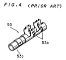
- the spark plug device of Fig. 3 comprises a terminal fixture 53 shown in Fig. 4 which has a crimp-fixing portion 53a crimped and fixed to an end of an ignition cable 51 for electrical connection between the terminal fixture 53 and the ignition cable 51, and a front end portion 53b fitted to a terminal portion of a spark plug body 52 for electrical connection between the spark plug body 52 and the ignition cable 51.
- the connected portion from the ignition cable 51 to the spark plug body 52 is covered with a relatively long tubular plug cap 54 made of synthetic resin.
- a rain cover 55 to be fitted to a plug hole of an engine is mounted on the plug cap 54 at its one end on the ignition cable side, and a rubber cap 56 is mounted on the plug cap 54 at its other end on the spark plug body side.
- the above-mentioned spark plug device has a gap between the outer peripheral surface of the terminal fixture 53 and the inner peripheral surface of the plug cap 54.
- a potential gradient at a surface of the plug cap 54 of synthetic resin is not less than 3 KV/mm, which is prone to corona discharge in the air adjacent the terminal fixture 53, resulting in the likelihood of not only lowering of insulation of the plug cap 54 with degradation thereof by corona discharge but also pin holes due to dielectric breakdown.
- a spark plug device comprises: an ignition cable, a spark plug body having a terminal, a terminal fixture connected to an end of the ignition cable and fitted to the terminal of the spark plug body, a tubular plug cap for covering the spark plug body through to the ignition cable, and a filler material for filling a gap formed between the outer peripheral surface of the terminal fixture and the inner peripheral surface of the plug cap.
- the filler material is used for filling the gap between the outer peripheral surface of the terminal fixture and the inner peripheral surface of the plug cap, there is no layer of air between the terminal fixture and the plug cap to avoid corona discharge. This effectively prevents lowering of insulation of the plug cap with degradation thereof by the corona discharge and the pin holes due to dielectric breakdown.
- the filler material is rubber or an organic material containing neither aluminum nor calcium as an element.
- the filler material made of rubber or the organic material other than rubber which contains neither aluminum nor calcium as an element prevents the production of the deliquescent conductive deposits such as aluminum salt or calcium salt if corona discharge is generated.
- the continuous conduction passageway is prevented which extends from the inner surface to outer surface of the plug cap, and no energy leaks outwardly. Thus, the non-discharge of the spark plug is avoided.
- the filler material includes an insulator for integrally covering the inner peripheral surface of the plug cap.
- the spark plug device further comprises a rubber cap fitted to the plug cap at its one end on the spark plug body side, the filler material being formed of the same material as and integrally with the rubber cap.
- the insulation thickness of the plug cap substantially increases by the presence of the insulative material, whereby the pin holes due to the dielectric breakdown are not liable to be produced.
- the insulative material is rubber, abrasion of the head of the spark plug body and inner surface of the plug cap due to vibration is alleviated.
- the filler material may be either insulative or conductive only for the purpose of preventing corona discharge.
- An object of the present invention is to provide a spark plug device which prevents corona discharge adjacent a terminal fixture and has excellent durability and reliable insulation.
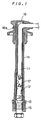
- a terminal fixture 12 is crimped and fixed to an end of an ignition cable 11 for electrical connection between the ignition cable 11 and the terminal fixture 12.
- a front end of the terminal fixture 12 is fitted to a terminal portion of a spark plug body 13 for electrical connection between the ignition cable 11 and the spark plug body 13.
- the ignition cable 11 and spark plug body 13 electrically connected to each other through the terminal fixture 12 are covered with a plug cap 14 of elongated, tubular configuration like the prior art made of synthetic resin such as PBT (polybutylene terephthalate) and UP (unsaturated polyester resin).
- a rubber cap 15 is fitted in and on the plug cap 14 at its one end or lower end.
- a rain cover 16 made of rubber or the like is fitted over the plug cap 14 at its other end or upper end, and an air bent hole 16a is formed exteriorly of the rain cover 16.
- a cylindrical insulating cover 17 made of a fluid material having elasticity if hardened such as silicone rubber is fitted in the inner periphery of the plug cap 14 in a portion corresponding to the terminal fixture 12 to fill the gap external to the terminal fixture 12.
- the insulating cover 17 made of silicone rubber, if containing a metallic element such as aluminum or calcium, produces no conductive deposits such as aluminum salt or calcium salt, thereby preventing outward energy leaks and non-discharge of the spark plug body 13.
- ozone gas (O3) generated by the corona discharge chemically reacts with nitrogen gas (N2) in the air to produce nitrate ions (NO3 ⁇ ), which in turn react with aluminum or calcium in the insulating cover 17 to produce deliquescent Al(NO3)3 or Ca(NO3)2.
- N2 nitrogen gas
- NO3 ⁇ nitrate ions
- a continuous conduction passageway is thus formed which extends from the inner surface to outer surface of the insulating cover 17, resulting in electrical energy leaks.
- the material of the insulating cover 17, if an organic material other than rubber, preferably contains neither aluminum nor calcium.
- the separate insulating cover 17 is fitted in the plug cap 14.
- the inner peripheral surface of the plug cap 14 may be integrally coated with the same insulator. Otherwise, the gap between the terminal fixture 12 and the plug cap 14 may be filled with an insulative material.
- the insulating cover 17 and the rubber cap 15 are separate members in this preferred embodiment, the insulating cover 17 and the rubber cap 15 may be integrally formed of the same material, provided that the material is suited for the insulating cover 17.
Landscapes
- Spark Plugs (AREA)
- Ignition Installations For Internal Combustion Engines (AREA)
- Connector Housings Or Holding Contact Members (AREA)
Applications Claiming Priority (2)
| Application Number | Priority Date | Filing Date | Title |
|---|---|---|---|
| JP103636/93 | 1993-04-05 | ||
| JP10363693A JPH06295756A (ja) | 1993-04-05 | 1993-04-05 | スパークプラグの接続構造 |
Publications (2)
| Publication Number | Publication Date |
|---|---|
| EP0619631A1 true EP0619631A1 (fr) | 1994-10-12 |
| EP0619631B1 EP0619631B1 (fr) | 1997-10-15 |
Family
ID=14359261
Family Applications (1)
| Application Number | Title | Priority Date | Filing Date |
|---|---|---|---|
| EP19940105175 Expired - Lifetime EP0619631B1 (fr) | 1993-04-05 | 1994-03-31 | Arrangement de bougie d'allumage |
Country Status (3)
| Country | Link |
|---|---|
| EP (1) | EP0619631B1 (fr) |
| JP (1) | JPH06295756A (fr) |
| DE (1) | DE69406171T2 (fr) |
Cited By (2)
| Publication number | Priority date | Publication date | Assignee | Title |
|---|---|---|---|---|
| EP0716482A1 (fr) * | 1994-12-07 | 1996-06-12 | Sumitomo Wiring Systems, Ltd. | Appareil d'assemblage de connecteur de bougie |
| EP0793319A1 (fr) * | 1996-02-29 | 1997-09-03 | General Motors Corporation | Capuchon isolateur pour bougie d'allumage |
Families Citing this family (2)
| Publication number | Priority date | Publication date | Assignee | Title |
|---|---|---|---|---|
| JP5362486B2 (ja) * | 2009-08-27 | 2013-12-11 | ダイニチ工業株式会社 | 燃焼装置 |
| TWI631276B (zh) * | 2017-10-31 | 2018-08-01 | 電子設計天地貿易責任有限公司 | 汽車點火裝置與點火加速器 |
Citations (3)
| Publication number | Priority date | Publication date | Assignee | Title |
|---|---|---|---|---|
| US2458121A (en) * | 1945-06-23 | 1949-01-04 | Bendix Aviat Corp | Radio shielded ignition means |
| US3914003A (en) * | 1972-12-14 | 1975-10-21 | Kabel Metallwerke Ghh | Spark plug socket for internal combustion engines |
| EP0383661A1 (fr) * | 1989-02-14 | 1990-08-22 | Societe D'application Des Ferrites-Musorb | Dispositif de connexion électrique d'un câble, notamment d'allumage, sur un plot |
-
1993
- 1993-04-05 JP JP10363693A patent/JPH06295756A/ja active Pending
-
1994
- 1994-03-31 EP EP19940105175 patent/EP0619631B1/fr not_active Expired - Lifetime
- 1994-03-31 DE DE1994606171 patent/DE69406171T2/de not_active Expired - Fee Related
Patent Citations (3)
| Publication number | Priority date | Publication date | Assignee | Title |
|---|---|---|---|---|
| US2458121A (en) * | 1945-06-23 | 1949-01-04 | Bendix Aviat Corp | Radio shielded ignition means |
| US3914003A (en) * | 1972-12-14 | 1975-10-21 | Kabel Metallwerke Ghh | Spark plug socket for internal combustion engines |
| EP0383661A1 (fr) * | 1989-02-14 | 1990-08-22 | Societe D'application Des Ferrites-Musorb | Dispositif de connexion électrique d'un câble, notamment d'allumage, sur un plot |
Cited By (4)
| Publication number | Priority date | Publication date | Assignee | Title |
|---|---|---|---|---|
| EP0716482A1 (fr) * | 1994-12-07 | 1996-06-12 | Sumitomo Wiring Systems, Ltd. | Appareil d'assemblage de connecteur de bougie |
| US5706569A (en) * | 1994-12-07 | 1998-01-13 | Sumitomo Wiring Systems, Ltd. | Apparatus for assembling plug joint |
| EP0793319A1 (fr) * | 1996-02-29 | 1997-09-03 | General Motors Corporation | Capuchon isolateur pour bougie d'allumage |
| US5716223A (en) * | 1996-02-29 | 1998-02-10 | General Motors Corporation | Spark plug boot insulator |
Also Published As
| Publication number | Publication date |
|---|---|
| JPH06295756A (ja) | 1994-10-21 |
| DE69406171T2 (de) | 1998-03-05 |
| EP0619631B1 (fr) | 1997-10-15 |
| DE69406171D1 (de) | 1997-11-20 |
Similar Documents
| Publication | Publication Date | Title |
|---|---|---|
| CN1046570C (zh) | 用于内燃机的连接火花塞和点火线圈的结构 | |
| US6111345A (en) | Spark plug for apparatus for detecting ion current without generating spike-like noise on the ion current | |
| EP0142928B1 (fr) | Capuchon pour bougie d'allumage | |
| US3076113A (en) | Spark plug and connector device therefor | |
| US3128139A (en) | Spark plug shield | |
| US2690541A (en) | Waterproof connection for spark plug terminals and the like | |
| JP2780964B2 (ja) | コイル及びスパークプラグの組立体 | |
| CA2056830C (fr) | Dispositif a cable a haute tension | |
| EP0619631A1 (fr) | Arrangement de bougie d'allumage | |
| US6358072B1 (en) | Aircraft ignition cable connector | |
| EP0407976B1 (fr) | Dispositif de décharge et système d'allumage, comprenant un éclateur en série utilisant le dispositif de décharge | |
| JP4193975B2 (ja) | 気密端子ユニット | |
| US5679011A (en) | Spark plug device | |
| EP0534176B1 (fr) | Disposition de connexion d'un fil de résistance à haute tension | |
| US5028747A (en) | Distributor cap | |
| US2296054A (en) | Shield for spark plugs | |
| US3941107A (en) | Ignition distributor rotor | |
| US6932627B2 (en) | Connecting device for ignition systems of internal combustion engines | |
| EP0109836B1 (fr) | Isolateur | |
| US3431534A (en) | Secondary ignition wire end assembly | |
| JPH0233473A (ja) | 点火コイルのプラグキャップ | |
| US3315206A (en) | Radiation suppressor for internal combustion engine ignition system | |
| JP3149209B2 (ja) | プラグキャップ装置 | |
| EP0635918A2 (fr) | Dispositif à décharge et système d'allumage à intervalle en série utilisant un dispositif à décharge | |
| US5276283A (en) | Distributor cap |
Legal Events
| Date | Code | Title | Description |
|---|---|---|---|
| PUAI | Public reference made under article 153(3) epc to a published international application that has entered the european phase |
Free format text: ORIGINAL CODE: 0009012 |
|
| AK | Designated contracting states |
Kind code of ref document: A1 Designated state(s): DE FR GB |
|
| 17P | Request for examination filed |
Effective date: 19940825 |
|
| 17Q | First examination report despatched |
Effective date: 19950726 |
|
| GRAG | Despatch of communication of intention to grant |
Free format text: ORIGINAL CODE: EPIDOS AGRA |
|
| GRAH | Despatch of communication of intention to grant a patent |
Free format text: ORIGINAL CODE: EPIDOS IGRA |
|
| GRAH | Despatch of communication of intention to grant a patent |
Free format text: ORIGINAL CODE: EPIDOS IGRA |
|
| GRAA | (expected) grant |
Free format text: ORIGINAL CODE: 0009210 |
|
| AK | Designated contracting states |
Kind code of ref document: B1 Designated state(s): DE FR GB |
|
| REF | Corresponds to: |
Ref document number: 69406171 Country of ref document: DE Date of ref document: 19971120 |
|
| ET | Fr: translation filed | ||
| PLBE | No opposition filed within time limit |
Free format text: ORIGINAL CODE: 0009261 |
|
| STAA | Information on the status of an ep patent application or granted ep patent |
Free format text: STATUS: NO OPPOSITION FILED WITHIN TIME LIMIT |
|
| 26N | No opposition filed | ||
| PGFP | Annual fee paid to national office [announced via postgrant information from national office to epo] |
Ref country code: FR Payment date: 20000310 Year of fee payment: 7 |
|
| PGFP | Annual fee paid to national office [announced via postgrant information from national office to epo] |
Ref country code: DE Payment date: 20000327 Year of fee payment: 7 |
|
| PGFP | Annual fee paid to national office [announced via postgrant information from national office to epo] |
Ref country code: GB Payment date: 20000329 Year of fee payment: 7 |
|
| PG25 | Lapsed in a contracting state [announced via postgrant information from national office to epo] |
Ref country code: GB Free format text: LAPSE BECAUSE OF NON-PAYMENT OF DUE FEES Effective date: 20010331 |
|
| GBPC | Gb: european patent ceased through non-payment of renewal fee |
Effective date: 20010331 |
|
| PG25 | Lapsed in a contracting state [announced via postgrant information from national office to epo] |
Ref country code: FR Free format text: LAPSE BECAUSE OF NON-PAYMENT OF DUE FEES Effective date: 20011130 |
|
| REG | Reference to a national code |
Ref country code: FR Ref legal event code: ST |
|
| PG25 | Lapsed in a contracting state [announced via postgrant information from national office to epo] |
Ref country code: DE Free format text: LAPSE BECAUSE OF NON-PAYMENT OF DUE FEES Effective date: 20020101 |