EP0619633B1 - Procédé de pose d'un produit de grande longueur dans le sol, et dispositifs pour sa mise en oeuvre - Google Patents
Procédé de pose d'un produit de grande longueur dans le sol, et dispositifs pour sa mise en oeuvre Download PDFInfo
- Publication number
- EP0619633B1 EP0619633B1 EP94400758A EP94400758A EP0619633B1 EP 0619633 B1 EP0619633 B1 EP 0619633B1 EP 94400758 A EP94400758 A EP 94400758A EP 94400758 A EP94400758 A EP 94400758A EP 0619633 B1 EP0619633 B1 EP 0619633B1
- Authority
- EP
- European Patent Office
- Prior art keywords
- tube
- product
- yoke
- core
- ground
- Prior art date
- Legal status (The legal status is an assumption and is not a legal conclusion. Google has not performed a legal analysis and makes no representation as to the accuracy of the status listed.)
- Expired - Lifetime
Links
- 238000000034 method Methods 0.000 title claims description 6
- 230000005291 magnetic effect Effects 0.000 claims description 32
- 239000003302 ferromagnetic material Substances 0.000 claims description 2
- 230000001681 protective effect Effects 0.000 claims 1
- 238000011144 upstream manufacturing Methods 0.000 claims 1
- 239000002689 soil Substances 0.000 description 5
- 238000004804 winding Methods 0.000 description 5
- 238000013467 fragmentation Methods 0.000 description 4
- 238000006062 fragmentation reaction Methods 0.000 description 4
- 238000009933 burial Methods 0.000 description 3
- XEEYBQQBJWHFJM-UHFFFAOYSA-N Iron Chemical compound [Fe] XEEYBQQBJWHFJM-UHFFFAOYSA-N 0.000 description 2
- 238000009412 basement excavation Methods 0.000 description 2
- 238000006073 displacement reaction Methods 0.000 description 2
- 239000000463 material Substances 0.000 description 2
- ZOXJGFHDIHLPTG-UHFFFAOYSA-N Boron Chemical compound [B] ZOXJGFHDIHLPTG-UHFFFAOYSA-N 0.000 description 1
- 229910052779 Neodymium Inorganic materials 0.000 description 1
- 229910052796 boron Inorganic materials 0.000 description 1
- 238000000151 deposition Methods 0.000 description 1
- 230000000694 effects Effects 0.000 description 1
- 230000005611 electricity Effects 0.000 description 1
- 239000012634 fragment Substances 0.000 description 1
- 229920001903 high density polyethylene Polymers 0.000 description 1
- 239000004700 high-density polyethylene Substances 0.000 description 1
- 238000003780 insertion Methods 0.000 description 1
- 230000037431 insertion Effects 0.000 description 1
- 238000009434 installation Methods 0.000 description 1
- 229910052742 iron Inorganic materials 0.000 description 1
- 230000001050 lubricating effect Effects 0.000 description 1
- 239000000696 magnetic material Substances 0.000 description 1
- QEFYFXOXNSNQGX-UHFFFAOYSA-N neodymium atom Chemical compound [Nd] QEFYFXOXNSNQGX-UHFFFAOYSA-N 0.000 description 1
- 230000002093 peripheral effect Effects 0.000 description 1
- 229920001296 polysiloxane Polymers 0.000 description 1
- 239000011435 rock Substances 0.000 description 1
Images
Classifications
-
- H—ELECTRICITY
- H02—GENERATION; CONVERSION OR DISTRIBUTION OF ELECTRIC POWER
- H02G—INSTALLATION OF ELECTRIC CABLES OR LINES, OR OF COMBINED OPTICAL AND ELECTRIC CABLES OR LINES
- H02G1/00—Methods or apparatus specially adapted for installing, maintaining, repairing or dismantling electric cables or lines
- H02G1/06—Methods or apparatus specially adapted for installing, maintaining, repairing or dismantling electric cables or lines for laying cables, e.g. laying apparatus on vehicle
- H02G1/08—Methods or apparatus specially adapted for installing, maintaining, repairing or dismantling electric cables or lines for laying cables, e.g. laying apparatus on vehicle through tubing or conduit, e.g. rod or draw wire for pushing or pulling
-
- E—FIXED CONSTRUCTIONS
- E02—HYDRAULIC ENGINEERING; FOUNDATIONS; SOIL SHIFTING
- E02F—DREDGING; SOIL-SHIFTING
- E02F5/00—Dredgers or soil-shifting machines for special purposes
- E02F5/02—Dredgers or soil-shifting machines for special purposes for digging trenches or ditches
- E02F5/10—Dredgers or soil-shifting machines for special purposes for digging trenches or ditches with arrangements for reinforcing trenches or ditches; with arrangements for making or assembling conduits or for laying conduits or cables
- E02F5/102—Dredgers or soil-shifting machines for special purposes for digging trenches or ditches with arrangements for reinforcing trenches or ditches; with arrangements for making or assembling conduits or for laying conduits or cables operatively associated with mole-ploughs, coulters
- E02F5/103—Dredgers or soil-shifting machines for special purposes for digging trenches or ditches with arrangements for reinforcing trenches or ditches; with arrangements for making or assembling conduits or for laying conduits or cables operatively associated with mole-ploughs, coulters with oscillating or vibrating digging tools
-
- H—ELECTRICITY
- H02—GENERATION; CONVERSION OR DISTRIBUTION OF ELECTRIC POWER
- H02G—INSTALLATION OF ELECTRIC CABLES OR LINES, OR OF COMBINED OPTICAL AND ELECTRIC CABLES OR LINES
- H02G1/00—Methods or apparatus specially adapted for installing, maintaining, repairing or dismantling electric cables or lines
- H02G1/06—Methods or apparatus specially adapted for installing, maintaining, repairing or dismantling electric cables or lines for laying cables, e.g. laying apparatus on vehicle
Definitions
- the invention relates to a method for installing a long product in the ground, such as a cable or a tubular product, the preferred applications being first burial of telecommunications cables and secondly the burial of electric cables from power.
- the soil fragmentation process along a groove while depositing in said groove, as and as it is made, a length of one tube suitable for accommodating said product with play consists according to the invention, as the tube is laid in the groove to pull the product by its free end in the same direction as that of laying the tube inside this by means of a magnetic drive device comprising a tubular cylinder head capable of being traversed with clearance through the tube and a cylindrical core capable of being accommodated with clearance in the tube, the cylinder head and the core comprising magnetic means arranged to produce a magnetic field radial between them and through said tube, suitable for axially immobilize the core relative to the cylinder head, said product end being fixed to said core, the pulling on the product by moving said product breech parallel to the groove as execution of it.
- a magnetic drive device comprising a tubular cylinder head capable of being traversed with clearance through the tube and a cylindrical core capable of being accommodated with clearance in the tube, the cylinder head and the core comprising magnetic means arranged to produce a magnetic field
- the first aforementioned problem is solved by the fact that the tube and the product are placed simultaneously in the same operation, rather than two operations successive according to which the tube would first be deposited, then we would draw the product into the tube on a large length by means of a rope or "cable".
- the invention also relates to a laying device a product of great length in the ground, allowing implement the above method, as well as a device magnetic drive to pull such a product in a tube.
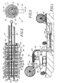
- FIG. 1 a subsoiler 1 consisting of a tractor mounted on tracks, at the rear which is attached a vibrating coulter 2.
- the vibrating coulter is in general L shape including 3 post and base transverse 4, one end of the base near the upright bearing a point forming a share 5.
- the upright 3 and the base 4 are crossed longitudinally by a cylindrical cavity 6 of circular section extending, in a connection zone between the upright 3 and the base 4, at an elbow 7.
- the arrangement is such that the base 4 of the share 2 is arranged under the surface 10 of the ground.
- the subsoiler 1 carries, in a front region, a tube drum 11 rotatably supported on two arms 12 and on which a tube 13 is wound.
- the tube drum 11 includes means not shown to brake its rotation.
- the tube 13 is made of a semi-rigid non-magnetic material having sufficient flexibility to allow its winding on the tube reel 11, for example in high density polyethylene.
- the tube 13 internally carries a lubricating layer such as layer of silicone or a film of oil.
- Subsoiler 1 still wears, in a region intermediate between the tube reel 11 and the ploughshare 2, a magnetic drive 14 comprising a central core 15 and a peripheral cylinder head 16 receiving the latter.
- the breech 16 comprises a cylinder 17 of circular section having an inner rim 20 at one end and carrying a foot 21 in the form of a rectangular plate extending over a part of the length of cylinder 17 and connecting a surface outside of it to the subsoiler 1.
- the cylinder 17 is fixed so as to extend parallel to the direction displacement of the subsoiler 1 and to face a portion of tube 13 as delivered by the drum tube 11.
- pole pieces 24, 25 magnetized by permanent magnets 23 to constitute a succession of north poles 24 and south poles 25.
- These magnets and poles are are in the form of circular crowns, the outer diameter roughly corresponds to the diameter inside of cylinder 17.
- the north 24 and south 25 poles are arranged alternately along cylinder 17 and separated from each other by magnets 23 so that each magnet 23 is interposed between a north pole 24 and a pole south 25, each pole being double in the sense that it constitutes a pole piece of the same sign for the two magnets between which it is found.
- an annular nut 30 which cooperates with the surface inside of the cylinder so as to compress against each other the others the magnets 23 and the poles 24 to 27.
- the core 15 of the magnetic drive 14 is formed by a stack of magnets 31, north poles 32 and south poles 33 in the form of discs identical in thickness to that of the crowns fitted to the cylinder head 16, arranged alternately along the core of the same way as the crowns, the number of discs being equal to that of crowns.
- this mutual position of the cylinder head 16 and of the core 15 corresponds to a position of the magnetic trainer in which it there is a purely radial magnetic field extending between the poles of the cylinder head 16 and those of the core 15, the core therefore not subject to any tensile force axial.
- Discs 31 to 33 are crossed centrally by a threaded rod 34 and compressed against each other others on it by means of two nuts 35 located on either side of the disk assembly.
- the rod threaded 34 extends beyond it on some length and carries, at its end, a ring 36.
- the tube 13 passes through the cylinder head 16, surrounding the core 15.
- the respective diameters of these parts are such there is only a slight radial clearance between the tube 13 and the cylinder head 16 on the one hand, and between this tube and the core on the other hand, chosen to allow relative displacement of these pieces relative to each other.
- the material of the magnets and the number of these are chosen so that the core 15 can withstand an axial tensile force of the order of 200 to 300 daN.
- a number of pairs of north-south poles equal to twenty, corresponding to a magnetic drive length of 1 m approximately, allowed to obtain a resistance of 260 daN.
- the poles 24, 25, 32, 33 of the cylinder head 16 and of the core 15 are made of a soft ferromagnetic material.
- cylinder 17 of cylinder head 16 it is made of a material non-magnetic.
- a cable 40 such than a telecommunications cable or an electrical cable of power
- a cable reel 41 comprising support means 42 for placing it on the ground 10.
- This is for example a cable with a diameter of 14 mm, to which is associated with a tube with an outside diameter of 50 mm.
- the free end of the tube 13 between the breech 16 and the core 15 of the coach magnetic This can be done in practice in various ways.
- fingers of retractable centering may be provided inside the breech to maintain the core coaxial with the breech, before inserting the tube.
- the cylinder head may be designed as two semi-cylindrical half-shells which will be reported around the tube and assembled to each other, after insertion of the core into the tube.
- the free end of the tube 13 is then inserted inside the vibrating share 2, from the free end of the amount 3 thereof, producing a curvature 44 of the tube between the magnetic drive and the vibrating share. Once the free end of the tube 13 is emerged slightly from the base 4 of the vibrating share 2, the cable burial operation can begin.
- the subsoiler 1 advances so that the point 5 of the vibrating share fragments the ground, and the fact that the part of tube 13 already buried is immobilized in the ground, there is a traction on the tube 13 which moves it towards the magnetic drive 14 according to the arrow 45 then towards the vibrating share 2 to finally rest horizontally in the basement.
- the subsoiler 1 performs a pull in its advance movement on cable 40 according to arrow 46, which has the effect of dispose, for each unit length of buried tube 13, a corresponding length of cable inside this one.
- the invention does not require no need to unwind the entire length of tube and cable disposed on the tube reel 11 and the cable reel 41 respectively, when passing the singular point, which provides significant operating time savings.
- each crown 23 to 27 or disc 31 to 33 may be replaced by a group of discrete elements, juxtaposed and arranged peripherally around the axis of the coach magnetic 14.
- the magnetic trainer may be of the electromagnetic type, that is to say designed according to the principle of an electromagnet and include windings of conductive wires, either connected to a source of electrical energy in the case of windings carried by the cylinder head, or not connected to such a source if it is of windings carried by the core.
- the magnetic drive may include both windings of conductive wires supplied with electricity and permanent magnets.
- the tube 13 could have any section of appropriate shape, different from shape circular mentioned above.
- the means of tube guide 13 in the ground are in one piece with the means of soil fragmentation and occur under the shape of the hollow vibrating share 2, these means can be physically distinct from each other: thus, the means of soil fragmentation may consist of a rock saw placed in front of the tube guide means, the latter appearing in the same general form of L than the vibrating share 2.
Landscapes
- Engineering & Computer Science (AREA)
- Mechanical Engineering (AREA)
- Mining & Mineral Resources (AREA)
- Civil Engineering (AREA)
- General Engineering & Computer Science (AREA)
- Structural Engineering (AREA)
- Catching Or Destruction (AREA)
- Geophysics And Detection Of Objects (AREA)
- Hard Magnetic Materials (AREA)
- Warehouses Or Storage Devices (AREA)
- Storing, Repeated Paying-Out, And Re-Storing Of Elongated Articles (AREA)
- Magnetic Treatment Devices (AREA)
- Excavating Of Shafts Or Tunnels (AREA)
- Soil Working Implements (AREA)
Description
Claims (5)
- Procédé de pose dans le sol d'un produit de grande longueur simultanément à la pose d'un tube de protection destiné à entourer ledit produit, selon lequel on fragmente le sol selon un sillon tout en déposant dans ledit sillon, au fur et à mesure de la réalisation de celui-ci, une longueur d'un tube (13) apte à loger ledit produit (40) avec jeu, caractérisé en ce que au fur et à mesure de la pose dudit tube (13) dans le sillon, on tire par son extrémité libre le produit dans le même sens que celui de la pose du tube et à l'intérieur de celui-ci au moyen d'un dispositif d'entraínement magnétique (14) comprenant une culasse tubulaire (16) apte à être traversée avec jeu par le tube (13) et un noyau cylindrique (15) apte à être logé avec jeu dans le tube, la culasse et le noyau comportant des moyens magnétiques (23 à 27 ; 31 à 33) agencés pour produire un champ magnétique radial entre eux et au travers dudit tube (13), propre à immobiliser axialement le noyau (15) par rapport à la culasse (16), ladite extrémité de produit étant fixée audit noyau, la traction sur le produit s'effectuant en déplaçant ladite culasse (16) parallèlement au sillon au fur et à mesure de l'exécution de celui-ci.
- Dispositif de pose dans le sol d'un produit de grande longueur (40) disposé dans un tube (13), comportant une sous-soleuse (1) sur laquelle sont montés des moyens de fragmentation (5) agencés pour fragmenter le sol selon un sillon à une profondeur correspondant à la profondeur de pose du produit et un touret de tube (11) apte à délivrer une longueur de tube sensiblement égale à celle du produit à poser ; caractérisé en ce que sur la sous-soleuse sont montés un dispositif d'entraínement magnétique pour tirer le produit (40) à l'intérieur du tube (13), disposé entre le touret de tube (11) et les moyens de fragmentation (5) et comprenant une culasse tubulaire (16) apte à être traversée avec jeu par le tube (13) et un noyau cylindrique (15) apte à être logé avec jeu dans le tube, la culasse et le noyau comportant des moyens magnétiques (23 à 27 ; 31 à 33) agencés pour produire un champ magnétique radial entre eux et au travers dudit tube, propre à immobiliser axialement le noyau (15) par rapport à la culasse (16), la culasse étant fixée sur la sous-soleuse et le noyau comprenant des moyens pour permettre la fixation d'une extrémité du produit sur lui.
- Dispositif de pose selon la revendication 2, dans lequel le produit (40) est enroulé sur un touret de produit (41) équipé de moyens de support (42) par lesquels celui-ci repose sur le sol en amont dudit sillon.
- Dispositif de pose selon la revendication 2 caractérisé en ce que lesdits moyens magnétiques comprennent, sur la culasse (16) et sur le noyau (15), une pluralité de pièces polaires (24, 25 ; 32, 33) en un matériau ferromagnétique, juxtaposées le long d'un axe longitudinal de la culasse, chaque pièce polaire étant séparée des pièces polaires adjacentes par un aimant permanent (23 ; 31).
- Dispositif selon la revendication 4, dans lequel lesdits aimants (23) et pièces polaires (24, 25) portés par la culasse sont en forme de couronne, tandis que ceux (31 à 33) portés par le noyau sont en forme de disque d'épaisseur semblable à celle de ladite couronne, les couronnes et les disques s'étendant perpendiculairement à l'axe longitudinal de la culasse.
Applications Claiming Priority (2)
| Application Number | Priority Date | Filing Date | Title |
|---|---|---|---|
| FR9304183A FR2703707B1 (fr) | 1993-04-08 | 1993-04-08 | Procédé de pose d'un produit de grande longueur dans le sol, et dispositifs pour sa mise en Óoeuvre. |
| FR9304183 | 1993-04-08 |
Publications (2)
| Publication Number | Publication Date |
|---|---|
| EP0619633A1 EP0619633A1 (fr) | 1994-10-12 |
| EP0619633B1 true EP0619633B1 (fr) | 1998-01-14 |
Family
ID=9445891
Family Applications (1)
| Application Number | Title | Priority Date | Filing Date |
|---|---|---|---|
| EP94400758A Expired - Lifetime EP0619633B1 (fr) | 1993-04-08 | 1994-04-07 | Procédé de pose d'un produit de grande longueur dans le sol, et dispositifs pour sa mise en oeuvre |
Country Status (9)
| Country | Link |
|---|---|
| US (1) | US5464308A (fr) |
| EP (1) | EP0619633B1 (fr) |
| AU (1) | AU677629B2 (fr) |
| BR (1) | BR9400958A (fr) |
| CA (1) | CA2120802C (fr) |
| DE (1) | DE69407851T2 (fr) |
| ES (1) | ES2112494T3 (fr) |
| FR (1) | FR2703707B1 (fr) |
| NZ (1) | NZ260264A (fr) |
Families Citing this family (13)
| Publication number | Priority date | Publication date | Assignee | Title |
|---|---|---|---|---|
| GB2337095B (en) * | 1996-03-04 | 2000-05-03 | British Gas Plc | Pipe clamp |
| US5741088A (en) * | 1996-08-23 | 1998-04-21 | Environment 2000, Inc. | Apparatus for underground excavation |
| US20030108391A1 (en) * | 2001-12-12 | 2003-06-12 | Lee Essay | Passive irrigation pipe installation reel stand |
| DK1357252T3 (da) * | 2002-04-15 | 2006-05-15 | Koninkl Kpn Nv | Fremgangsmåde og anordning til installation af en kanal rundt om et eksisterende langsgående element |
| US7403643B2 (en) * | 2006-08-11 | 2008-07-22 | Fotonation Vision Limited | Real-time face tracking in a digital image acquisition device |
| CN100440660C (zh) * | 2006-12-25 | 2008-12-03 | 山东铝业工程有限公司 | 超长大截面电缆的机械敷设方法 |
| CN103779800B (zh) * | 2014-01-18 | 2016-03-30 | 安徽华茜电缆科技有限公司 | 一种电力线缆自动放料设备 |
| CA3006920C (fr) | 2017-06-01 | 2023-05-23 | Precise Downhole Services Ltd. | Transport sans liquide de cable de fibre optique |
| CA3101392A1 (en) | 2019-12-03 | 2021-06-03 | Precise Downhole Services Ltd. | High density thermistor cable |
| CN112060009A (zh) * | 2020-09-10 | 2020-12-11 | 岳阳高澜节能装备制造有限公司 | 一种线缆穿管工装 |
| CN113036662B (zh) * | 2021-03-11 | 2021-10-26 | 湖南天禹设备安装有限公司 | 一种高层竖井电缆导向施工用限位、导向装置 |
| CN113266050A (zh) * | 2021-06-15 | 2021-08-17 | 俞晓辉 | 一种配合挖掘机使用的通信线缆用埋管装置 |
| CN115823346A (zh) * | 2022-11-21 | 2023-03-21 | 江苏高升特种管业有限公司 | 柔性复合管智能化敷设装备 |
Citations (2)
| Publication number | Priority date | Publication date | Assignee | Title |
|---|---|---|---|---|
| US1904666A (en) * | 1930-04-09 | 1933-04-18 | Sack Hans | Apparatus for laying drain pipes or cables |
| US4896997A (en) * | 1985-09-27 | 1990-01-30 | Gaylin Wayne L | Cable sheathing and burying method |
Family Cites Families (6)
| Publication number | Priority date | Publication date | Assignee | Title |
|---|---|---|---|---|
| FI28487A (fi) * | 1956-07-10 | Kaitera P Liukko T Tuomola A | Menettelytapa ja laite mukaanottoelimien kuljettamiseksi pitkissä letkuissa | |
| US3390533A (en) * | 1964-10-01 | 1968-07-02 | Diggers Inc | Machine for laying cable and the like |
| LU81062A1 (fr) * | 1979-03-19 | 1980-10-08 | Ruidant M | Perfectionnements aux installations de cables ou lignes electriques |
| JPS5729013A (en) * | 1980-07-30 | 1982-02-16 | Fujikura Ltd | Method for drawing optical fiber into nonmagnetic metallic pipe |
| JPS5876804U (ja) * | 1981-11-19 | 1983-05-24 | 焼結金属工業株式会社 | ロツドレスシリンダ |
| DE3521566A1 (de) * | 1985-06-15 | 1986-12-18 | Josef Schnell KG Holz- und Bautenschutz, 7570 Baden-Baden | Vorrichtung zum einsanden eines oder mehrerer kabel bzw. rohre waehrend des einpfluegens in den boden mittels eines kabelverlegepfluges |
-
1993
- 1993-04-08 FR FR9304183A patent/FR2703707B1/fr not_active Expired - Fee Related
-
1994
- 1994-04-07 EP EP94400758A patent/EP0619633B1/fr not_active Expired - Lifetime
- 1994-04-07 CA CA002120802A patent/CA2120802C/fr not_active Expired - Lifetime
- 1994-04-07 DE DE69407851T patent/DE69407851T2/de not_active Expired - Lifetime
- 1994-04-07 US US08/224,168 patent/US5464308A/en not_active Expired - Lifetime
- 1994-04-07 ES ES94400758T patent/ES2112494T3/es not_active Expired - Lifetime
- 1994-04-07 NZ NZ260264A patent/NZ260264A/en not_active IP Right Cessation
- 1994-04-08 AU AU59374/94A patent/AU677629B2/en not_active Expired
- 1994-04-08 BR BR9400958A patent/BR9400958A/pt not_active IP Right Cessation
Patent Citations (2)
| Publication number | Priority date | Publication date | Assignee | Title |
|---|---|---|---|---|
| US1904666A (en) * | 1930-04-09 | 1933-04-18 | Sack Hans | Apparatus for laying drain pipes or cables |
| US4896997A (en) * | 1985-09-27 | 1990-01-30 | Gaylin Wayne L | Cable sheathing and burying method |
Also Published As
| Publication number | Publication date |
|---|---|
| FR2703707A1 (fr) | 1994-10-14 |
| US5464308A (en) | 1995-11-07 |
| EP0619633A1 (fr) | 1994-10-12 |
| DE69407851T2 (de) | 1998-07-30 |
| FR2703707B1 (fr) | 1995-09-29 |
| AU5937494A (en) | 1994-10-13 |
| DE69407851D1 (de) | 1998-02-19 |
| BR9400958A (pt) | 1995-03-07 |
| AU677629B2 (en) | 1997-05-01 |
| CA2120802C (fr) | 1998-01-06 |
| NZ260264A (en) | 1995-07-26 |
| ES2112494T3 (es) | 1998-04-01 |
| CA2120802A1 (fr) | 1994-10-09 |
Similar Documents
| Publication | Publication Date | Title |
|---|---|---|
| EP0619633B1 (fr) | Procédé de pose d'un produit de grande longueur dans le sol, et dispositifs pour sa mise en oeuvre | |
| EP1224719B1 (fr) | Dispositif de guidage d'au moins un element longiligne souple, tel que cable ou autre, a contour substantiellement ferme | |
| FR2763635A1 (fr) | Appareil et procede pour assurer un support a un cable elec- trique s'etendant dans un tube pour puits, notamment pour transmettre de la puissance a une pompe submersible | |
| FR2660790A1 (fr) | Cable profile pour mise en place dans une conduite de grande longueur. | |
| FR2595114A1 (fr) | Procede et dispositif pour guider un tuyau souple de distribution de beton lors d'un renforcement de roche par fils metalliques noyes dans du beton | |
| EP0687048B1 (fr) | Procédé et dispositif de pose d'un câble souterrain de télécommunications | |
| EP2425697B1 (fr) | Ensemble de rouleau pour machines agricoles | |
| BE1007542A3 (fr) | Dispositif et procede pour extraire du terrain sans le casser un branchement d'adduction d'eau en plomb et le remplacer dans le meme temps par un branchement en matiere plastique. | |
| FR2516024A1 (fr) | Dispositif de prise de force pour vehicule a roues sans-moteur | |
| EP2327833B1 (fr) | Dispositif pour protéger au moins un objet de forme générale allongée tel qu'un câble ou une conduite | |
| CA2474081C (fr) | Procede d'installation d'un cable de fortes ou moyennes puissances dans le sol | |
| WO2005083724A1 (fr) | Ruban souple de transfert d’energie | |
| FR2723780A1 (fr) | Procede de remplacement de canalisations en plomb sans realisation de tranchees, et appareillages de mise en oeuvre | |
| EP1715554A2 (fr) | Procédé, et dispositif portatif, pour le pré-filage d'une gaine | |
| EP0775798B1 (fr) | Dispositif d'entraínement en rotation d'un élément d'enroulement de volet roulant | |
| FR2462863A1 (fr) | Mecanisme de moulinet de peche pour compensation de l'effet de recuperation de la ligne par rapport a la force de freinage lors de l'extraction de la ligne | |
| FR2559316A1 (fr) | Appareil destine a se deplacer le long d'un cable enterre | |
| FR3150051A3 (fr) | Tire-câble | |
| FR2578930A1 (fr) | Dispositif a translation pour freiner le defilement d'un element allonge tel qu'un tuyau ou un cable | |
| FR2667759A1 (fr) | Dispositif, engin et procede de recuperation d'une nappe de film ou filet. | |
| FR2716751A1 (fr) | Procédé et dispositif pour la pose d'une ligne de transport à isolation gazeuse. | |
| FR2826426A1 (fr) | Procede pour poser, dans une tranchee, au moins un objet allonge, unite mobile pour mettre en oeuvre ledit procede et element prefabrique a poser, avec ledit objet allonge, dans ladite tranchee | |
| FR2708393A1 (fr) | Conduit de protection à friction réduite. | |
| FR2734421A1 (fr) | Procede et dispositif pour la mise en place de cables de telecommunications a l'interieur d'une conduite contenant deja un cable existant | |
| EP4475144A1 (fr) | Installation et procédé de déroulement, protection et ré-enroulement d'un objet de type canalisation |
Legal Events
| Date | Code | Title | Description |
|---|---|---|---|
| PUAI | Public reference made under article 153(3) epc to a published international application that has entered the european phase |
Free format text: ORIGINAL CODE: 0009012 |
|
| AK | Designated contracting states |
Kind code of ref document: A1 Designated state(s): DE ES FR GB IT |
|
| 17P | Request for examination filed |
Effective date: 19950320 |
|
| 17Q | First examination report despatched |
Effective date: 19960919 |
|
| GRAG | Despatch of communication of intention to grant |
Free format text: ORIGINAL CODE: EPIDOS AGRA |
|
| GRAG | Despatch of communication of intention to grant |
Free format text: ORIGINAL CODE: EPIDOS AGRA |
|
| GRAH | Despatch of communication of intention to grant a patent |
Free format text: ORIGINAL CODE: EPIDOS IGRA |
|
| GRAH | Despatch of communication of intention to grant a patent |
Free format text: ORIGINAL CODE: EPIDOS IGRA |
|
| GRAA | (expected) grant |
Free format text: ORIGINAL CODE: 0009210 |
|
| AK | Designated contracting states |
Kind code of ref document: B1 Designated state(s): DE ES FR GB IT |
|
| REF | Corresponds to: |
Ref document number: 69407851 Country of ref document: DE Date of ref document: 19980219 |
|
| REG | Reference to a national code |
Ref country code: ES Ref legal event code: FG2A Ref document number: 2112494 Country of ref document: ES Kind code of ref document: T3 |
|
| ITF | It: translation for a ep patent filed | ||
| GBT | Gb: translation of ep patent filed (gb section 77(6)(a)/1977) |
Effective date: 19980402 |
|
| PLBE | No opposition filed within time limit |
Free format text: ORIGINAL CODE: 0009261 |
|
| STAA | Information on the status of an ep patent application or granted ep patent |
Free format text: STATUS: NO OPPOSITION FILED WITHIN TIME LIMIT |
|
| 26N | No opposition filed | ||
| REG | Reference to a national code |
Ref country code: GB Ref legal event code: IF02 |
|
| REG | Reference to a national code |
Ref country code: GB Ref legal event code: 732E |
|
| REG | Reference to a national code |
Ref country code: GB Ref legal event code: 732E |
|
| PGFP | Annual fee paid to national office [announced via postgrant information from national office to epo] |
Ref country code: ES Payment date: 20120426 Year of fee payment: 19 |
|
| PGFP | Annual fee paid to national office [announced via postgrant information from national office to epo] |
Ref country code: DE Payment date: 20130429 Year of fee payment: 20 Ref country code: GB Payment date: 20130429 Year of fee payment: 20 |
|
| PGFP | Annual fee paid to national office [announced via postgrant information from national office to epo] |
Ref country code: FR Payment date: 20130506 Year of fee payment: 20 Ref country code: IT Payment date: 20130422 Year of fee payment: 20 |
|
| REG | Reference to a national code |
Ref country code: DE Ref legal event code: R071 Ref document number: 69407851 Country of ref document: DE |
|
| REG | Reference to a national code |
Ref country code: GB Ref legal event code: PE20 Expiry date: 20140406 |
|
| REG | Reference to a national code |
Ref country code: ES Ref legal event code: FD2A Effective date: 20140613 |
|
| PG25 | Lapsed in a contracting state [announced via postgrant information from national office to epo] |
Ref country code: GB Free format text: LAPSE BECAUSE OF EXPIRATION OF PROTECTION Effective date: 20140406 |
|
| PG25 | Lapsed in a contracting state [announced via postgrant information from national office to epo] |
Ref country code: DE Free format text: LAPSE BECAUSE OF EXPIRATION OF PROTECTION Effective date: 20140408 Ref country code: ES Free format text: LAPSE BECAUSE OF EXPIRATION OF PROTECTION Effective date: 20140408 |