EP0619641B1 - Moteur pas-à-pas - Google Patents
Moteur pas-à-pas Download PDFInfo
- Publication number
- EP0619641B1 EP0619641B1 EP94302217A EP94302217A EP0619641B1 EP 0619641 B1 EP0619641 B1 EP 0619641B1 EP 94302217 A EP94302217 A EP 94302217A EP 94302217 A EP94302217 A EP 94302217A EP 0619641 B1 EP0619641 B1 EP 0619641B1
- Authority
- EP
- European Patent Office
- Prior art keywords
- gear
- teeth
- sets
- stepper motor
- stator
- Prior art date
- Legal status (The legal status is an assumption and is not a legal conclusion. Google has not performed a legal analysis and makes no representation as to the accuracy of the status listed.)
- Expired - Lifetime
Links
- 230000005291 magnetic effect Effects 0.000 claims description 12
- 230000004907 flux Effects 0.000 claims description 8
- 230000001939 inductive effect Effects 0.000 claims description 4
- 230000005294 ferromagnetic effect Effects 0.000 claims description 3
- 230000007935 neutral effect Effects 0.000 claims description 3
- 125000006850 spacer group Chemical group 0.000 claims description 3
- 239000000463 material Substances 0.000 description 4
- 238000004519 manufacturing process Methods 0.000 description 3
- PXHVJJICTQNCMI-UHFFFAOYSA-N Nickel Chemical compound [Ni] PXHVJJICTQNCMI-UHFFFAOYSA-N 0.000 description 2
- 230000008901 benefit Effects 0.000 description 2
- 230000005674 electromagnetic induction Effects 0.000 description 2
- 239000000696 magnetic material Substances 0.000 description 2
- 229910052761 rare earth metal Inorganic materials 0.000 description 2
- 150000002910 rare earth metals Chemical class 0.000 description 2
- 229910000851 Alloy steel Inorganic materials 0.000 description 1
- 239000004809 Teflon Substances 0.000 description 1
- 229920006362 Teflon® Polymers 0.000 description 1
- 238000013459 approach Methods 0.000 description 1
- 230000005540 biological transmission Effects 0.000 description 1
- 238000010276 construction Methods 0.000 description 1
- 230000008030 elimination Effects 0.000 description 1
- 238000003379 elimination reaction Methods 0.000 description 1
- 230000005389 magnetism Effects 0.000 description 1
- 230000007246 mechanism Effects 0.000 description 1
- 229910052759 nickel Inorganic materials 0.000 description 1
- 229920001296 polysiloxane Polymers 0.000 description 1
- 230000009467 reduction Effects 0.000 description 1
- 230000000717 retained effect Effects 0.000 description 1
Images


Classifications
-
- H—ELECTRICITY
- H02—GENERATION; CONVERSION OR DISTRIBUTION OF ELECTRIC POWER
- H02K—DYNAMO-ELECTRIC MACHINES
- H02K1/00—Details of the magnetic circuit
- H02K1/06—Details of the magnetic circuit characterised by the shape, form or construction
- H02K1/12—Stationary parts of the magnetic circuit
- H02K1/14—Stator cores with salient poles
- H02K1/146—Stator cores with salient poles consisting of a generally annular yoke with salient poles
- H02K1/148—Sectional cores
-
- H—ELECTRICITY
- H02—GENERATION; CONVERSION OR DISTRIBUTION OF ELECTRIC POWER
- H02K—DYNAMO-ELECTRIC MACHINES
- H02K3/00—Details of windings
- H02K3/04—Windings characterised by the conductor shape, form or construction, e.g. with bar conductors
- H02K3/18—Windings for salient poles
-
- H—ELECTRICITY
- H02—GENERATION; CONVERSION OR DISTRIBUTION OF ELECTRIC POWER
- H02K—DYNAMO-ELECTRIC MACHINES
- H02K37/00—Motors with rotor rotating step by step and without interrupter or commutator driven by the rotor, e.g. stepping motors
- H02K37/02—Motors with rotor rotating step by step and without interrupter or commutator driven by the rotor, e.g. stepping motors of variable reluctance type
- H02K37/04—Motors with rotor rotating step by step and without interrupter or commutator driven by the rotor, e.g. stepping motors of variable reluctance type with rotors situated within the stators
-
- H—ELECTRICITY
- H02—GENERATION; CONVERSION OR DISTRIBUTION OF ELECTRIC POWER
- H02K—DYNAMO-ELECTRIC MACHINES
- H02K41/00—Propulsion systems in which a rigid body is moved along a path due to dynamo-electric interaction between the body and a magnetic field travelling along the path
- H02K41/06—Rolling motors, i.e. motors having the rotor axis parallel to the stator axis and following a circular path as the rotor rolls around the inside or outside of the stator ; Nutating motors, i.e. having the rotor axis parallel to the stator axis inclined with respect to the stator axis and performing a nutational movement as the rotor rolls on the stator
Definitions
- the present invention relates to stepper motors and more particularly to orbiting gear stepper motors.
- Stepper motors or rotary transducers, are used in a wide variety of products where it is important to control the rate of rotation and rotational position of a shaft or other device.
- FIG. 1 An example of a prior art stepper motor or selectively positionable rotary transducer is disclosed in U.S. Patent 4,358,694 to Grundland.
- the stepper motor disclosed in Grundland discloses a ring gear including at least one permanent magnet and a rotor which is rotationally moveable relative to the ring. An odd number of poles are provided on the rotor for selectively providing magnetic force to cause relative rotation therebetween.
- the magnet has a precisely machined inner wear surface which is rotated against the outer surface of the fixed stator. Teflon or oil may be used to reduce friction between the magnet and the stator but are not intended to interfere with the existence of an air gap between the stator and the rotor.
- stepper motors include the use of permanent magnets or rare earth materials. Such materials add cost to stepper motor construction.
- a stepper motor comprising:
- a stepper motor embodying the invention has zero air gap between pole pieces of a stator and a rotor which is moved by changing the polar states of sets of gear teeth forming the stator. There is provided a stepper motor having zero air gap which maximizes holding torque of the stepper motor.
- the teeth of the stator ring gear are arrayed in an alternating pattern.
- Three coils are associated with the three sets of teeth forming the ring gear so that the control means can sequence the three sets of teeth forming the ring gear by providing electromagnetic charges to each of the coils independently.
- the rotor includes three gears which contact the stator ring gear at equidistantly spaced points to contact corresponding gear teeth of the same set and having the same polarity.
- the three pinion gears are connected to a carrier which rotates an output shaft.
- the stepper motor maybe used for control valves and feed-back control systems, such as automotive cruise-control systems.
- Another potential use for stepper motors of the present invention would be for instrumentation systems, such as speedometers, tachometers, and remote radio tuners in which digital input may be converted directly into an output in the form of analog display gauges.
- Use of the stepper motor of the present invention as an odometer provides the advantage of eliminating the need for a gear drive to connect the transmission with the speedometer and odometer.
- Stepper motors made in accordance with the present invention are relatively small in size in comparison with the torque available due to the elimination of the air gap.
- the ring gear 12 has a plurality of teeth 14 which are arranged in two or more sets, preferably three sets. Each set of teeth 14 is subjected to the same induced magnetic fields at any one time.
- a rotor 16 is provided to move relative to the ring gear 12.
- Rotor 16 includes one or more pinion gears 18 and preferably three pinion gears as shown in Figure 1.
- Pinion gears 18 are retained by a carrier 20.
- the pinion gears 18 and carrier 20 rotate as a unit relative to the ring gear 12. As the pinion gears 18 and carrier 20 rotate, a rotational output is produced at shaft 22.
- Stepper motor 10 is preferably enclosed within a housing 24.
- First coil 28, second coil 30 and third coil 32 are toroidal coils provided adjacent an axial side of the ring gear 12.
- First, second and third coils, 28, 30, 32 are each separately associated with three separate sets of teeth of the ring gear 12.
- Each of the teeth includes a base 36 which is adapted to be placed adjacent the base 36 of an adjacent tooth 14.
- Each tooth includes a top land 38, a bottom land 40 and first and second sides 42 and 44.
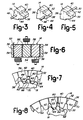
- a first pin 46 is shown which is adapted to contact first coil 28 for electromagnetic induction.
- Second pin 48 is shown in Figure 4, and is adapted to contact second coil 30.
- Third pin 50 is shown in Figure 5, and is adapted to contact third coil 32 for electromagnetic induction.
- an air gap 52 is provided between adjacent teeth 14.
- the air gap 52 between adjacent teeth 14 may be maintained by means of an insulative spacer 54 between the teeth.
- Spacer 54 is contacted on opposite sides by side wall 56 of one of the teeth 14 and side wall 58 of another of the teeth 14.
- Air gap 52 functions to minimize flux leakage between adjacent teeth 14.
- connections between first, second and third coils, 28, 30 and 32 and the first, second and third pins 46, 48 and 50 are shown in Figure 6 .
- Pinion gears 18 are of conventional design and include top lands 60, bottom lands 62 and first and second sides 66 and 64. As shown in Figure 7, pinion gear 18 is shown in a position of equilibrium wherein the first side 66 of pinion gear 18 engages first side 42 of one of the teeth 14, while second side 64 of the pinion gear 18 contacts a second side 44 of another of the teeth 14. As illustrated in Figures 6 and 7, the teeth are polarized, with a pattern of the first coil 28 being neutral, second coil 32 having a south polar charge, and third coil 30 having a north polar charge.
- the pinion gear 18 may be caused to shift a half-step to the position shown in Figure 8, wherein the first coil 28 has a north polar orientation, the second coil 32 has a north polar orientation and the third coil 30 has a south polar orientation.
- the pinion gear 18 will seek equilibrium wherein the pinion gear is centered over the tooth associated with the third coil having a south polar orientation.
- the pinion gear 18 assumes equilibrium over the tooth having a south polar orientation.
- the teeth and rotor are preferably formed of low reluctance, ferromagnetic, non-permanent magnetic material.
- low reluctance, ferromagnetic, non-permanent magnetic material For example, high nickel steel alloy or an amorphous silicone material may be used in the manufacture of the teeth of the stator or rotor. It is important to minimize the residual magnetism so that the stepper motor is quickly responsive. As stated above, one of the advantages of the invention is that there is no need for any permanent magnetic material or use of rare earth material in the stepper motor.
- a most preferred embodiment providing a carrier 20 with three pinion gears 18.
- three sets of teeth 14 would be provided by the ring gear 12, and in one example, 30 teeth may be provided in three sets of ten teeth.
- the pinion gears 18 will contact corresponding teeth of the same sets simultaneously.
- a stable moving mechanism is provided in the stepper motor.
- a linear actuator 74 is provided which is made up of a series of teeth 76.
- the teeth are divided into three sets of teeth, which are separately polarized to move a pinion gear 78.
- the linear actuator 74 operates in the same manner as the stepper motor 10 in other respects generally, but creates a linear output instead of a strictly rotational output.
- teeth 80 for use in the stepper motor 10 or linear actuator 74 is shown, wherein a separate coil 82 is provided for each of the teeth 80.
- a series of teeth 80 may be provided and connected to a source of electromagnetic force which would permit sets of coils 82 to be energized simultaneously.
- a gear stator having thirty teeth may have sixty step positions, incremented in six degree steps, by utilizing 12 properly sequenced states as shown in Figure 11.
- the first, second and third coils are in one of three conditions, north (denoted by "N"), south (denoted by "S") or neutral (denoted by a dash "-").
- N north
- S south
- neutral denoted by a dash "-"
- the rotor will assume a position centered over one of the teeth.
- two coils are excited, the rotor will assume a position with a tooth of the rotor lodged between a north and south pole. This provides an equilibrium one-half tooth pitch from the previous condition.
- the rotor is preferably a planetary gear set with ratios selected for desired output angle per step.
- a ring gear having thirty teeth would have a pitch diameter of 4.762 cms (1.875 inches).
- the rotor may be a pinion gear having twelve teeth with a pitch diameter of 0.19 cms. (0.075 inches). This would provide a pitch of sixteen.
- An output drive sun gear having twenty teeth can be provided in conjunction with a pinion gear having fourteen teeth or a pitch diameter of 0.4375. With a sun gear having twenty teeth, and a pitch diameter of 0.625, thirty-two pitch output may be provided.
- a stepper motor having a magnetic circuit in which air gaps are minimized is provided without requiring extreme manufacturing precision.
Landscapes
- Engineering & Computer Science (AREA)
- Power Engineering (AREA)
- Physics & Mathematics (AREA)
- Chemical & Material Sciences (AREA)
- Combustion & Propulsion (AREA)
- Electromagnetism (AREA)
- Linear Motors (AREA)
- Connection Of Motors, Electrical Generators, Mechanical Devices, And The Like (AREA)
Claims (8)
- Moteur pas-à-pas comprenant :un stator denté (12) comportant une pluralité de dents ferromagnétiques à faible réluctance, à magnétisme non permanent (14) formant des ensembles de pièces polaires disposés suivant une configuration alternée,un moyen (28, 30, 32) destiné à induire un flux magnétique indépendamment dans chacun desdits ensembles de pièces polaires,un moyen (52, 54) destiné à minimiser les fuites de flux entre les dents adjacentes,un rotor (16) comprenant au moins un pignon comportant des dents d'engrenage qui engrènent avec les dents du stator denté de telle façon qu'aucun entrefer n'est présent entre les pièces polaires dudit stator denté et les dents adjacentes dudit pignon de rotor en engrènement avec celles-ci, etun moyen destiné à commander les champs électromagnétiques opposés appliqués auxdits ensembles de pièces polaires formant les dents du stator denté, ledit moyen de commande faisant alterner en séquence le sens du champ électromagnétique appliqué auxdits ensembles de pièces polaires dans une direction désirée afin d'amener le rotor à se déplacer dans ladite direction, et maintenant le rotor en place en fixant la polarité de la charge électromagnétique appliquée auxdits ensembles de pièces polaires.
- Moteur pas-à-pas selon la revendication 1, dans lequel ledit stator denté (12) est une couronne dentée formée à partir d'une pluralité d'ensembles de dents d'engrenage (14) qui sont reliés les unes ou autres afin de former ledit stator denté (12), lesdits ensembles de dents d'engrenage (14) étant disposés suivant la configuration alternée.
- Moteur pas-à-pas selon la revendication 2, dans lequel ledit moyen destiné à induire un flux magnétique comprend trois enroulements toroïdaux (28, 30, 32) parmi lesquels chacun desdits enroulements est relié à l'un desdits ensembles de dents d'engrenage.
- Moteur pas-à-pas selon la revendication 2, dans lequel ledit moyen destiné à minimiser les fuites de flux entre les dents adjacentes comprend une pluralité d'entretoises isolantes (54) s'étendant radialement.
- Moteur pas-à-pas selon la revendication 1, dans lequel ledit stator denté est une crémaillère (76) et ledit rotor est un pignon (78).
- Moteur pas-à-pas selon la revendication 1, dans lequel ledit moyen destiné à induire un flux magnétique est une pluralité d'enroulements (28, 30, 32) reliés à l'une des dents du stator denté (12), lesdits enroulements étant reliés électriquement audit moyen destiné à commander les champs électromagnétiques opposés.
- Moteur pas-à-pas selon la revendication 1, dans lequel trois pignons (18) sont supportés par un porte-satellites (20), lesquels viennent en contact avec le stator (12) au niveau de trois points espacés, et engrènent simultanément avec des ensembles correspondants de pièces polaires.
- Moteur pas-à-pas selon la revendication 1, dans lequel ledit moyen destiné à commander les champs électromagnétiques opposés comprend un moyen destiné à appliquer séquentiellement des charges nord, sud et neutre aux ensembles de pièces polaires.
Applications Claiming Priority (2)
| Application Number | Priority Date | Filing Date | Title |
|---|---|---|---|
| US43048 | 1993-04-05 | ||
| US08/043,048 US5289065A (en) | 1993-04-05 | 1993-04-05 | Zero air gap orbiting gear stepper motor |
Publications (2)
| Publication Number | Publication Date |
|---|---|
| EP0619641A1 EP0619641A1 (fr) | 1994-10-12 |
| EP0619641B1 true EP0619641B1 (fr) | 1997-12-03 |
Family
ID=21925181
Family Applications (1)
| Application Number | Title | Priority Date | Filing Date |
|---|---|---|---|
| EP94302217A Expired - Lifetime EP0619641B1 (fr) | 1993-04-05 | 1994-03-28 | Moteur pas-à-pas |
Country Status (4)
| Country | Link |
|---|---|
| US (1) | US5289065A (fr) |
| EP (1) | EP0619641B1 (fr) |
| JP (1) | JPH06327192A (fr) |
| DE (1) | DE69407081T2 (fr) |
Families Citing this family (3)
| Publication number | Priority date | Publication date | Assignee | Title |
|---|---|---|---|---|
| DE19845914C2 (de) * | 1998-10-06 | 2000-08-24 | Bosch Gmbh Robert | Antriebsvorrichtung |
| CN109525094A (zh) * | 2018-12-24 | 2019-03-26 | 上海鑫国动力科技有限公司 | 一种步进式磁性齿轮 |
| EP4175603B1 (fr) * | 2020-07-06 | 2026-01-07 | Siemens Healthcare Diagnostics, Inc. | Ensemble destiné à être utilisé dans un dispositif de diagnostic médical et système d'analyse d'échantillons |
Family Cites Families (14)
| Publication number | Priority date | Publication date | Assignee | Title |
|---|---|---|---|---|
| US2703370A (en) * | 1952-07-02 | 1955-03-01 | Steensen Sverre Johan | Electric compressor or pump motor with rolling rotor |
| US2857536A (en) * | 1955-07-18 | 1958-10-21 | Edward C Light | Variable reluctance machine |
| US3147425A (en) * | 1961-10-30 | 1964-09-01 | Clary Corp | Pulse generator |
| DE1930389A1 (de) * | 1969-03-03 | 1970-09-10 | Erich Diessner Kg Ing | Zaehlvorrichtung zum elektromechanischen Vor- und Rueckwaertszaehlen von elektrischen Impulsen mit Sicherheitsaussage |
| US3561006A (en) * | 1969-05-22 | 1971-02-02 | Usm Corp | Electromagnetic actuators with deflectible rotor |
| DE2206660A1 (de) * | 1971-02-11 | 1972-08-31 | Pratt Precision Hydraulics Ltd | Elektrischer Schrittschaltmotor |
| USRE27446E (en) * | 1971-06-07 | 1972-08-01 | Welch motor with gyrating rotor | |
| SU809450A1 (ru) * | 1978-12-25 | 1981-02-28 | Belesin Valentin | Электрический двигатель |
| US4358694A (en) * | 1979-08-15 | 1982-11-09 | Nathan Grundland | Selectably positionable rotary transducers |
| GB8405253D0 (en) * | 1984-02-29 | 1984-04-04 | Peritronic Medical Ind Plc | Controlling stepping motor |
| JPS62254655A (ja) * | 1986-04-25 | 1987-11-06 | Yamatake Honeywell Co Ltd | 回転機 |
| US4780636A (en) * | 1987-02-27 | 1988-10-25 | General Electric Company | Lip structure for a stator in a dynamo-electric machine |
| JPH02114853A (ja) * | 1988-10-21 | 1990-04-26 | Bitsugu:Kk | 動力発生装置 |
| DE4018421A1 (de) * | 1990-06-06 | 1994-11-17 | Mannesmann Ag | Steuerung für einen Schrittmotor |
-
1993
- 1993-04-05 US US08/043,048 patent/US5289065A/en not_active Expired - Lifetime
-
1994
- 1994-03-28 EP EP94302217A patent/EP0619641B1/fr not_active Expired - Lifetime
- 1994-03-28 DE DE69407081T patent/DE69407081T2/de not_active Expired - Fee Related
- 1994-04-04 JP JP6066262A patent/JPH06327192A/ja active Pending
Also Published As
| Publication number | Publication date |
|---|---|
| US5289065A (en) | 1994-02-22 |
| EP0619641A1 (fr) | 1994-10-12 |
| JPH06327192A (ja) | 1994-11-25 |
| DE69407081T2 (de) | 1998-03-26 |
| DE69407081D1 (de) | 1998-01-15 |
Similar Documents
| Publication | Publication Date | Title |
|---|---|---|
| US4127802A (en) | High torque stepping motor | |
| EP0581612B1 (fr) | Moteur hybride pas-à-pas multiphases | |
| US4330727A (en) | Electric step motor | |
| JP2008161053A (ja) | 二相電動機 | |
| US3790834A (en) | Low speed synchronous motor | |
| USRE29411E (en) | Harmonic drive for digital step motor | |
| JP2738199B2 (ja) | 回転又は移動検出方法及びその装置 | |
| US3579276A (en) | Harmonic drive for digital step motor | |
| KR100363909B1 (ko) | 두개의 회전자를 가진 다극 모터 | |
| US4714854A (en) | Electric motor with a multipolar permanent magnet rotor | |
| KR910008675B1 (ko) | 스테핑 모터를 구비한 전기기계식 시계장치 | |
| US4792709A (en) | Winding for operation of a three-phase stepping motor from a two-phase drive | |
| EP0619641B1 (fr) | Moteur pas-à-pas | |
| US5321330A (en) | Electromagnetic transducer with a multipolar permanent magnet | |
| JPH10191606A (ja) | 2個の同軸ロータを有する電磁モータ | |
| JP2008029194A (ja) | ステッピングモータ | |
| US3644764A (en) | Harmonic drive for digital step motor | |
| EP0319632B1 (fr) | Moteur électrique à rotor multipôlaire à aimants permanents | |
| JP2669683B2 (ja) | 波動歯車の波動発生器 | |
| EP0696836B1 (fr) | Moteur électromagnétique pas à pas à deux sens de rotation | |
| EP1067657B1 (fr) | Actionneur à angle de rotation limité | |
| GB2282009A (en) | Using magnetic drive permanent magnets | |
| JPS59172949A (ja) | 複合ブラシレスサ−ボモ−タ | |
| JPS6355301B2 (fr) | ||
| JP2002136095A (ja) | ステッピングモータ |
Legal Events
| Date | Code | Title | Description |
|---|---|---|---|
| PUAI | Public reference made under article 153(3) epc to a published international application that has entered the european phase |
Free format text: ORIGINAL CODE: 0009012 |
|
| AK | Designated contracting states |
Kind code of ref document: A1 Designated state(s): DE FR GB |
|
| 17P | Request for examination filed |
Effective date: 19950302 |
|
| 17Q | First examination report despatched |
Effective date: 19960826 |
|
| GRAG | Despatch of communication of intention to grant |
Free format text: ORIGINAL CODE: EPIDOS AGRA |
|
| GRAG | Despatch of communication of intention to grant |
Free format text: ORIGINAL CODE: EPIDOS AGRA |
|
| GRAH | Despatch of communication of intention to grant a patent |
Free format text: ORIGINAL CODE: EPIDOS IGRA |
|
| GRAH | Despatch of communication of intention to grant a patent |
Free format text: ORIGINAL CODE: EPIDOS IGRA |
|
| GRAA | (expected) grant |
Free format text: ORIGINAL CODE: 0009210 |
|
| AK | Designated contracting states |
Kind code of ref document: B1 Designated state(s): DE FR GB |
|
| REF | Corresponds to: |
Ref document number: 69407081 Country of ref document: DE Date of ref document: 19980115 |
|
| ET | Fr: translation filed | ||
| PLBE | No opposition filed within time limit |
Free format text: ORIGINAL CODE: 0009261 |
|
| STAA | Information on the status of an ep patent application or granted ep patent |
Free format text: STATUS: NO OPPOSITION FILED WITHIN TIME LIMIT |
|
| 26N | No opposition filed | ||
| PGFP | Annual fee paid to national office [announced via postgrant information from national office to epo] |
Ref country code: FR Payment date: 20010316 Year of fee payment: 8 |
|
| REG | Reference to a national code |
Ref country code: GB Ref legal event code: IF02 |
|
| PG25 | Lapsed in a contracting state [announced via postgrant information from national office to epo] |
Ref country code: FR Free format text: LAPSE BECAUSE OF NON-PAYMENT OF DUE FEES Effective date: 20021129 |
|
| REG | Reference to a national code |
Ref country code: FR Ref legal event code: ST |
|
| PGFP | Annual fee paid to national office [announced via postgrant information from national office to epo] |
Ref country code: GB Payment date: 20040316 Year of fee payment: 11 Ref country code: DE Payment date: 20040316 Year of fee payment: 11 |
|
| PG25 | Lapsed in a contracting state [announced via postgrant information from national office to epo] |
Ref country code: GB Free format text: LAPSE BECAUSE OF NON-PAYMENT OF DUE FEES Effective date: 20050328 |
|
| PG25 | Lapsed in a contracting state [announced via postgrant information from national office to epo] |
Ref country code: DE Free format text: LAPSE BECAUSE OF NON-PAYMENT OF DUE FEES Effective date: 20051001 |
|
| GBPC | Gb: european patent ceased through non-payment of renewal fee |
Effective date: 20050328 |