EP0620160A2 - Système de fermeture encliquetable et méthode - Google Patents
Système de fermeture encliquetable et méthode Download PDFInfo
- Publication number
- EP0620160A2 EP0620160A2 EP94302361A EP94302361A EP0620160A2 EP 0620160 A2 EP0620160 A2 EP 0620160A2 EP 94302361 A EP94302361 A EP 94302361A EP 94302361 A EP94302361 A EP 94302361A EP 0620160 A2 EP0620160 A2 EP 0620160A2
- Authority
- EP
- European Patent Office
- Prior art keywords
- interlocking
- spout
- container neck
- cap
- sealing ring
- Prior art date
- Legal status (The legal status is an assumption and is not a legal conclusion. Google has not performed a legal analysis and makes no representation as to the accuracy of the status listed.)
- Withdrawn
Links
- 238000000034 method Methods 0.000 title claims description 5
- 238000007789 sealing Methods 0.000 claims abstract description 173
- 230000000452 restraining effect Effects 0.000 claims description 23
- 210000005069 ears Anatomy 0.000 claims description 13
- 230000002093 peripheral effect Effects 0.000 claims description 4
- 238000005096 rolling process Methods 0.000 claims description 3
- 239000004033 plastic Substances 0.000 description 9
- 238000002788 crimping Methods 0.000 description 6
- 230000006870 function Effects 0.000 description 3
- 238000004519 manufacturing process Methods 0.000 description 3
- 238000011109 contamination Methods 0.000 description 2
- 238000009434 installation Methods 0.000 description 2
- 239000002184 metal Substances 0.000 description 2
- 230000004048 modification Effects 0.000 description 2
- 238000012986 modification Methods 0.000 description 2
- 238000004064 recycling Methods 0.000 description 2
- 239000012815 thermoplastic material Substances 0.000 description 2
- 230000009471 action Effects 0.000 description 1
- 230000004075 alteration Effects 0.000 description 1
- 230000007812 deficiency Effects 0.000 description 1
- 230000007246 mechanism Effects 0.000 description 1
- 238000000465 moulding Methods 0.000 description 1
- 230000001737 promoting effect Effects 0.000 description 1
- 238000000926 separation method Methods 0.000 description 1
Images


Classifications
-
- B—PERFORMING OPERATIONS; TRANSPORTING
- B65—CONVEYING; PACKING; STORING; HANDLING THIN OR FILAMENTARY MATERIAL
- B65D—CONTAINERS FOR STORAGE OR TRANSPORT OF ARTICLES OR MATERIALS, e.g. BAGS, BARRELS, BOTTLES, BOXES, CANS, CARTONS, CRATES, DRUMS, JARS, TANKS, HOPPERS, FORWARDING CONTAINERS; ACCESSORIES, CLOSURES, OR FITTINGS THEREFOR; PACKAGING ELEMENTS; PACKAGES
- B65D47/00—Closures with filling and discharging, or with discharging, devices
- B65D47/04—Closures with discharging devices other than pumps
- B65D47/06—Closures with discharging devices other than pumps with pouring spouts or tubes; with discharge nozzles or passages
- B65D47/061—Closures with discharging devices other than pumps with pouring spouts or tubes; with discharge nozzles or passages with telescopic, retractable or reversible spouts, tubes or nozzles
- B65D47/063—Closures with discharging devices other than pumps with pouring spouts or tubes; with discharge nozzles or passages with telescopic, retractable or reversible spouts, tubes or nozzles with flexible parts
Definitions
- This invention relates generally to a closure system for a container that includes a snap-on cap and spout assembly for receipt onto a container neck and, more specifically, to a cap and spout assembly and method for assembling the cap and spout assembly onto a container wherein the cap and spout assembly includes a snap-on tamper evident cap and a snap-on pouring spout.
- closures for sealing onto a container neck include a spout received onto the neck of a container and a cap for closure of the spout.
- the cap is threaded onto the spout, and the spout and/or cap is either threaded with the container neck or clamped onto the container neck via a separate crimping ring.
- U.S. Patent Nos. 4,236,629 to Dwinell, 4,632,282 to Nagashima and 4,568,006 to Mueller, et al. disclose various crimping ring arrangements for clamping the spout onto the container neck, wherein the crimping ring is constructed of a malleable metal.
- U.S. Patent No. 5,004,126 to Klesius discloses a plastic closure for a plastic container that includes a frame cap adapted to be screwed onto an externally threaded container neck over a flexible pouring spout.
- the frame cap is frangibly attached to and integral with a screw-on ring adapted to be threaded onto the externally threaded container neck.
- One disadvantage of this type of closure is the possibility of breaking the frame cap from the screw-on ring during threading of the ring onto the container neck.
- closures that seal onto a container neck include a snap-on spout received onto the container neck and a cap threaded onto the container neck over the snap-on spout.
- U.S. Patent No. 4,917,270 to Simon discloses a closure device that includes a spout received into a groove provided on the container neck, wherein the spout resiliently deforms over the container neck during installation to seat in the groove.
- U.S. Patent Nos. 5,108,009 to Davidson et al. and 4,706,829 to Li disclose other similar interlocking spout and container neck configurations. Still, there is always a need for an improved snap-on closure for universal use with a variety of spouts.
- both the Li and Davidson closures include a stiff spout constructed of a relatively hard plastic that is molded to a fixed configuration.
- the spout alone provides the necessary resilient interlocking force required to seal onto the container neck, so that the cap is not required to enhance the spout/container neck seal and can therefore be entirely removed from the coiitainer neck.
- Other more flexible spouts present additional sealing problems beyond those addressed by the Simon, Davidson, et al. and Li closures.
- Such a closure should provide improved sealing characteristics for high internal container pressures, such as that resulting from impact or dropping of the container, while still being easily assembled together onto the container neck.
- the closure should be constructed entirely of plastic and easily molded to facilitate manufacturing.
- the closure should be tamper evident and also easily installed onto a container neck without risk of damage to the tamper evident means.
- a closure system for a container includes a container neck extending axially from a container, a spout including means for sealing onto the container neck, first means for axially interlocking the spout with the container neck, the first means being resiliently flexible to snap onto the container neck, a cap including means for closing of the spout, and second means for axially interlocking the cap with the container neck, the second means being resiliently flexible to snap onto the container neck, the first means interlocking the spout with the container neck and the second means interlocking the cap with the container neck over the spout wherein the first means and the second means maintain the spout in sealing contact against the container neck.
- a snap-on tamper evident closure assembly is also disclosed according to one embodiment of the present invention that includes a snap-on spout having a resiliently flexible sealing ring adapted for sealing receipt onto the container neck, the sealing ring including a first interlocking lip adapted for interlocking with a corresponding first interlocking lip of the container neck, the sealing ring being resiliently flexible to snap onto the container neck, a snap-on cap including a closure member for closure of the spout and an interlocking ring adapted for interlocking receipt onto the container neck over the sealing ring, the closure member being frangibly attached to the interlocking ring, the interlocking ring including a second interlocking lip adapted for interlocking with a corresponding second interlocking lip of the container neck, the interlocking ring being resiliently flexible to snap onto t.he container neck, wherein the second interlocking lip of the interlocking ring extends below the first interlocking lip of the sealing ring when the spout and the cap are received
- a closure assembly is further disclosed according to one embodiment of the present invention that includes a container neck extending axially from a container, the container neck including an inner sealing surface and an outer sealing surface, a spout including a sealing ring for sealing receipt onto the container neck, the sealing ring including an inner sealing ring portion for sealing against the inner sealing surface of the container neck, an outer sealing ring portion for sealing against the outer sealing surface of the container neck, and a transverse sealing ring portion attached between the inner sealing ring portion and the outer sealing ring portion and bridging the container neck, and means for axially restraining the sealing ring against the container neck, wherein the means for axially restraining defines a pivot for the sealing ring to roll thereagainst when the inner sealing ring portion is forced out of sealing contact against the inner surface of the container neck, the sealing ring rolling about the means for axially restraining to increase the sealing contact of the outer sealing ring portion against the outer sealing surface of the container neck.
- a method for assembling a closure onto a container neck includes the steps of obtaining a spout including means for sealing onto a container neck and first means for axially interlocking the spout with the container neck, the first means being resiliently flexible to snap onto the container neck, obtaining a cap including means for closing of the spout and second means for axially interlocking the cap with the container neck, the second means being resiliently flexible to snap onto the container neck, assembling the cap onto the spout to form a cap and spout assembly, and axially assembling the cap and spout assembly onto the container neck, the first means and the second means resiliently flexing to snap onto the container neck.
- One object of the present invention is to provide an improved closure system for a container that assembles onto the container in a single step.
- Another object of the present invention is to provide a closure having improved sealing characteristics.
- Yet another object of the present invention is to provide a closure constructed entirely of plastic to facilitate manufacturing and recycling of the package system.
- Still another object of the present invention is to provide a closure that is tolerant of variances in the container opening.
- Still yet another object of the present invention is to provide a tamper evident threaded closure that is easily installed onto a container neck.
- Another object of the present invention is to provide a tamper evident closure employing frangible means and which is resistant to breakage of the frangible means during installation onto the container neck.
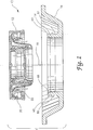
- FIG. 1 is an exploded view of a closure system according to the present invention that includes a cap and spout assembly received onto a container neck.
- FIG. 2 is an exploded view of the cap and spout assembly of FIG. 1.
- FIG. 3 is a top plan view of the cap of FIG. 2.
- FIG. 4 is a top plan view of the spout of FIG. 2.
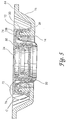
- FIG. 5 is a side elevational, cross-sectional view of the closure system of FIG. 1 as assembled, wherein the views of the cap and spout are taken in the direction of the arrows indicated in FIGS. 3 and 4, respectively.
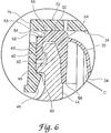
- FIG. 6 is a partial enlarged view of the FIG. 5 assembly depicting in detail its various sealing interfaces.
- a closure system 10 including a cap and spout assembly 12 adapted for snap-on receipt onto a container neck 14 of a container lid 16.
- cap and spout assembly 12 assembles onto container neck 14 generally axially along central axis 18 by snapping onto container neck 14.
- the various components of closure system 10 are flexible to facilitate the snap-on action of cap and spout assembly 12 onto container neck 14.
- the components of closure system 10 are constructed of plastic and are easily molded to facilitate manufacturing. Also, by constructing the components of closure system 10 entirely from plastic, closure system 10 is easily recycled without disasseinbly or separation of its various components.
- Cap and spout assembly 12 includes a cap 20 flexibly received over a spout 22. Unlike prior art closures which sequentially assemble onto a container neck, cap and spout assembly 12 assembles onto container neck 14 in a single step. As such, cap and spout assembly 12 does away with interim assembly steps which may leave the contents of the container susceptible to tampering or contamination. Further, by snapping onto the container neck as an assembly rather than as individual components, cap and spout assembly does away with separate assembly tooling specifically adapted to the spout.
- Cap 20 includes generally a closure member 24 frangibly attached to an interlocking outer ring member 26 via bail handles 72 and 74 and frangible tabs 28.
- Interlocking member 26 is constructed of a thermoplastic material and is resiliently flexible to interlock with container neck 14 and restrain spout 22 in sealing contact against container neck 14.
- Cap 20 is a tamper evident cap, wherein tamper evident means is provided by the axially interlocking relationship between interlocking member 26 and container neck 14 and the frangible attachment of interlocking member 26 to closure member 24 via frangible tabs 28.
- Spout 22 is a flexible spout to aid in pouring.
- Spout 22 includes a pouring neck 30 disposed within a sealing ring 32 and a flexible web 34 sealingly attached between pouring neck 30 and sealing ring 32.
- Pouring neck 30 is positionable between a nested position within sealing ring 32 and an extended position (not shown) upstanding from sealing ring 32.
- spout 22 is a flexible spout, it is constructed from a flexible thermoplastic material similar to that of cap 20.
- spout 22 is not so resilient to detract from it flexing between nested and extended positions and being able to sealingly conform to dimensional variations of the container neck upon being clamped thereagainst by interlocking ring member 26.
- Cap 20 assembles with spout 22 to form cap and spout assembly 12 by closure member 24 threading onto pouring neck 30.
- closure member 24 includes two threads 36 and 38 having thread start or engagement positions spaced opposite from one another within closure member 24 to facilitate threaded engagement of the cap with the spout every half turn.
- pouring neck 30 includes two threads 40 and 42 to provide corresponding multiple thread engagement positions.
- closure member 24 further includes a circular sealing ridge 44 which defines a circular groove 46 for receiving the upper edge of pouring neck 30 in sealing contact therein.
- Interlocking ring member 26 includes an interlocking lip 48 extending radially inward thereof and below sealing ring 32 when assembled over spout 22, wherein interlocking lip 48 interlocks with a corresponding interlocking lip 50 of container neck 14 (FIG. 1).
- interlocking lip 48 resiliently flexes radially outward to snap over sealing ring 32.
- closure member 24 is further tightened onto pouring neck 30, sealing ring 32 is drawn up to seat against interlocking ring member 26.
- interlocking ring member 26 includes a restraining lip 52 which seats against a corresponding groove 54 of sealing ring 32. Interlocking ring member 26 and restraining lip 52 cooperate to improve the sealing characteristics of sealing ring 32 at high internal container pressures as discussed further below, in particular in connection with FIG. 6.
- cap and spout assembly 12 is snapped onto container neck 14.
- an axially tight fit results between the cap, spout and container neck so that there is little to no axially play between the various components.
- any threading of closure member 24 off of spout 22 retracts closure member 24 axially outward away from container neck 14.
- interlocking ring member 26 is axially restrained in place onto container neck 14, the differential axial movement between the closure member and the interlocking ring causes frangible tabs 28 to break, thereby evidencing access to the contents of the container.
- interlocking ring member 26 functions independently of closure member 24 to still maintain positive sealing across the sealing ring to container neck interface at high internal pressures within the container.
- Interlocking ring member 26 similarly serves to restrain sealing ring 32 snapped onto container neck 14 when force is exerted to extend spout 22.
- container neck 14 extends axially upward from a recessed configuration in which cap and spout assembly 12 is received onto container neck 14 substantially flush with surface 84 of container lid 16.
- cap and spout assembly 12 is received onto container neck 14 substantially flush with surface 84 of container lid 16.
- sealing ring 32 is generally U-shaped in cross-section and includes a transverse sealing ring portion 56 generally forming the bottom of the "U” and an inner sealing ring portion 58 and an outer sealing ring portion 60 generally forming the sides of the "U".
- An interlocking lip 62 extends radially inward of outer sealing ring portion 60 to interlock with a corresponding interlocking lip 63 of container neck 14 (FIG. 1).
- sealing ring 32 and interlocking ring member 26 interlock with container neck 14 independent of one another. As a result, interlocking ring member 26 maintains sealing ring 32 clamped against container neck 14 at high internal pressures within the container.
- interlocking ring member 26 prevents lip 62 of sealing ring 32 from "popping" off of lip 63 of container neck 14 when the container is pressurized. Further, by initially interlocking cap 20 with container neck 14, cap 20 also prevents pouring neck 30 from extending when the container is pressurized. As such, an improved sealing system results that protects against leakage upon pressurization of the container.
- inner sealing ring portion 58 also includes a tapered sealing surface 64 corresponding to a tapered inner sealing ring surface 65 of container neck 14 (FIG. 1).
- interlocking ring member 26 cooperates with sealing ring 32 to actively counter the unseating of inner sealing ring portion 58 by improving the sealing of outer sealing ring portion 60.
- FIG. 6 the cooperation of interlocking ring member 26 with sealing ring 32 is shown in greater detail.
- Restraining lip 52 is molded within interlocking ling member 26 spaced approximately the same axial distance from interlocking lip 48 as the assembled axial distance between groove 54 of sealing ring 32 and interlocking lip 50 of container neck 14.
- Sealing ring 32 seals against container neck 14 both internally via inner sealing ring portion 58 and externally via outer sealing ring portion 60. Nevertheless, at high internal container pressures such as that resulting from impact or dropping of the container, inner sealing ring portion 58 is prone to lifting off of and radially inward away from container neck 14.
- sealing ring 32 is prevented from lifting off of container neck 14. Instead, as inner sealing ring portion 58 rotates to lift off of container neck 14, sealing ring 32 rolls or pivots against restraining lip 52 to drive outer sealing ring portion 60 and lip 62 in greater sealing contact against interlocking lip 63 of container neck 14.
- Lip 55 is provided at least in part for molding requirements and convenience. Lip 55 may also react against surface 53 of restraining lip 52 as part of or due to any rolling or pivoting motion of sealing ring 32. Lip 55 could also provide a third annular sealing interface against surface 53 if the ring member 26 is continuous and does not include recesses 80 and 82.
- spout 22 also includes a frangible sealing diaphragm 68 sealingly attached across pouring neck 30 and a pull ring 70 attached to sealing diaphragm 68.
- closure means are provided for spout 22 whereby pouring neck 30 is sealed until pull ring 70 is engaged to break frangible sealing diaphragm 68 free of pouring neck 30.
- spout 22 further includes a plurality of vent ears 66 attached to flexible web 34. Ears 66 extend downwardly from flexible web 34 when spout 22 is in its stored position nested within sealing ring 32. When spout 22 is in its extended position with pouring neck 30 upstanding from sealing ring 32, ears 66 extend radially inward within the spout and cooperate to define a central flow aperture and a plurality of peripheral vent openings. Vent ears 66 function similar to those disclosed in U.S. Patent No. 4,555,048 to Hamman et al. issued November 26, 1985, the disclosure of which is hereby incorporated by reference, and U.S. Patent No. 4,618,078 to Hamman et al. issued October 21, 1986, the disclosure of which is also hereby incorporated by reference.
- flexible bail handles 72 and 74 are flexible between a stored position flush with closure member 24 and a usable position upstanding from closure member 24.
- tabs 76 and 78 are provided which extend radially outward of bail handles 72 and 74, respectively.
- Interlocking ring member 26 similarly includes a corresponding pair of oppositely spaced recesses 80 and 82 for receiving tabs 76 and 78. As such, tabs 76 and 78 are easily accessible when pull rings 72 and 74 are in their initial stored position and frangibly attached to interlocking ring member 26. Such a configuration is particularly well suited for a recessed container neck such as that shown in FIG. 5.
Landscapes
- Engineering & Computer Science (AREA)
- Mechanical Engineering (AREA)
- Closures For Containers (AREA)
Applications Claiming Priority (2)
| Application Number | Priority Date | Filing Date | Title |
|---|---|---|---|
| US4677893A | 1993-04-13 | 1993-04-13 | |
| US46778 | 1993-04-13 |
Publications (2)
| Publication Number | Publication Date |
|---|---|
| EP0620160A2 true EP0620160A2 (fr) | 1994-10-19 |
| EP0620160A3 EP0620160A3 (fr) | 1994-12-21 |
Family
ID=21945347
Family Applications (1)
| Application Number | Title | Priority Date | Filing Date |
|---|---|---|---|
| EP94302361A Withdrawn EP0620160A3 (fr) | 1993-04-13 | 1994-03-31 | Système de fermeture encliquetable et méthode. |
Country Status (5)
| Country | Link |
|---|---|
| EP (1) | EP0620160A3 (fr) |
| JP (1) | JPH06345111A (fr) |
| AU (1) | AU5902694A (fr) |
| BR (1) | BR9401463A (fr) |
| CA (1) | CA2119695A1 (fr) |
Cited By (8)
| Publication number | Priority date | Publication date | Assignee | Title |
|---|---|---|---|---|
| EP0779227A1 (fr) * | 1995-12-08 | 1997-06-18 | Rieke Corporation | Ensemble de fermeture avec goulotte de décharge escamotable |
| EP0922646A1 (fr) * | 1997-12-12 | 1999-06-16 | Invat S.R.L. | Bec extensible muni d' un capuchon à vis et anneau d' inviolabilité |
| DE19807768A1 (de) * | 1998-02-24 | 1999-08-26 | Bericap Gmbh & Co | Kunststoffdeckel mit Kunststoffverschluß |
| SG138553A1 (en) * | 2006-06-12 | 2008-01-28 | Rieke Corp | Container closure assembly with extendable spout and tamper-evident portion |
| EP2418157A1 (fr) | 2010-08-13 | 2012-02-15 | Ball Packaging Europe GmbH | Accrochage de fixation d'un couvercle de canette métallique et procédé pour la fixation du couvercle sur la canette métallique |
| ITFI20130151A1 (it) * | 2013-06-27 | 2014-12-28 | Ta Plast S R L Fa | Un perfezionamento di un tappo versatore per bottiglie alimentari per il contenimento di olio |
| EP2257475A4 (fr) * | 2008-02-27 | 2015-04-29 | Apc Products Ltd | Fermetures pour récipients en plastique conçues pour moulage d insert automatisé |
| US12551738B2 (en) | 2022-05-04 | 2026-02-17 | Rieke Llc | Retractable spout closure system with flame mitigation |
Families Citing this family (1)
| Publication number | Priority date | Publication date | Assignee | Title |
|---|---|---|---|---|
| GB201704181D0 (en) * | 2014-09-16 | 2017-05-03 | Rieke Corp | Closure for a container lid |
Family Cites Families (7)
| Publication number | Priority date | Publication date | Assignee | Title |
|---|---|---|---|---|
| JPS5930070A (ja) * | 1982-08-13 | 1984-02-17 | Kokusai Denshin Denwa Co Ltd <Kdd> | 大規模メモリ装置の検査方法 |
| US4632282A (en) * | 1984-03-02 | 1986-12-30 | Hirohisa Nagashima | Spout assembly |
| US4555048A (en) * | 1984-05-16 | 1985-11-26 | Rieke Corporation | Vented nestable pouring spout |
| FR2609968B2 (fr) * | 1986-11-12 | 1989-06-02 | Remy Ets Pierre | Dispositif a bec verseur escamotable et extensible |
| NL8800929A (nl) * | 1988-04-11 | 1989-11-01 | Leer Koninklijke Emballage | Houder of vat. |
| EP0417453A1 (fr) * | 1989-09-11 | 1991-03-20 | Invat S.R.L. | Capuchon extensible pour bouteille ou bidon avec système anti-vol |
| DE4104613A1 (de) * | 1991-02-15 | 1992-08-20 | Berg Jacob Gmbh Co Kg | Verschlusskappe fuer kunststoffverschluss |
-
1994
- 1994-03-23 CA CA 2119695 patent/CA2119695A1/fr not_active Abandoned
- 1994-03-23 AU AU59026/94A patent/AU5902694A/en not_active Abandoned
- 1994-03-31 EP EP94302361A patent/EP0620160A3/fr not_active Withdrawn
- 1994-04-11 BR BR9401463A patent/BR9401463A/pt active Search and Examination
- 1994-04-13 JP JP6074805A patent/JPH06345111A/ja active Pending
Cited By (13)
| Publication number | Priority date | Publication date | Assignee | Title |
|---|---|---|---|---|
| EP0779227A1 (fr) * | 1995-12-08 | 1997-06-18 | Rieke Corporation | Ensemble de fermeture avec goulotte de décharge escamotable |
| US5797525A (en) * | 1995-12-08 | 1998-08-25 | Rieke Corporation | Nestable pouring spout assembly |
| EP0922646A1 (fr) * | 1997-12-12 | 1999-06-16 | Invat S.R.L. | Bec extensible muni d' un capuchon à vis et anneau d' inviolabilité |
| CN1103723C (zh) * | 1998-02-24 | 2003-03-26 | 伯里凯普有限两合公司 | 带有塑料锁闭件的塑料盖 |
| WO1999043567A1 (fr) * | 1998-02-24 | 1999-09-02 | Bericap Gmbh & Co. Kg | Couvercle plastique a obturateur plastique |
| AU748929B2 (en) * | 1998-02-24 | 2002-06-13 | Bericap Gmbh & Co. Kg | Plastic lid with plastic seal |
| DE19807768A1 (de) * | 1998-02-24 | 1999-08-26 | Bericap Gmbh & Co | Kunststoffdeckel mit Kunststoffverschluß |
| SG138553A1 (en) * | 2006-06-12 | 2008-01-28 | Rieke Corp | Container closure assembly with extendable spout and tamper-evident portion |
| EP2257475A4 (fr) * | 2008-02-27 | 2015-04-29 | Apc Products Ltd | Fermetures pour récipients en plastique conçues pour moulage d insert automatisé |
| EP2418157A1 (fr) | 2010-08-13 | 2012-02-15 | Ball Packaging Europe GmbH | Accrochage de fixation d'un couvercle de canette métallique et procédé pour la fixation du couvercle sur la canette métallique |
| WO2012028443A1 (fr) | 2010-08-13 | 2012-03-08 | Ball Packaging Europe Gmbh | Fixation de couvercle pour boîte métallique et procédé de fixation d'un couvercle sur une boîte métallique |
| ITFI20130151A1 (it) * | 2013-06-27 | 2014-12-28 | Ta Plast S R L Fa | Un perfezionamento di un tappo versatore per bottiglie alimentari per il contenimento di olio |
| US12551738B2 (en) | 2022-05-04 | 2026-02-17 | Rieke Llc | Retractable spout closure system with flame mitigation |
Also Published As
| Publication number | Publication date |
|---|---|
| AU5902694A (en) | 1994-10-20 |
| EP0620160A3 (fr) | 1994-12-21 |
| CA2119695A1 (fr) | 1994-10-14 |
| JPH06345111A (ja) | 1994-12-20 |
| BR9401463A (pt) | 1994-10-18 |
Similar Documents
| Publication | Publication Date | Title |
|---|---|---|
| US5641099A (en) | Nestable pouring spout assembly | |
| US4487326A (en) | Carbonated beverage package | |
| US4709823A (en) | Tamper evident bottle or package closure | |
| US4387817A (en) | Child resistant container cover | |
| CA1123384A (fr) | Contenant verseur refermable a bague de separation sur fermeture | |
| US4305517A (en) | Tamperproof closure | |
| EP0770560B1 (fr) | Fermeture inviolable à l'épreuve des enfants | |
| US5456374A (en) | Tamper evident container closure | |
| US5680965A (en) | Tamper evident container closure | |
| US5450973A (en) | Tamper-evident closure apparatus | |
| US4180178A (en) | Container and closure | |
| US3572413A (en) | Container and snap-on cover | |
| EP2018328B1 (fr) | Fermeture | |
| US5129531A (en) | Closure assembly with breakaway tamper evident membrane | |
| US6299005B1 (en) | Closure | |
| US20030015490A1 (en) | Container closure | |
| US5271512A (en) | Tamper-evident closure with reinforced band | |
| US4485934A (en) | Tamperproof closure | |
| EP0440480B1 (fr) | Emballage résistant aux enfants | |
| GB2190903A (en) | Tamper indicating package | |
| US6260722B1 (en) | Cap and container assembly | |
| CA1285525C (fr) | Fermeture et emballage de surete | |
| US5950851A (en) | Safety closure and container having biasing means | |
| US5622273A (en) | Resealable snap-fit plastic closure | |
| US4141475A (en) | Locking device for a self-closing closure |
Legal Events
| Date | Code | Title | Description |
|---|---|---|---|
| PUAI | Public reference made under article 153(3) epc to a published international application that has entered the european phase |
Free format text: ORIGINAL CODE: 0009012 |
|
| AK | Designated contracting states |
Kind code of ref document: A2 Designated state(s): AT BE CH DE DK ES FR GB GR IE IT LI LU MC NL PT SE |
|
| PUAL | Search report despatched |
Free format text: ORIGINAL CODE: 0009013 |
|
| AK | Designated contracting states |
Kind code of ref document: A3 Designated state(s): AT BE CH DE DK ES FR GB GR IE IT LI LU MC NL PT SE |
|
| 17P | Request for examination filed |
Effective date: 19950213 |
|
| 17Q | First examination report despatched |
Effective date: 19951201 |
|
| STAA | Information on the status of an ep patent application or granted ep patent |
Free format text: STATUS: THE APPLICATION IS DEEMED TO BE WITHDRAWN |
|
| 18D | Application deemed to be withdrawn |
Effective date: 19960312 |