EP0620355A1 - Jalousie horizontale variable - Google Patents
Jalousie horizontale variable Download PDFInfo
- Publication number
- EP0620355A1 EP0620355A1 EP94301855A EP94301855A EP0620355A1 EP 0620355 A1 EP0620355 A1 EP 0620355A1 EP 94301855 A EP94301855 A EP 94301855A EP 94301855 A EP94301855 A EP 94301855A EP 0620355 A1 EP0620355 A1 EP 0620355A1
- Authority
- EP
- European Patent Office
- Prior art keywords
- cord
- slats
- support
- cords
- lifting
- Prior art date
- Legal status (The legal status is an assumption and is not a legal conclusion. Google has not performed a legal analysis and makes no representation as to the accuracy of the status listed.)
- Withdrawn
Links
- 238000003780 insertion Methods 0.000 claims description 6
- 230000037431 insertion Effects 0.000 claims description 6
- 238000010586 diagram Methods 0.000 description 5
- 238000000034 method Methods 0.000 description 2
- 238000012986 modification Methods 0.000 description 2
- 230000004048 modification Effects 0.000 description 2
- 238000004804 winding Methods 0.000 description 2
- 238000004519 manufacturing process Methods 0.000 description 1
- 230000000414 obstructive effect Effects 0.000 description 1
- 230000000630 rising effect Effects 0.000 description 1
Images



Classifications
-
- E—FIXED CONSTRUCTIONS
- E06—DOORS, WINDOWS, SHUTTERS, OR ROLLER BLINDS IN GENERAL; LADDERS
- E06B—FIXED OR MOVABLE CLOSURES FOR OPENINGS IN BUILDINGS, VEHICLES, FENCES OR LIKE ENCLOSURES IN GENERAL, e.g. DOORS, WINDOWS, BLINDS, GATES
- E06B9/00—Screening or protective devices for wall or similar openings, with or without operating or securing mechanisms; Closures of similar construction
- E06B9/24—Screens or other constructions affording protection against light, especially against sunshine; Similar screens for privacy or appearance; Slat blinds
- E06B9/26—Lamellar or like blinds, e.g. venetian blinds
- E06B9/28—Lamellar or like blinds, e.g. venetian blinds with horizontal lamellae, e.g. non-liftable
- E06B9/30—Lamellar or like blinds, e.g. venetian blinds with horizontal lamellae, e.g. non-liftable liftable
- E06B9/303—Lamellar or like blinds, e.g. venetian blinds with horizontal lamellae, e.g. non-liftable liftable with ladder-tape
- E06B9/307—Details of tilting bars and their operation
Definitions
- the present invention relates to a variable horizontal blind which is called a venetian blind in which a plurality of horizontal slats are aligned vertically in parallel with each other at given distances, and all the slats are made to rise and fall by means of a vertically moving cord to perform the open/close operation of the blind.
- a venetian blind in which a plurality of horizontal slats are aligned vertically in parallel with each other at given distances, and all the slats are made to rise and fall by means of a vertically moving cord to perform the open/close operation of the blind.
- the variable horizontal blind performs the open/close operation of the blind by allowing all the slats to go up and down by means of the vertically moving cord, and the slats are ti Ited in a state that the blind is closed, that is, the slats are shut, thereby making the slats in an open state and in a close state to adjust the light shielding.
- the slats aligned in the vertical direction are supported at given intervals by ladder support cords to allow the front and rear vertical portions of the support cords to relatively go up and down.
- This blind is constituted in such a manner that a member for picking the vertical portion of a support cord is fixed to the vertical portion of the support cord between a slat positioned at a desired level and the front or rear side edge, thereby bringing the respective side edges of both slats in close contact with each other.
- an object of the invention is to provide a variable horizontal blind which is capable of making the upper or lower side of the slats arranged toward the vertical direction in an open state or in a close state with simple operation.
- variable horizontal blind of a type that a plurality of slats which are aligned in a vertical direction are supported at given intervals by at least a pair of ladder support cords, and a front vertical portion and a rear vertical portion of said support cords are relatively moved up and down to allow said slats to tilt, characterized in that a lower end of a lifting cord is fixed to said support cords in the vicinity of a front edge or a rear edge of a specified one of said slats, which is determined arbitrarily.
- the lower end of the lifting cord may be fixed to the support cords in the vicinity of a front edge and a rear edge of a specified one of the slats, which is determined arbitrarily.
- one end of a lifting cord is fixed to an upper box on or in the vicinity of an upper end side of any one of a front vertical portion and a rear vertical portion of a support cord located on one side in the lateral direction among said support cords, cord guides movably hook said lifting cord are fitted to each of said support cords in the vicinity of a front edge and a rear edge of a specified one of said slats which are determined arbitrarily and to said upper box in the vicinity of the upper end side of any one of the front vertical portion and the rear vertical portion of said support cord on the other side in the lateral direction, and said lifting cord is successively hooked on from said cord guides fitted to each of said support cords to said cord
- one ends of said lifting cords are fixed to said upper box on or in the vicinity of the upper end side of the front vertical portion and the rear vertical portion of a support cord located on one side in the lateral direction among said support cords; cord guides on which said lifting cord is hooked are disposed on each of said support cords in the vicinity of the front edge portion and the rear edge portion of a specified one of said slats which is determined arbitrarily, and on said upper box in the vicinity of the upper end side of the front vertical portion and the rear vertical direction of a support cord located on the other side in the lateral direction; and said lifting cord is hooked on from said cord guide located on each of said support cords to said cord guide located on said upper box.
- the lifting cord may pass through-holes for insertion of a vertically moving cord, which are defined in the slats disposed above where the lifting cord is fixed to.
- a lower end of a lifting cord is fixed to the support cord in the vicinity of a front edge or a rear edge of a specified one of the slats, which is determined arbitrarily.
- the lower end of the lifting cord is fixed to the support cord in the vicinity of the front edge and the rear edge of a specified one of the slats which is determined arbitrarily so that, when the slats stand in the close state, if one lifting cord is lifted, the support cord positioned below where the lower end of the lifting cord is fixed is lifted, and with such operation, the slats fixed to the support cord positioned below that portion are tilted thereby coming into the open state.
- one end of a lifting cord is fixed to an upper box on or in the vicinity of an upper end side of any one of a front vertical portion and a rear vertical portion of a support cord located on one side in the lateral direction among the support cords, cord guides movably hook the lifting cord are fitted to each of the support cords in the vicinity of a front edge and a rear edge of a specified one of the slats which are determined arbitrarily and to the upper box in the vicinity of the upper end side of any one of the front vertical portion and the rear vertical portion of the support cord on the other side in the lateral direction, and the lifting cord is successively hooked on from said cord guides fitted to each of the support cords to said cord
- one ends of the lifting cords are fixed to the upper box on or in the vicinity of the upper end side of the front vertical portion and the rear vertical portion of a support cord located on one side in the lateral direction among the support cords; cord guides on which the lifting cord is hooked are disposed on each of the support cords in the vicinity of the front edge portion and the rear edge portion of a specified one of the slats which is determined arbitrarily, and on the upper box in the vicinity of the upper end side of the front vertical portion and the rear vertical direction of a support cord located on the other side in the lateral direction; and the lifting cord is hooked on from the cord guide located on each of the support cords to the cord guide located on the upper box.
- the lifting cord is allowed to pass the through-holes for insertion of the vertically moving cord, which are defined in the slats located above that fixed portion, whereby when the slats stands in the open state, if the lifting cord is lifted, the edge of the slats is tilted to the nearly vertical state, thereby obtaining a good close state.
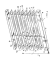
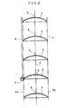
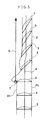
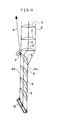
- Figs. 1 to 4 show a variable horizontal blind in accordance with one embodiment of the invention, and in the figure, reference numeral 1 denotes an upper box; 2, laddersupport cords; 3, a plurality of slats supported at given intervals in the vertical direction by the support cords 2.
- the front and rear edges of these slats 3 are fixed to front and rear vertical portions 2a and 2b of the support cords 2, respectively, in such a manner that the front and rear vertical portions 2a and 2b are relatively moved up and down, thereby allowing the slats 3 to tilt so as to come into an open state or in a close state to adjust light shielding.
- Reference numeral 12 denotes a lower box; 4, vertically moving cords for performing the open/close operation of the blind by making all the slats 3 move vertically; and 5, through-holes defined in the slats 3 for insertion of the vertically moving cords.
- variable horizontal blind is not fundamentally different from that of the conventional variable horizontal blind. Therefore, a means for operating the front vertical portion 2a and the rear vertical portion 2b of the support cords 2 for supporting the slats 3 and for allowing the slats 3 to tilt, and a means for operating the vertically moving cord 4 for rising and/or falling all he slats 3 are identical with those of the conventional variable horizontal blind, and therefore these operating means are omitted in Fig.1.
- Reference numeral 6 denotes lifting cords whose number depends upon the number of the support cords 2, and an lower end of each lifting cord 6 is fixed onto the front vertical portion 2a or the rear vertical portion 2b of each of the support cords 2 in the vicinity of the front or rear edge of a specified one of the slats 3, which is determined arbitrarily.
- the lower end of each support cord 2 may be directly fixed to the portions 2a or 2b by binding or the like, or it may be detachably fixed thereto through a fixed member 7 such as a fixed ring or the like.
- Each of the lifting cords 6 is put around each pulley 8 disposed on the upper box 1 in the vicinity of the upper end of each support cord 2 in such a manner that ends of the lifting cords 6 are taken out of one side of the upper box 1 so as to be hung, and the portion thus hung constitutes a pulling member (Fig. 1).
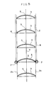
- Fig. 5 shows a variable horizontal blind in accordance with another embodiment of the invention.
- the lower ends of the lifting cords 6 are fixed onto the front vertical portion 2a and the rear vertical portion 2b of the support cords 2 in the vicinity of the front and rear edges of specified ones of the slats 3 which are determined arbitrarily.
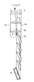
- Fig. 6 shows a variable horizontal blind in accordance with still another embodiment of the invention shown in Figs. 1 and 5, and in the embodiment, the lifting cords 6 pass through-holes 5 for insertion of vertically moving cords, which are defined in the slats 3 disposed above the portion 2a fixing the lower ends of the lifting cords 6.
- Fig. 8 shows a variable horizontal blind in accordance with still another embodiment of the invention.
- a means for operating each of the front vertical portion 2a, the rear vertical portion 2b and the vertically moving cord 4 is omitted as in Fig. 1.
- one end of the lifting cord 6 is properly fixed through a fixed member 10 onto the upper box 1 on or in the vicinity of the upper end side of any one of the front and rear vertical portions 2a and 2b of the support cords 2 disposed on one side in the lateral direction among the support cords 2-for supporting the slats 3.
- one end of the lifting cord 6 is fixed onto the upper box 1 in the vicinity of the upper end of the front vertical portion 2a of that support cord 2.
- a cord guide 11 on which the lifting cord 6 is freely hooked are movably fitted to a specified position of that support cords 2 determined arbitrarily in the vicinity of the front edge of the slats 3. Further, a cord guide 11 is likewise fitted to other support cords 2 at the same level, respectively, and other cord guides 11 are disposed on the upper box 1 in the vicinity of the upper end of the respective support cords 2.
- the lifting cord 6 whose one end is fixed onto the upper box 1 is hooked on the cord guide 11 fitted to the support cord 2 below the fixed member 10.
- the lifting cord 6 is hooked on the cord guide 11 of the adjacent support cord 2, it is hooked on the cord guide 11 disposed on the upper box 1 above that adjacent support cord 2.
- the lifting cord 6 is then hooked on the cord guide 11 disposed on the upper box 1 above the next support cord 2, and subsequently is hooked on the cord guide 11 fitted to the support cord 2 below that cord guide 11.
- the lifting cord 6 is hooked on the cord guide 11 disposed on the further adjacent support cord 2, and hooked on the cord guide 11 ofthe upper box 1 above the further adjacent support cord 2 in such a manner that the lifting cord 6 is successively hooked on the respective cord guides 11.
- the lifting cord 6 is hung on the cord guide 11 disposed on the upper box above- the support cord 2 at the other side of the blind with the result that the other end of the lifting cord 6 forms a pulling member 9.
- Figs. 9 and 10 show examples that a lifting cord 6 is hooked on cord guides 11 depending upon the number of the support cords 2, respectively.
- a pulley or ring is used as the cord guide 11.
- the kind of the guide 11 are not particularly limited.
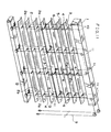
- Fig. 11 shows a variable horizontal blind in accordance with still another embodiment of the invention, in which a means for operating each of the front vertical portion 2a, the rear vertical portion 2b and the vertically moving cord 4 is omitted as in Fig. 1.
- one ends of the lifting cords 6 are fixed by the fixed members 10 to the upper box 1 in the vicinity of the upper ends of the front and rear vertical portions 2a and 2b of the support cords 2 located on one side in the lateral direction, respectively.
- the cord guides 11 are fitted to each of the support cords 2 in the vicinity of the front and rear edges of a specified one of the slats 3 which is determined arbitrarily and also to the upper box 1 in the vicinity of the upper end sides of the front vertical portion 2a and the rear vertical portion 2b of the support cords 2 located on the other side in the lateral direction, respectively in such a manner that the lifting cord 6 is successively hooked on from the cord guides 11 fitted on the respective support cords 2 to the cord guide 11 disposed on the upper box 1.
- the slats 3 stand in the close state, if the pulling member 9 fitted to one of the lifting cords 6 is pulled, then the slats 3 positioned below the cord guide 11 is tilted through the cord guides 11 on which the lifting cord 6 are hooked, thereby making the slats 3 in the open state.
- the slats 3 stand in the open state if one of the lifting cords 6 is pulled, then the slats 3 positioned below the cord guide 11 are tilted through the cord guides on which the pulled lifting cord 6 is hooked, thereby making the slats 3 in the open state.
- the lifting cord 6 may be inserted into a through-hole 5 which is defined in each of the slats 3 located above the cord guide 11, for insertion of the lifting cords, as in the embodiment shown in Fig. 6.
- a means for pulling the pulling member 9 which constitutes an free end of the lifting cord 11 may be of a manual means, an electric means or any other means. Further, there is considered, in the embodiment shown in Fig. 1, a method of winding the lifting cord 6 on a drum which is laterally equipped across the upper box 1, or in the embodiments shown in Figs. 8 and 11, a method of winding the pulling member 9 on the drum and rotating the drum from the exterior of the upper box 1. However, it is not limited to or by any means.
- the blind of the invention is remarkably useful as a variable horizontal blind, and further since the blind is simple in structure, the manufacture is facilitated and the blinds are obtained inexpensively.
Landscapes
- Engineering & Computer Science (AREA)
- Structural Engineering (AREA)
- Architecture (AREA)
- Civil Engineering (AREA)
- Blinds (AREA)
Applications Claiming Priority (2)
| Application Number | Priority Date | Filing Date | Title |
|---|---|---|---|
| JP12902/93 | 1993-03-22 | ||
| JP1290293U JPH0671888U (ja) | 1993-03-22 | 1993-03-22 | 可変式横形ブラインド |
Publications (1)
| Publication Number | Publication Date |
|---|---|
| EP0620355A1 true EP0620355A1 (fr) | 1994-10-19 |
Family
ID=11818309
Family Applications (1)
| Application Number | Title | Priority Date | Filing Date |
|---|---|---|---|
| EP94301855A Withdrawn EP0620355A1 (fr) | 1993-03-22 | 1994-03-14 | Jalousie horizontale variable |
Country Status (2)
| Country | Link |
|---|---|
| EP (1) | EP0620355A1 (fr) |
| JP (1) | JPH0671888U (fr) |
Cited By (8)
| Publication number | Priority date | Publication date | Assignee | Title |
|---|---|---|---|---|
| GB2304362A (en) * | 1995-08-22 | 1997-03-19 | Andrew Maxwell Goodwin | Venetian blind with groups of independently tiltable lamellae |
| EP0887507A3 (fr) * | 1997-06-24 | 2000-03-08 | Holis Metal Industries Ltd. | Mécanisme d'inclinaison pour un store vénitien |
| US6422288B1 (en) | 2000-05-19 | 2002-07-23 | Hunter Douglas Industries B.V. | Venetian blind with variable tilting |
| US6845802B1 (en) | 2001-08-15 | 2005-01-25 | Hunter Douglas Inc. | Selective tilting arrangement for a blind system for coverings for architectural openings |
| US7913738B2 (en) | 2005-09-02 | 2011-03-29 | Hunter Douglas Inc. | Selective tilting for blinds—variable radius wrap double pitch |
| US8267145B2 (en) | 2007-05-31 | 2012-09-18 | Hunter Douglas Inc. | Blind with selective tilting arrangement including drums |
| GB2516332A (en) * | 2013-04-22 | 2015-01-21 | Nien Made Entpr Co Ltd | Window covering |
| US9487996B2 (en) | 2012-02-27 | 2016-11-08 | Hunter Douglas Industries B.V. | Blind tilt assembly and method of controlling tilt ladders |
Families Citing this family (7)
| Publication number | Priority date | Publication date | Assignee | Title |
|---|---|---|---|---|
| JP2000337051A (ja) * | 1999-03-24 | 2000-12-05 | Akasaka Kogei Kk | ブラインド |
| WO2015163417A1 (fr) * | 2014-04-25 | 2015-10-29 | 立川ブラインド工業株式会社 | Store horizontal |
| JP6670540B2 (ja) * | 2014-08-11 | 2020-03-25 | 立川ブラインド工業株式会社 | 横型ブラインド |
| JP6961567B2 (ja) * | 2014-08-18 | 2021-11-05 | 立川ブラインド工業株式会社 | 電動横型ブラインド |
| JP6840509B2 (ja) * | 2016-10-31 | 2021-03-10 | 立川ブラインド工業株式会社 | 横型ブラインド |
| JP2020190176A (ja) * | 2019-05-14 | 2020-11-26 | 立川ブラインド工業株式会社 | 電動横型ブラインドおよび電動横型ブラインドシステム |
| JP2021011805A (ja) * | 2019-07-09 | 2021-02-04 | 立川ブラインド工業株式会社 | 電動横型ブラインド、並びに、コード支持ユニット及びリミットスイッチ |
Citations (3)
| Publication number | Priority date | Publication date | Assignee | Title |
|---|---|---|---|---|
| US2647572A (en) * | 1950-01-10 | 1953-08-04 | Percival H Biscoe | Venetian blind |
| US4621672A (en) * | 1985-01-18 | 1986-11-11 | Hsu Pei Shun | Mechanism for window blind |
| WO1992009779A1 (fr) * | 1990-11-23 | 1992-06-11 | Ctv S.R.L. | Dispositif servant a ouvrir et refermer des rideaux de fenetre a actionnement vertical et a course demultipliee |
Family Cites Families (1)
| Publication number | Priority date | Publication date | Assignee | Title |
|---|---|---|---|---|
| JPS5865891A (ja) * | 1981-10-12 | 1983-04-19 | 牧平 坦 | ブラインド |
-
1993
- 1993-03-22 JP JP1290293U patent/JPH0671888U/ja active Pending
-
1994
- 1994-03-14 EP EP94301855A patent/EP0620355A1/fr not_active Withdrawn
Patent Citations (3)
| Publication number | Priority date | Publication date | Assignee | Title |
|---|---|---|---|---|
| US2647572A (en) * | 1950-01-10 | 1953-08-04 | Percival H Biscoe | Venetian blind |
| US4621672A (en) * | 1985-01-18 | 1986-11-11 | Hsu Pei Shun | Mechanism for window blind |
| WO1992009779A1 (fr) * | 1990-11-23 | 1992-06-11 | Ctv S.R.L. | Dispositif servant a ouvrir et refermer des rideaux de fenetre a actionnement vertical et a course demultipliee |
Cited By (13)
| Publication number | Priority date | Publication date | Assignee | Title |
|---|---|---|---|---|
| GB2304362A (en) * | 1995-08-22 | 1997-03-19 | Andrew Maxwell Goodwin | Venetian blind with groups of independently tiltable lamellae |
| EP0887507A3 (fr) * | 1997-06-24 | 2000-03-08 | Holis Metal Industries Ltd. | Mécanisme d'inclinaison pour un store vénitien |
| US6076587A (en) * | 1997-06-24 | 2000-06-20 | Holis Metal Industries Ltd. | Tilting mechanism for a venetian blind |
| USRE43475E1 (en) | 2000-05-19 | 2012-06-19 | Hunter Douglas Industries Bv | Venetian blind with variable tilting |
| US6422288B1 (en) | 2000-05-19 | 2002-07-23 | Hunter Douglas Industries B.V. | Venetian blind with variable tilting |
| US6845802B1 (en) | 2001-08-15 | 2005-01-25 | Hunter Douglas Inc. | Selective tilting arrangement for a blind system for coverings for architectural openings |
| US7913738B2 (en) | 2005-09-02 | 2011-03-29 | Hunter Douglas Inc. | Selective tilting for blinds—variable radius wrap double pitch |
| US8485242B2 (en) | 2005-09-02 | 2013-07-16 | Hunter Douglas Inc. | Selective tilting for blinds including driven drums |
| US8267145B2 (en) | 2007-05-31 | 2012-09-18 | Hunter Douglas Inc. | Blind with selective tilting arrangement including drums |
| US9487996B2 (en) | 2012-02-27 | 2016-11-08 | Hunter Douglas Industries B.V. | Blind tilt assembly and method of controlling tilt ladders |
| US10156092B2 (en) | 2012-02-27 | 2018-12-18 | Hunter Douglas Industries B.V. | Blind tilt assembly and method of controlling tilt ladders |
| GB2516332A (en) * | 2013-04-22 | 2015-01-21 | Nien Made Entpr Co Ltd | Window covering |
| GB2516332B (en) * | 2013-04-22 | 2015-11-11 | Nien Made Entpr Co Ltd | Window covering |
Also Published As
| Publication number | Publication date |
|---|---|
| JPH0671888U (ja) | 1994-10-07 |
Similar Documents
| Publication | Publication Date | Title |
|---|---|---|
| EP0620355A1 (fr) | Jalousie horizontale variable | |
| KR101822678B1 (ko) | 횡형 블라인드 | |
| JP5713873B2 (ja) | 横型ブラインド | |
| JP6144306B2 (ja) | 横型ブラインド | |
| JPH0440396Y2 (fr) | ||
| JP5975835B2 (ja) | 横型ブラインド | |
| US2582301A (en) | Venetian blind | |
| US5316066A (en) | Cord-lock mechanism | |
| JP2781488B2 (ja) | 横型ブラインドのラダーコード及び横型ブラインド | |
| JP3583941B2 (ja) | プリーツスクリーン | |
| JP6082088B2 (ja) | 横型ブラインド | |
| JPH0128229Y2 (fr) | ||
| JPH044471Y2 (fr) | ||
| JP4856929B2 (ja) | 横型ブラインドのスラット角度調節装置 | |
| EP1413706A2 (fr) | Dispositif de manoeuvre pour stores vénitiens | |
| JPH0842268A (ja) | 上下独立型ブラインド | |
| JP3695693B2 (ja) | 日射遮蔽装置のボトムレール下限位置調整装置 | |
| JPH0128232Y2 (fr) | ||
| JP3695700B2 (ja) | 日射遮蔽装置の遮蔽材昇降装置 | |
| JP3660845B2 (ja) | ローマンシェード | |
| JPH0440395Y2 (fr) | ||
| JPH0455191Y2 (fr) | ||
| JPH0419194Y2 (fr) | ||
| JPH10184237A (ja) | 天窓用ブラインド | |
| JP3276590B2 (ja) | ヘッドボックス昇降型ブラインド |
Legal Events
| Date | Code | Title | Description |
|---|---|---|---|
| PUAI | Public reference made under article 153(3) epc to a published international application that has entered the european phase |
Free format text: ORIGINAL CODE: 0009012 |
|
| AK | Designated contracting states |
Kind code of ref document: A1 Designated state(s): DE FR GB |
|
| K1C1 | Correction of patent application (title page) published |
Effective date: 19941019 |
|
| STAA | Information on the status of an ep patent application or granted ep patent |
Free format text: STATUS: THE APPLICATION IS DEEMED TO BE WITHDRAWN |
|
| 18D | Application deemed to be withdrawn |
Effective date: 19950420 |