EP0620383A2 - Planetenreibgetriebe mit Zentrifugalkraftwirkung - Google Patents
Planetenreibgetriebe mit Zentrifugalkraftwirkung Download PDFInfo
- Publication number
- EP0620383A2 EP0620383A2 EP94110765A EP94110765A EP0620383A2 EP 0620383 A2 EP0620383 A2 EP 0620383A2 EP 94110765 A EP94110765 A EP 94110765A EP 94110765 A EP94110765 A EP 94110765A EP 0620383 A2 EP0620383 A2 EP 0620383A2
- Authority
- EP
- European Patent Office
- Prior art keywords
- friction
- pulleys
- internal
- friction pulleys
- external
- Prior art date
- Legal status (The legal status is an assumption and is not a legal conclusion. Google has not performed a legal analysis and makes no representation as to the accuracy of the status listed.)
- Withdrawn
Links
Images


Classifications
-
- F—MECHANICAL ENGINEERING; LIGHTING; HEATING; WEAPONS; BLASTING
- F16—ENGINEERING ELEMENTS AND UNITS; GENERAL MEASURES FOR PRODUCING AND MAINTAINING EFFECTIVE FUNCTIONING OF MACHINES OR INSTALLATIONS; THERMAL INSULATION IN GENERAL
- F16H—GEARING
- F16H13/00—Gearing for conveying rotary motion with constant gear ratio by friction between rotary members
- F16H13/06—Gearing for conveying rotary motion with constant gear ratio by friction between rotary members with members having orbital motion
-
- F—MECHANICAL ENGINEERING; LIGHTING; HEATING; WEAPONS; BLASTING
- F16—ENGINEERING ELEMENTS AND UNITS; GENERAL MEASURES FOR PRODUCING AND MAINTAINING EFFECTIVE FUNCTIONING OF MACHINES OR INSTALLATIONS; THERMAL INSULATION IN GENERAL
- F16H—GEARING
- F16H15/00—Gearings for conveying rotary motion with variable gear ratio, or for reversing rotary motion, by friction between rotary members
- F16H15/48—Gearings for conveying rotary motion with variable gear ratio, or for reversing rotary motion, by friction between rotary members with members having orbital motion
- F16H15/56—Gearings providing a discontinuous or stepped range of gear ratios
-
- F—MECHANICAL ENGINEERING; LIGHTING; HEATING; WEAPONS; BLASTING
- F16—ENGINEERING ELEMENTS AND UNITS; GENERAL MEASURES FOR PRODUCING AND MAINTAINING EFFECTIVE FUNCTIONING OF MACHINES OR INSTALLATIONS; THERMAL INSULATION IN GENERAL
- F16H—GEARING
- F16H1/00—Toothed gearings for conveying rotary motion
- F16H1/28—Toothed gearings for conveying rotary motion with gears having orbital motion
- F16H2001/2881—Toothed gearings for conveying rotary motion with gears having orbital motion comprising two axially spaced central gears, i.e. ring or sun gear, engaged by at least one common orbital gear wherein one of the central gears is forming the output
Definitions
- the adjacent pairs of frictional pulleys are respectively provided with frictional surfaces tapared in opposite direction, and between adjacent pairs of friction pulleys there is provided a spring so as to make the friction pulley have normal pressure for producing the friction force. Since the frictional coefficient is small, the spring force is normally greater than the frictional force by an order of magnitude, thus the load of the bearing for transmitting the spring forces is too great, the efficient is low, the transmission is heated and life is short. The relative slide friction between the frictional pulleys may aggravate such problems.
- the object of the invention is to overcome the deficiencies of the prior art and provide a mechanical variable speed drive having high efficiency, which can be shifted without cutting out the load.
- the invention provides a centrifugal planetary friction transmission comprising an input shaft, an output shaft, at least a rotating arm, at least one irrotational internal friction pulley, at least one rotatable internal friction pulley, at least one set of linked planetary external friction pulleys rotating about its axis and orbiting about an axis of the internal friction pulleys, said at least one set of external friction pulleys having radially floating means so as to float radially and to engage with said internal friction pulleys under the action of centrifugal force, characterized in that only one of said irrotational internal friction pulleys and one of said rotatable internal friction pulleys engage with said external friction pulleys during transmitting, said one of rotatable internal friction pulleys outputting the power, said planetary external friction pulleys being at least a set of external friction pulleys which is formed by at least three coaxially linked cylindrical external pulleys
- Said internal friction pulleys and said external friction pulleys are preferably disposed to make the distance between the centres of said internal friction pulley and said external friction pulley which are engaged is unchanged through said slide along the axial direction thus the eccentric distance of said planetary friction pulleys being unchanged before and after the shift.
- both the side of said rotatable internal friction pulleys and the side of said irrotational internal friction pulleys there are provided a certain pair of separable friction pulleys and both said rotatable internal friction pulleys and said irrotational internal friction pulleys are axially slidable relative to said planetary external friction pulleys so that the separating or engagement of any pair of separable friction pulleys causes a change of the transmission ratio of the transmission and the total number of shifting speed ratio is a product of the number of separable friction pulley pairs on the side of rotatable internal friction pulleys and the number of separable friction pulley pairs on the side of irrotational internal friction pulleys.
- K pairs of separable friction pulley pairs are disposed respectively on both the side of irrotational internal friction pulleys and the side of rotatable internal friction pulleys, the separable friction pulleys pairs on both the side of rotatable internal friction pulleys and the side of irrotational internal friction pulleys being able to separate or engage so as to change the transmission ratio of the transmission, and such an axial slide at both sides of rotatable and irrotation internal friction pulleys changing the distance between the centers of the friction pulleys which are engaged, so that the eccentric distance of the planetary friction pulleys may change through the shift, and the number of shifting speed ratio is K.
- the transmission further comprises other separable friction pulley pairs, of which the accentric distance is unchanged through shifting, and which are disposed at either the side of rotatable friction pulleys or the side of irrotatable friction pulleys to obtain more variable speed ratio through the separation or engagement of friction pulley pairs by ralative axial slide.
- the transmission may further comprise a helical gear pair, of which the internal and external gear connect respectively with an input shaft and an output shaft of the gear pair, and a compression spring being disposed between the side surface of the external gear and the internal gear, the input shaft of the gear pair being axial slidable, the helical gear pair transmitting the torque of said transmission when the torque is changed, the engaging axial force of the helical gear pair being changed and put into a coaction with the compression spring to move axially the axial slidable gear shaft so as to move axially the relative parts of the transmission to change the transmission ratio.
- At least one friction pulley pair have a diameter which are so determined as to make the output shaft backrun so that the transmission has a reverse shift.
- the transmission further comprises a freely rotatable internal friction pulley or external friction pulley which does not contact with other elements, when it enters into friction contact, the speed variator is located in an idle position.
- the friction pulleys of said separable friction pulleys pair may have edges of contact sides with larger chamfer or curved surface so as to make the friction pulley pairs come easily into contact.
- the transmission according to the invention uses a great centrifugal force produced by the planetary friction pulleys to be rotated at high speed themselves for the normal pressure so that the bearings bear no normal pressure, and no relative slip friction is produced between the friction pulleys, thus the effeciency, the life and the output torque moment are greatly increased.
- Figure 1 shows a conventional friction pulleys transmission having a fixed speed radio. Said transmission is of double internal contact type. External-friction pulleys 7, 8 and 7', 8' are coaxially and fixedly connected with each other respectively to form two duplex planet friction pulley sets with same structures. They are supported by the rotating arm 5 via the shaft through the planet bearings 6. The rotating arm 5 connects fixedly with the input shaft 4 to keep the axle of each duplex planet friction pulley set parallel to the axle of input shaft and the distance between the axle of the pulley and the axle of the input shalt (eccentric distance) for both pulleys sets equal. The input shaft 4 is supported by the left housing 13 and the output shaft 10 by means of bearings 15, 14.
- the output shaft 10 is supported by right housing 11.
- the rotation arm 5 drives both the duplex planet friction pulley sets to orbit.
- the external friction pulleys 7, 7' rotate and are forced towards the inner circumference of the internal-friction pulley 12 under the action of centrifugal force.
- the coaction of orbit and rotation makes external-friction pulleys 8, 8' drive the internal-friction pulley 9 to rotate at a low speed, thus the centrifugal planetary friction drive is established.
- the centrifugal planetary friction transmission of this invention is used for shifting transmission.
- double internal-contact means see Fig. 1
- shifting modes there are two kinds of shifting modes to meet the condition of equal eccentric distance.
- the first mode keeps the eccentric distance constant with changing simultaneously the value of r1, r2 and/or r3, r4, wherein r1-radio of the external pulley of the first friction pulley pair, r2-radio of the internal pulley of the first friction pulley pair, r3-radio of the external pulley of the second friction pulley pair, and r4-radio of the internal pulley of the second friction pulley pair.
- the second mode makes eccentric distance vary companying changing the values of r1, r3 and/or r2, r4.
- External -friction pulley 37 contacts with the rotatable internal friction pulley 41 formed integrally with the input shaft.
- Internal-friction pulley 41 is supported by right housing 47.
- Internal-friction pulleys 38, 39 are linked up coaxially to form a double internal-friction pulley set whose external circumference is provided slidingly inside left housing 40.
- the double friction pulley may slide axially with the aid of a key but it can not rotate. In the position shown in Fig. 2 the inner circumference of internal-friction pulley 38 contacts with planet friction pulley 35.
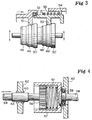
- the edge of contact sides of the friction pulleys of all separable friction pulley pairs should have larger chamfer and transits smoothly with inclined plane or curved surface (see right side of external-friction pulley 35 and internal-friction pulley 39 and left side of external-friction pulley 36 and internal-friction pulley 38, as shown in Fig. 2, also the left side of the six outer friction pulleys shown in Fig. 3 ).
- Fig. 3 is a partial sectional view in which the portions having nothing to do with the feature of the structure have been deleted.
- External-friction pulleys 48, 49, 50, 48', 49', 50' are linked up coaxially to form a hexad planet friction pulley set.
- Internal friction pulley 51 which can not rotate connects to rotatable internal-friction pulley 53 through bearing 52.
- the compression spring 55 is disposed between pulley 53 and housing 54. Friction pulleys 51, 53 with the bearing 52 therebetween may slide axially as shown by the horizontal arrow, they move leftward under the action of the force of spring 55 or move rightward under the action of external thrust.
- the hexad planet friction pulley set may remove radially. That is to say they move upward under the action of centrifugal force or move downward under a force caused by internal-friction pulleys when the latter are move rightward, thus the eccentric distance is also changed. Accordingly, the radially floating means should have larger sliding path.
- pulley 51 contacts with pulley 49, pulley 53 with pulley 49', and the transmission has a determined speed ratio.
- pulley 51, 53 and the bearing 52 therebetween move leftward, pulley 51 contacts with pulley 48, pulley 53 with pulley 48'.
- the shifting function may be also obtained through other way in which the external-friction pulley may slide axially while internal-friction pulley is immobile axially.
- the combination of double or multiple internal-friction pulley set (rotatable as well as irrotational) shown in Fig. 2 and multiple planet friction pulley set which may slide axially can obtain more variable speed ratios and wide shifting range.
- the centrifugal planetary friction transmission of this invention may conveniently obtain more variable speed ratios and wide shifting range and may be speed-changed smoothly and easily during operation, it may be adopted to form a "quasi-stepless speed variator" so that it can be used more extensively, for example in the transmission system of automobile.
- a "quasi-stepless speed variator” used in an automobile in addition to more variable speed ratio it is necessary that the means can shift automatically according to the load so as to obtain constant input power characteristic.
- an automatically shifting means shown in Fig. 4 can be used.
- External-cylindrical helical gear 56 engages with internal-cylidrical helical gear (to form a gear shaft coupling when they have same number of teeth).
- Both gears may slide relatively to the direction of axis.
- the axial force resuting form engagement of said helical gears pushes gear 56 to slide rightward as shown in Fig. 4, the compression spring 61 pushes gear 56 to slide leftward as shown by the horizontal arrow.
- the shaft 64 linked with gear 56 is supported on frame 62 by journal 63 through bearing bushing 60, it drives gear 56 to rotate and transfers the axial force from gear 56.
- Shaft 64 may be formed integrally with rotatable internal-friction pulley in above-mentioned shifting means and may directly transfer the axial force to the internal-friction pulley which may axially slide but is irrotational (as shown by 38-39 in Fig. 2 and 51 in Fig. 4).
- the quasi-stepless speed variator of this invention may have concurrently both advantages of current hydraulic torue converter (shifting smoothly, having self-adaptability, absorbing shock and prolonging life of drive system) and the advantages of current gearbox (small volume, simple structure, and high driving efficiency). Moreover, it further has unique advantages such as overload protection (protecting engine from extinction), low noise, enabling engine to start under loading.
- the centrifugal planetary friction transmission of this invention has further excellent starting property in addition to above-mentioned advantages. Since the friction force is set up gradually depending on arising rotating speed and increasing centrifugal force, and it further has the property of hydrodynamic clutch, the prime mover does not subject load during starting. Thus the prime mover does not subject load during starting. Thus the prime mover such as electric motor has excellent starting characteristic under heavy load. To sum up, it can be expected that in high-speed power transmission field the centrifugal planetary friction transmission of this invention will be substituted for gear transmission.
Landscapes
- Engineering & Computer Science (AREA)
- General Engineering & Computer Science (AREA)
- Mechanical Engineering (AREA)
- Friction Gearing (AREA)
- Transmission Devices (AREA)
- Retarders (AREA)
- Transmissions By Endless Flexible Members (AREA)
- Pulleys (AREA)
Applications Claiming Priority (3)
| Application Number | Priority Date | Filing Date | Title |
|---|---|---|---|
| CN90104953 | 1990-07-25 | ||
| CN 90104953 CN1058460A (zh) | 1990-07-25 | 1990-07-25 | 离心式摩擦行星传动 |
| EP19910112531 EP0468511B1 (de) | 1990-07-25 | 1991-07-25 | Planetenreibgetriebe mit Zentrifugalkraftwirkung |
Related Parent Applications (1)
| Application Number | Title | Priority Date | Filing Date |
|---|---|---|---|
| EP91112531.8 Division | 1991-07-25 |
Publications (2)
| Publication Number | Publication Date |
|---|---|
| EP0620383A2 true EP0620383A2 (de) | 1994-10-19 |
| EP0620383A3 EP0620383A3 (de) | 1995-03-29 |
Family
ID=4878819
Family Applications (2)
| Application Number | Title | Priority Date | Filing Date |
|---|---|---|---|
| EP94110765A Withdrawn EP0620383A3 (de) | 1990-07-25 | 1991-07-25 | Planetenreibgetriebe mit Zentrifugalkraftwirkung. |
| EP19910112531 Expired - Lifetime EP0468511B1 (de) | 1990-07-25 | 1991-07-25 | Planetenreibgetriebe mit Zentrifugalkraftwirkung |
Family Applications After (1)
| Application Number | Title | Priority Date | Filing Date |
|---|---|---|---|
| EP19910112531 Expired - Lifetime EP0468511B1 (de) | 1990-07-25 | 1991-07-25 | Planetenreibgetriebe mit Zentrifugalkraftwirkung |
Country Status (6)
| Country | Link |
|---|---|
| EP (2) | EP0620383A3 (de) |
| JP (1) | JPH04236844A (de) |
| CN (1) | CN1058460A (de) |
| AU (2) | AU653737B2 (de) |
| CA (1) | CA2047894A1 (de) |
| DE (1) | DE69113352D1 (de) |
Cited By (1)
| Publication number | Priority date | Publication date | Assignee | Title |
|---|---|---|---|---|
| US6342023B1 (en) | 1997-07-15 | 2002-01-29 | Aimbridge Pty Ltd. | Gear profile for orbital gear transmissions, and orbital gear transmission and winches utilizing orbital gear transmissions |
Families Citing this family (19)
| Publication number | Priority date | Publication date | Assignee | Title |
|---|---|---|---|---|
| DE19626403A1 (de) * | 1996-07-01 | 1998-01-08 | Heinzl Joachim | Umlauf-Reibradgetriebe |
| WO2001036842A1 (en) * | 1999-11-15 | 2001-05-25 | Nidec Copal Corporation | Speed reduction gear |
| DE10110644A1 (de) * | 2001-03-06 | 2002-09-19 | Alpha Getriebebau Gmbh | Planetengetriebe |
| CN102734409A (zh) * | 2012-05-21 | 2012-10-17 | 赵会文 | 一种行星传动及其形成的可形成无级变速器的行星传动 |
| WO2015113163A1 (en) | 2014-01-30 | 2015-08-06 | Genesis Advanced Technology Inc. | Roller drive |
| CN106763620A (zh) * | 2015-11-20 | 2017-05-31 | 张秘来 | 一种行星轮滚动摩擦传动装置 |
| CN105698123B (zh) * | 2016-03-16 | 2018-06-08 | 上海交通大学 | 仿行星运动的吊灯 |
| CN105971439B (zh) * | 2016-06-24 | 2018-01-16 | 合肥华凌股份有限公司 | 开门电机组件、自动开门系统及工作方法、冰箱 |
| WO2019051614A1 (en) | 2017-09-16 | 2019-03-21 | Genesis Advanced Technology Inc. | DIFFERENTIAL PLANETARY TRAIN GEARBOX |
| CN110269778B (zh) * | 2019-06-30 | 2021-10-29 | 王卫松 | 一种骨科病人腿部康复训练装置 |
| CN110269777B (zh) * | 2019-06-30 | 2021-09-28 | 洛阳市中心医院 | 用于骨科下肢术后助力运动的训练装置 |
| CN111396518A (zh) * | 2020-04-30 | 2020-07-10 | 北京瑞昌同创机电科技有限公司 | 行星离心式无级传动机构及其控制方法 |
| CN112984065B (zh) * | 2021-03-02 | 2022-04-08 | 中国科学院宁波材料技术与工程研究所 | 一种基于摩擦传动的双排行星减速器 |
| CN113546768A (zh) * | 2021-08-17 | 2021-10-26 | 芦育莹 | 一种离心力输出装置 |
| CN114483934A (zh) * | 2022-01-25 | 2022-05-13 | 王国富 | 一种多联行星齿轮变速装置自动变速方法及其变速装置 |
| CN114516067B (zh) * | 2022-03-09 | 2024-05-31 | 清华大学 | 绳索驱动切换装置及其绳驱机械臂 |
| CN115773344A (zh) * | 2022-11-18 | 2023-03-10 | 扬州工业职业技术学院 | 一种自动加载变速器及自动加载变速方法 |
| CN116357709A (zh) * | 2023-02-23 | 2023-06-30 | 东北大学秦皇岛分校 | 一种轮轴式无级变速器 |
| CN120042896B (zh) * | 2025-04-27 | 2025-06-27 | 云南红盛元机电技术发展有限公司 | 滚针运动旋转传动机构 |
Family Cites Families (12)
| Publication number | Priority date | Publication date | Assignee | Title |
|---|---|---|---|---|
| DE128899C (de) * | ||||
| FR764483A (fr) * | 1933-02-08 | 1934-05-22 | Réducteur de vitesse à grande démultiplication | |
| US2495470A (en) * | 1946-05-23 | 1950-01-24 | Joseph J Mascuch | Variable-speed drive |
| FR1049544A (fr) * | 1950-11-11 | 1953-12-30 | Philips Nv | Accouplement entre un arbre moteur et un arbre mené |
| GB923508A (en) * | 1959-04-16 | 1963-04-10 | Fichtel & Sachs Ag | Improvements in eccentric transmissions |
| JPS4872556A (de) * | 1971-12-29 | 1973-09-29 | ||
| US3889554A (en) * | 1974-01-09 | 1975-06-17 | Brett Jason Sinclair | Roller transmission |
| JPS50138259A (de) * | 1974-04-22 | 1975-11-04 | ||
| US4499781A (en) * | 1982-06-01 | 1985-02-19 | Lew Hyok S | Chamfered roller mechanical transmission |
| JPS5929864A (ja) * | 1982-08-10 | 1984-02-17 | Matsushita Electric Works Ltd | 遊星減速機 |
| JPS6078151A (ja) * | 1983-10-03 | 1985-05-02 | Otaru Seisakusho:Kk | 遊星変速機 |
| FR2599802B1 (fr) * | 1986-06-06 | 1988-08-26 | Fuminier Claude | Reducteur sans jeu pour notamment articulations de bras manipulateurs |
-
1990
- 1990-07-25 CN CN 90104953 patent/CN1058460A/zh active Pending
-
1991
- 1991-07-25 DE DE69113352T patent/DE69113352D1/de not_active Expired - Lifetime
- 1991-07-25 EP EP94110765A patent/EP0620383A3/de not_active Withdrawn
- 1991-07-25 AU AU81350/91A patent/AU653737B2/en not_active Ceased
- 1991-07-25 CA CA 2047894 patent/CA2047894A1/en not_active Abandoned
- 1991-07-25 JP JP18651491A patent/JPH04236844A/ja active Pending
- 1991-07-25 EP EP19910112531 patent/EP0468511B1/de not_active Expired - Lifetime
-
1994
- 1994-05-04 AU AU61871/94A patent/AU664514B2/en not_active Ceased
Cited By (1)
| Publication number | Priority date | Publication date | Assignee | Title |
|---|---|---|---|---|
| US6342023B1 (en) | 1997-07-15 | 2002-01-29 | Aimbridge Pty Ltd. | Gear profile for orbital gear transmissions, and orbital gear transmission and winches utilizing orbital gear transmissions |
Also Published As
| Publication number | Publication date |
|---|---|
| JPH04236844A (ja) | 1992-08-25 |
| CN1058460A (zh) | 1992-02-05 |
| CA2047894A1 (en) | 1992-01-26 |
| EP0620383A3 (de) | 1995-03-29 |
| AU653737B2 (en) | 1994-10-13 |
| AU664514B2 (en) | 1995-11-16 |
| AU8135091A (en) | 1992-01-30 |
| DE69113352D1 (de) | 1995-11-02 |
| EP0468511B1 (de) | 1995-09-27 |
| AU6187194A (en) | 1994-07-07 |
| EP0468511A1 (de) | 1992-01-29 |
Similar Documents
| Publication | Publication Date | Title |
|---|---|---|
| EP0620383A2 (de) | Planetenreibgetriebe mit Zentrifugalkraftwirkung | |
| US5230670A (en) | Friction roller type continuously variable transmission | |
| US4467670A (en) | Belt drive continuously-variable speed automatic transmission | |
| US4189960A (en) | Underdrive transmission with sun gear and carrier slidable as a subassembly | |
| US4973288A (en) | Belt drive continuously variable speed transmission | |
| US4740191A (en) | Power transmission system | |
| US6517461B2 (en) | Infinitely variable transmission | |
| US4484493A (en) | Cone pulley V-belt continuously variable transmission | |
| EP0416492B1 (de) | Stufenloses Getriebe | |
| US4864891A (en) | Power transmission system | |
| US5425283A (en) | Multi-speed power transmission | |
| US5372555A (en) | Continuously variable traction roller transmission | |
| US6117037A (en) | Toroidal continuous variable transmission | |
| US4005609A (en) | Automatic variable speed transmission | |
| US6189397B1 (en) | Multi-speed automotive transmission using paired helical gearing | |
| GB2313424A (en) | Toroidal continuously- variable transmission | |
| US4184385A (en) | Output split-type mechanical and hydraulic transmission | |
| JPH1182660A (ja) | 無段変速機の潤滑構造 | |
| RU2068516C1 (ru) | Коробка передач | |
| KR0174168B1 (ko) | 무단 변속장치 | |
| JPS61103055A (ja) | トロイダル形無段変速機 | |
| GB2038963A (en) | An Integral Engine and Transmission Unit for a Power Boat | |
| JPH0318768Y2 (de) | ||
| JP2831886B2 (ja) | 湿式機械式の無段変速機 | |
| Kemper | A High Power Density Traction Drive |
Legal Events
| Date | Code | Title | Description |
|---|---|---|---|
| PUAI | Public reference made under article 153(3) epc to a published international application that has entered the european phase |
Free format text: ORIGINAL CODE: 0009012 |
|
| AC | Divisional application: reference to earlier application |
Ref document number: 468511 Country of ref document: EP |
|
| AK | Designated contracting states |
Kind code of ref document: A2 Designated state(s): CH DE FR GB IT LI SE |
|
| PUAL | Search report despatched |
Free format text: ORIGINAL CODE: 0009013 |
|
| PUAF | Information related to the publication of a search report (a3 document) modified or deleted |
Free format text: ORIGINAL CODE: 0009199SEPU |
|
| PUAL | Search report despatched |
Free format text: ORIGINAL CODE: 0009013 |
|
| AK | Designated contracting states |
Kind code of ref document: A3 Designated state(s): CH DE FR GB IT LI SE |
|
| D17D | Deferred search report published (deleted) | ||
| AK | Designated contracting states |
Kind code of ref document: A3 Designated state(s): CH DE FR GB IT LI SE |
|
| 17P | Request for examination filed |
Effective date: 19951018 |
|
| 17Q | First examination report despatched |
Effective date: 19960823 |
|
| STAA | Information on the status of an ep patent application or granted ep patent |
Free format text: STATUS: THE APPLICATION IS DEEMED TO BE WITHDRAWN |
|
| 18D | Application deemed to be withdrawn |
Effective date: 19970102 |