EP0620476B1 - Système d'illumination photographique mettant en oeuvre un posemètre pour lumière d'incidence - Google Patents
Système d'illumination photographique mettant en oeuvre un posemètre pour lumière d'incidence Download PDFInfo
- Publication number
- EP0620476B1 EP0620476B1 EP94420085A EP94420085A EP0620476B1 EP 0620476 B1 EP0620476 B1 EP 0620476B1 EP 94420085 A EP94420085 A EP 94420085A EP 94420085 A EP94420085 A EP 94420085A EP 0620476 B1 EP0620476 B1 EP 0620476B1
- Authority
- EP
- European Patent Office
- Prior art keywords
- light
- fill
- electric
- subject
- camera
- Prior art date
- Legal status (The legal status is an assumption and is not a legal conclusion. Google has not performed a legal analysis and makes no representation as to the accuracy of the status listed.)
- Expired - Lifetime
Links
- 230000035945 sensitivity Effects 0.000 claims description 31
- 230000004044 response Effects 0.000 claims description 14
- 238000000034 method Methods 0.000 claims description 10
- 230000007935 neutral effect Effects 0.000 claims description 3
- 230000008878 coupling Effects 0.000 claims description 2
- 238000010168 coupling process Methods 0.000 claims description 2
- 238000005859 coupling reaction Methods 0.000 claims description 2
- 230000003287 optical effect Effects 0.000 claims 4
- 230000003213 activating effect Effects 0.000 claims 1
- 238000005286 illumination Methods 0.000 description 9
- 238000010586 diagram Methods 0.000 description 3
- 230000000694 effects Effects 0.000 description 3
- 230000001276 controlling effect Effects 0.000 description 2
- 230000007423 decrease Effects 0.000 description 2
- 230000002411 adverse Effects 0.000 description 1
- 238000001514 detection method Methods 0.000 description 1
- 230000001815 facial effect Effects 0.000 description 1
- 210000001061 forehead Anatomy 0.000 description 1
- 230000006872 improvement Effects 0.000 description 1
- 230000007246 mechanism Effects 0.000 description 1
- 230000004048 modification Effects 0.000 description 1
- 238000012986 modification Methods 0.000 description 1
- 210000003739 neck Anatomy 0.000 description 1
- 210000004279 orbit Anatomy 0.000 description 1
- 238000004806 packaging method and process Methods 0.000 description 1
- 230000001105 regulatory effect Effects 0.000 description 1
- 230000000007 visual effect Effects 0.000 description 1
- 230000037303 wrinkles Effects 0.000 description 1
Images

Classifications
-
- G—PHYSICS
- G03—PHOTOGRAPHY; CINEMATOGRAPHY; ANALOGOUS TECHNIQUES USING WAVES OTHER THAN OPTICAL WAVES; ELECTROGRAPHY; HOLOGRAPHY
- G03B—APPARATUS OR ARRANGEMENTS FOR TAKING PHOTOGRAPHS OR FOR PROJECTING OR VIEWING THEM; APPARATUS OR ARRANGEMENTS EMPLOYING ANALOGOUS TECHNIQUES USING WAVES OTHER THAN OPTICAL WAVES; ACCESSORIES THEREFOR
- G03B7/00—Control of exposure by setting shutters, diaphragms or filters, separately or conjointly
- G03B7/16—Control of exposure by setting shutters, diaphragms or filters, separately or conjointly in accordance with both the intensity of the flash source and the distance of the flash source from the object, e.g. in accordance with the "guide number" of the flash bulb and the focusing of the camera
-
- G—PHYSICS
- G03—PHOTOGRAPHY; CINEMATOGRAPHY; ANALOGOUS TECHNIQUES USING WAVES OTHER THAN OPTICAL WAVES; ELECTROGRAPHY; HOLOGRAPHY
- G03B—APPARATUS OR ARRANGEMENTS FOR TAKING PHOTOGRAPHS OR FOR PROJECTING OR VIEWING THEM; APPARATUS OR ARRANGEMENTS EMPLOYING ANALOGOUS TECHNIQUES USING WAVES OTHER THAN OPTICAL WAVES; ACCESSORIES THEREFOR
- G03B15/00—Special procedures for taking photographs; Apparatus therefor
- G03B15/02—Illuminating scene
- G03B15/03—Combinations of cameras with lighting apparatus; Flash units
- G03B15/05—Combinations of cameras with electronic flash apparatus; Electronic flash units
Definitions
- This invention relates to a photographic lighting system for use with a camera and, more particularly, to a photographic lighting system wherein shadows are alleviated by providing a fill light that increases in intensity as the incident light intensity increases.
- Most indoor spaces that are designed for human activity include artificial electric illumination to a level of at least 323 candelas/m 2 (30 footcandles), with most work areas illuminated to 646 candelas/m 2 (60 footcandles) or more. This level of illumination is quite sufficient for all modern film and video cameras, which can record an image with 108 cd/m 2 (10 footcandles) or less.
- Video camera manufacturers often encourage users to create video programs using nothing more than the available illumination. The video images thus created are usually quite unacceptable due to the fact that the available illumination is almost always in the form of ceiling or overhead lights. This type of illumination creates shadows on the face, dark eye sockets and black necks, and accentuates facial wrinkles. Furthermore, the forehead, nose and shoulders are significantly overbright and appear to be glowing. Thus, the available overhead light is often unacceptable for foreground subjects.
- a reflective light metering device has been incorporated into lights for home video cameras.
- the metering device determines the amount of light reflected off the subject in order to increase the output of the camera's onboard light in low light and to decrease the output in bright light. This is usually accomplished by a variable resistance in series with the light, which increases or decreases the voltage applied to the light bulb.
- US- 4,666,280 discloses a flash unit wherein the degree of concentration of flash lighting is varied responsive to detection of a backlight situation.
- the concentration of the flash unit light is increased when the backlighting increases so as to match foreground subject illumination with the background.
- US- 4,959,755 discloses a video camera including a light sensor for sensing ambient light and reflected radiant light from a scene. The lamp intensity is lowered when the ambient light level increases.
- This patent discusses US- 4,368,406 in which a light control includes an ambient light sensor wherein the light is raised and lowered in concert with the ambient light. The light control is for use with a lighted control panel for a vehicle or the like.
- US- 4,587,457 discloses a multiple-intensity controller with variable impedance which is responsive to ambient light levels and may be used to increase the output intensity with increases in ambient light levels. Use with a camera is not disclosed.
- US- 3,962,600 discloses a control circuit wherein ambient light is sensed and the light of a clock is controlled.
- the clock light is increased in intensity in concert with increases in the ambient light.
- US- 5,049,916 discloses exposure control apparatus and methods for use in a photographic camera to improve the overall quality of photographed images over the obtainable by adherence to ISO/ANSI exposure standards.
- the quality improvement is attained through automatic selection of photographic exposure parameters primarily based upon scene requirements (including providing sufficient depth-of-field and voiding image blur) and film exposure characteristics, rather through the use of the ISO/ANSI exposure standards.
- EP-A- 0,066,383 discloses a photographic exposure control system of the type for controlling both the duration of a photographic exposure interval and the amount of artificial illumination provided during the exposure interval.
- the control system includes the capability of increasing the amount artificial illumination in direct corresponding relation with increases in the camera-to-subject distance and the ambient scene light intensity in order to maintain the same proportions between the contributions to the film exposure from the ambient and from the artificial light during a fill flash exposure.
- the lighting apparatus provides fill-in light from the direction of the camera to alleviate shadows in a photographic image.
- a photographic lighting apparatus for use with a camera according to the invention comprises the features defined by claim 1.
- the photographic lighting apparatus for use with a camera comprises the features defined by claim 2.
- the sensing means can comprise an incident light meter adapted for mounting on the camera so as to sense incident light from above the camera.
- the incident light on the camera is approximately equal to the incident light on the subject.
- the means for generating a distance input can comprise means for sensing the distance, means for manually adjusting the distance input or means for coupling the distance input from the camera.
- the sensitivity input is representative of the sensitivity of the camera, or for specific "fine tuning" of the lighting ratio, or compensation for the efficiency of a particular set of bulbs.
- the fill light intensity at the subject is compensated for the sensitivity of the camera, or bulb efficiency.
- the electric light means can comprise a plurality of electric lamps.
- the control circuit means includes means for varying the average power supplied to the electric light means, such as by pulse width modulation.
- the electric light means comprises one or more electric lamps and means for attenuating the light output of the electric lamps in response to the control signal. A predetermined fill light intensity is provided by energizing a selected number of the electric lamps.
- a method of photographic lighting for use with a camera comprises the steps as claimed in claim 14.
- a method of photographic lighting for use with a camera comprises the steps as claimed in claim 15.
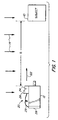
- FIG. 1 A schematic representation of a camera using a photographic lighting system in accordance with the present invention is shown in FIG. 1.
- a subject 10 is to be photographed by a camera 12.
- camera refers to either a video camera or a film camera.
- Incident light as indicated by arrows 14, illuminates subject 10 from above.
- the incident light is typically provided by overhead or ceiling lighting.
- the incident light is assumed to be sufficient for use of the camera. However, the incident light from above produces objectionable shadows in photographic images obtained by camera 12.
- a photographic lighting system 20 provides fill light as indicated by arrow 22 from the direction of camera 12 to alleviate shadows in the photographic images obtained by camera 12.
- the photographic lighting system includes an electric light unit 24, an incident light sensor 26 and a control circuit 28.
- the light unit 24 and light sensor 26 are interconnected to control circuit 28 by an electrical cable 29.
- the electric light unit 24, the incident light sensor 26 and the control circuit 28 can be packaged separately as shown in FIG. 1, together in one unit, or in any other suitable packaging arrangement, within the scope of the present invention.
- the photographic lighting system 20 can be mounted on camera 12 or can be a separate unit. It is preferred for convenience of use that the photographic lighting system 20 be mounted on camera 12.
- the incident light sensor 26 can be a photocell or similar light sensing device.
- the incident light sensor 26 is directed upwardly so as to receive incident light from above. It is assumed that the intensity of incident light at the camera location is approximately the same as the intensity of incident light at the subject location.
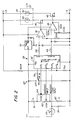
- a resistor 30 is connected in series with the incident light sensor 26 between a voltage +V and reference voltage -E or ground.
- the incident light sensor 26 is connected to an analog input of a microcontroller 32.
- the microcontroller 32 can be of the type that includes analog-to-digital converters so that analog input voltages can be connected directly to the device.
- One example of a suitable microcontroller is a type 87C752 manufactured by Signetics.
- a first output of the microcontroller 32 is connected through a resistor 34 to an input of a level shift circuit 36, which can be type LM-358.
- the output of level shift circuit 36 is connected to the gate of a MOS FET transistor 48.
- the drain of transistor 38 is connected to a lamp 40 of light unit 24.
- the source of transistor 38 is connected to a reference voltage -E or ground.
- a second output of microcontroller 32 is connected through a similar circuit including resistor 44, level shift circuit 46 and MOS FET transistor 48.
- the drain of transistor 48 is connected to a lamp 50 of light unit 24.
- microcontroller 32 energizes one, both or neither of lamps 40 and 50 to provide a desired fill light intensity.
- the fill light intensity depends in part on the sensed intensity of incident light as described below.
- a second input to microcontroller 32 is a distance input, which represents the distance D between light unit 24 and subject 10. Since the intensity of fill light at subject 10 is inversely proportional to the square of the distance D, the output of light unit 24 must be adjusted to compensate for the distance D between light unit 24 and subject 10.
- the distance input to microcontroller 32 can be derived from any suitable source of a distance indicating signal. Examples include a distance signal from an autofocus system of camera 12, a mechanical or electronic linkage to the focus mechanism of the lens in camera 12, a distance sensor such as an ultrasonic or infrared distance sensor, or a manual input for estimated or measured distance.
- the circuit shown in the embodiment of FIG. 2 utilizes a potentiometer 60 to provide a manually-adjustable distance input signal.
- the potentiometer 60 is connected in series with resistors 61 and 62 between supply voltages +V and -E.
- the distance input is connected to one of the analog inputs of microcontroller 32.
- a third input to microcontroller 32 is a sensitivity control input from a potentiometer 64.
- the potentiometer 64 is connected in series with resistors 61 and 62 between supply voltages +V and -E.
- the sensitivity control input adjusts the fill light provided by the lighting system to match a specific camera.
- the sensitivity control can be used to fine tune the other inputs to the microcontroller 32 in order to compensate for the variances in sensitivity among video and film cameras.
- the operator should only be required to set the sensitivity once by noting the visual results in the viewfinder of the camera 12. However, the operator can also use the sensitivity control to fine tune the light output at any time for creative effect or for any other reason.
- the sensitivity control input is connected to one of the analog inputs of microcontroller 32.
- Power is typically supplied to the photographic lighting system 20 from a battery in the form of a positive voltage +E and a negative voltage -E.
- Positive voltage +E is supplied to lamps 40 and 50, to level shift circuits 36 and 46 and to a voltage regulator 70.
- the voltage regulator 70 provides a regulated voltage +V to the microcontroller 32, incident light sensor 26 and potentiometers 60 and 64.
- the lighting system can incorporate a limit control to reduce the maximum light output so as to conserve battery power.
- the limit control can be two position switch 74 connected through a resistor 76 to an input of microcontroller 32 as shown in FIG. 2. In one position, the lighting system can provide full output power and in the other position can provide reduced output power.
- the limit control can be a potentiometer to provide a variable maximum output.
- the microcontroller 32 provides suitable control signals through resistors 34 and 44 to control the intensity of the fill light by energizing either one or both of lamps 40 and 50. Additional, individually-energized lamps can be provided. In this case, a predetermined fill light intensity is provided by energizing a selected number of lamps. Alternatively, the light output of lamps 40 and 50 can be controlled by varying the average power supplied to each of the lamps, such as by electronic pulse width modulation. The microcontroller 32 can generate pulses of suitable pulse width to provide a desired light output using the circuit shown in FIG. 2. Other techniques for controlling the average power supplied to lamps 40 and 50 are known to those skilled in the art. In general, it is preferable not to reduce the average power supplied to each lamp by more than about 10% from the rated value to avoid changing the color temperature of the lamp, which can adversely effect the photographic image obtained by camera 12.
- the above electric light configurations involve varying the electric energy supplied to the lamps to thereby vary the light output.
- one or more lamps 80 are energized at a fixed power level, and the fill light output 82 of the light unit is reduced with one or more diffusers and/or neutral density filters 84 positioned between the lamp 80 and the subject 10.
- the diffusers and/or neutral density filters and/or polarizers 84 are selectively positioned between the lamps and the subject 10 by an actuator 86 in response to a control signal from microcontroller 32 so as to attenuate the fill light intensity.
- the microcontroller 32 provides suitable control signals to one or both of lamps 40 and 50 based on the incident light input, the distance input, the sensitivity control input and the limit control input.
- the fill light intensity at the subject is an increasing function of the incident light intensity sensed by sensor 26.
- the fill light intensity is a linearly increasing function of the incident light intensity.
- other functions defining a positive relationship between the fill light intensity and the incident light intensity can be utilized within the scope of the present invention.
- the fill light intensity at the subject is approximately equal to the incident light from above ( ⁇ 1 'f' stop, which is equal to 0.5 to 2 times the incident light from above.) In most cases, this intensity is in the range of 323-646 cd/m 2 (30-60 footcandles) and in some instances can be 215-1076 cd/m 2 (20-100 footcandles).
- the fill light intensity is adjusted to compensate for the distance D between the light unit 24 and the subject 10.
- the light output of lamps 40 and 50 is adjusted to increase in proportion to the square of the distance D so as to maintain a predetermined fill light intensity at the subject.
- the distance control input can be omitted in applications where subject distance is relatively standardized such as news reporting "stand-ups".
- the sensitivity control input to microcontroller 32 is a desirable feature to fine tune the fill light output. However, for a given camera, the sensitivity control input can be omitted if desired. Similarly, the output limit control can be omitted if so desired.
- the microcontroller determines the required output signals based on the analog input signals in accordance with the above function to provide the required fill light intensity.
- the function performed by the microcontroller 32, level shift circuits 36 and 46 and the related control circuitry can be performed by any suitable electronic circuitry.
- the primary requirement is to provide a fill light intensity at the subject which increases with incident light intensity and which is sufficient to eliminate or alleviate shadows in the photographic image.
- the fill light intensity is adjusted by a control unit which senses the incident light intensity and preferably a distance input to determine the required fill light intensity.
Landscapes
- Physics & Mathematics (AREA)
- General Physics & Mathematics (AREA)
- Circuit Arrangement For Electric Light Sources In General (AREA)
- Studio Devices (AREA)
- Stroboscope Apparatuses (AREA)
Claims (15)
- Système d'illumination photographique à utiliser avec un appareil photographique (12), comportant :en réponse audit signal de lumière incidente, de sorte que ladite lumière d'appoint (22) soit commandée selon une fonction prédéterminée telle que l'intensité de ladite lumière d'appoint (22) augmente lorsque le niveau de l'intensité de la lumière incidente augmente, etun moyen de détection (26) destiné à générer un signal de lumière incidente représentant l'intensité de la lumière incidente ;au moins un moyen lumineux électrique (24) destiné à diriger la lumière d'appoint (22) sur un objet (10) devant être photographié ;un moyen destiné à générer un signal d'entrée de distance représentant la distance (D) entre ledit au moins un moyen lumineux électrique (24) et ledit objet (10) ; etun moyen de contrôle (32) destiné à contrôler l'intensité de la lumière d'appoint fournie par ledit au moins un moyen lumineux électrique (24) ;
en réponse audit signal d'entrée de distance de sorte que ladite intensité de la lumière d'appoint au niveau de l'objet (10) soit essentiellement indépendante de la distance (D) entre ledit au moins un moyen lumineux (24) et ledit objet (10),
caractérisé en ce que le système d'illumination comprend en outre :un moyen destiné à générer un signal d'entrée de sensibilité représentant la sensibilité à la lumière de l'appareil photographique (12) ;et en ce que le moyen de contrôle (32) destiné à contrôler l'intensité de la lumière d'appoint agit en faisant varier l'énergie fournie audit au moins un moyen lumineux électrique (24), et où ladite énergie fournie à chaque moyen lumineux électrique n'est pas réduite de plus de 10% d'une valeur nominale afin de préserver la température des couleurs de ladite émission de lumière, et aussien réponse audit signal d'entrée de sensibilité de sorte que la lumière d'appoint (22) fournie par au moins un moyen lumineux électrique (24) est ajustée à la sensibilité à la lumière dudit appareil photographique (12). - Système d'illumination photographique à utiliser avec un appareil photographique (12), comportant :en réponse audit signal de lumière incidente, de sorte que ladite lumière d'appoint (82) soit commandée selon une fonction prédéterminée telle que l'intensité de ladite lumière d'appoint (82) augmente lorsque le niveau de l'intensité de la lumière incidente augmente, etun moyen de détection (26) destiné à générer un signal de lumière incidente représentant l'intensité de la lumière incidente ;un moyen lumineux électrique (80) destiné à diriger la lumière d'appoint (82) sur un objet (10) devant être photographié ;un moyen destiné à générer un signal d'entrée de distance représentant la distance (D) entre ledit moyen lumineux électrique (24) et ledit objet (10) ; etun moyen de contrôle (32, 86) destiné à contrôler ladite émission de lumière d'appoint fournie par ledit moyen lumineux électrique (80) ;
en réponse audit signal d'entrée de distance de sorte que ladite intensité de la lumière d'appoint au niveau de l'objet (10) soit essentiellement indépendante de la distance (D) entre ledit moyen lumineux (80) et ledit objet (10),
caractérisé en ce que le système d'illumination comprend en outre :en réponse audit signal d'entrée de sensibilité de sorte que ladite lumière d'appoint (82) fournie par ledit moyen lumineux électrique (80) compense la sensibilité à la lumière dudit appareil photographique (12).un moyen destiné à générer un signal d'entrée de sensibilité représentant la sensibilité à la lumière dudit appareil photographique (12) ;un moyen optique (84) destiné à atténuer l'émission de lumière d'appoint provenant dudit moyen lumineux électrique (80), et où le moyen de contrôle destiné à contrôler ladite émission de lumière d'appoint agit en activant ledit moyen optique (84) pour atténuer l'émission de lumière provenant dudit moyen lumineux électrique (80), et aussi - Système d'illumination photographique défini selon la revendication 1 ou 2, où ledit moyen destiné à générer un signal d'entrée de distance comporte un moyen de détection de ladite distance.
- Système d'illumination photographique défini selon la revendication 1 ou 2, où ledit moyen destiné à générer un signal d'entrée de distance comporte un moyen destiné à ajuster manuellement l'entrée de la distance.
- Système d'illumination photographique défini selon la revendication 1 ou 2, où ledit moyen destiné à générer un signal d'entrée de distance comporte un moyen destiné à coupler la distance à l'objet entré dans l'appareil photographique (12).
- Système d'illumination photographique défini selon l'une des revendications précédentes, où ledit moyen lumineux électrique (24) comprend plusieurs lampes électriques (40,50) et, où l'intensité prédéterminée de lumière d'appoint est produite par l'alimentation d'une ou plusieurs desdites lampes électriques (40,50).
- Système d'illumination photographique défini selon l'une des revendications 2 à 5, où ledit moyen lumineux électrique (80) comporte plusieurs lampes électriques alimentant à un niveau de puissance électrique fixé.
- Système d'illumination photographique défini selon l'une des revendications 2 à 7, où ledit moyen optique destiné à atténuer l'émission de lumière (84) inclut des diffuseurs et/ou des filtres de densité neutre et/ou des polariseurs, placés de manière sélective en face dudit moyen lumineux électrique (80).
- Système d'illumination photographique défini selon l'une des revendications précédentes, où l'intensité de la lumière d'appoint fournie à l'objet (10) est à peu près identique à l'intensité de la lumière incidente.
- Système d'illumination photographique défini selon l'une des revendications 1 à 8, où l'intensité de la lumière d'appoint fournie à l'objet (10) est augmentée par ledit moyen de contrôle (32) proportionnellement à l'intensité de la lumière incidente.
- Système d'illumination photographique défini selon l'une des revendications précédentes, où ledit moyen de détection (26) comporte un posemètre pour lumière incidente adapté pour être monté sur l'appareil photographique (12).
- Système d'illumination photographique défini selon l'une des revendications précédentes, où le posemètre pour lumière incidente détecte la lumière incidente (14) d'au-dessus de l'appareil photographique (12).
- Système d'illumination photographique défini selon l'une des revendications précédentes, incluant en outre un moyen destiné à faire varier une émission maximum de lumière d'appoint provenant dudit moyen lumineux électrique (20, 80).
- Méthode mettant en oeuvre un système d'illumination photographique à utiliser avec un appareil photographique (12), dont les étapes consistent à :en réponse audit signal de lumière incidente de sorte que ladite lumière d'appoint (22) est commandée selon une fonction prédéterminée telle que l'intensité de ladite lumière d'appoint (22) augmente lorsque le niveau de l'intensité de la lumière incidente augmente, etgénérer un signal de lumière incidente représentant l'intensité de la lumière incidente ;diriger la lumière d'appoint (22) provenant d'au moins un moyen lumineux électrique (24) sur un objet devant être photographié(10) ;générer un signal d'entrée de distance représentant la distance (D) entre au moins un moyen lumineux électrique (24) et ledit objet (10) ; etcontrôler ladite lumière d'appoint (22) fournie par au moins un moyen lumineux électrique (24),
en réponse à ladite entrée de distance de sorte que ladite intensité de la lumière d'appoint au niveau de l'objet (10) soit essentiellement indépendante de la distance (D) entre ledit moyen lumineux (24) et ledit objet (10), caractérisée en ce qu'elle comprend en outre l'étape de générer une entrée de sensibilité représentant la sensibilité à la lumière dudit appareil photographique (12) et en ce que l'étape de contrôler ledit signal d'émission de lumière d'appoint est accomplie en faisant varier la puissance dispensée audit au moins un moyen lumineux électrique (24), où ladite puissance dispensée à chaque moyen lumineux électrique n'est pas réduite de plus de 10% d'une valeur nominale afin de préserver la température des couleurs de ladite émission de lumière, et aussi
en réponse audit signal d'entrée de sensibilité de sorte que la lumière d'appoint (22) fournie par ledit au moins un moyen lumineux électrique (24) compense la sensibilité dudit appareil photographique (12). - Méthode mettant en oeuvre un système d'illumination photographique à utiliser avec un appareil photographique (12), dont les étapes consistent à :en réponse audit signal de lumière incidente de sorte que ladite lumière d'appoint (82) est commandée selon une fonction prédéterminée telle que l' intensité de ladite lumière d'appoint (82) augmente lorsque le niveau de l'intensité de la lumière incidente augmente, etgénérer un signal de lumière incidente représentant l'intensité de la lumière incidente ;diriger la lumière d'appoint (82) provenant du moyen lumineux électrique (80) sur un objet devant être photographié(10) ;générer un signal d'entrée de distance représentant la distance (D) entre le moyen lumineux électrique (80) et ledit objet (10) ; etcontrôler ladite émission de lumière d'appoint fournie par ledit moyen lumineux électrique (80),
en réponse à ladite entrée de distance de sorte que ladite intensité de la lumière d'appoint au niveau de l'objet (10) soit essentiellement indépendante de la distance (D) entre ledit moyen lumineux (80) et ledit objet (10),
caractérisée en ce qu'elle comprend en outre l'étape de générer une entrée de sensibilité représentant la sensibilité à la lumière dudit appareil photographique (12) et en ce que l'étape de contrôler ladite émission de lumière d'appoint est accomplie en atténuant l'émission de lumière (84) provenant dudit moyen lumineux électrique (80) par un moyen optique, et aussi
en réponse à ladite entrée de sensibilité de sorte que la lumière d'appoint (82) fournie par ledit moyen lumineux électrique (80) compense la sensibilité à la lumière dudit appareil photographique (12).
Applications Claiming Priority (2)
| Application Number | Priority Date | Filing Date | Title |
|---|---|---|---|
| US08/048,140 US5384616A (en) | 1993-04-14 | 1993-04-14 | Photographic lighting system using incident light meter |
| US48140 | 1993-04-14 |
Publications (2)
| Publication Number | Publication Date |
|---|---|
| EP0620476A1 EP0620476A1 (fr) | 1994-10-19 |
| EP0620476B1 true EP0620476B1 (fr) | 2001-01-03 |
Family
ID=21952946
Family Applications (1)
| Application Number | Title | Priority Date | Filing Date |
|---|---|---|---|
| EP94420085A Expired - Lifetime EP0620476B1 (fr) | 1993-04-14 | 1994-03-14 | Système d'illumination photographique mettant en oeuvre un posemètre pour lumière d'incidence |
Country Status (4)
| Country | Link |
|---|---|
| US (1) | US5384616A (fr) |
| EP (1) | EP0620476B1 (fr) |
| JP (1) | JPH07199290A (fr) |
| DE (1) | DE69426504T2 (fr) |
Families Citing this family (9)
| Publication number | Priority date | Publication date | Assignee | Title |
|---|---|---|---|---|
| US6029015A (en) * | 1994-10-20 | 2000-02-22 | Fuji Photo Optical Co., Ltd. | Camera with built-in electronic flash |
| JP2003072059A (ja) * | 2001-06-21 | 2003-03-12 | Ricoh Co Ltd | インクジェット記録装置及び複写機 |
| JP2005109630A (ja) * | 2003-09-29 | 2005-04-21 | Sony Corp | カメラ装置 |
| US20050162122A1 (en) * | 2004-01-22 | 2005-07-28 | Dunn Glenn M. | Fuel cell power and management system, and technique for controlling and/or operating same |
| CN102509452B (zh) * | 2011-10-19 | 2014-04-02 | 杭州海康威视数字技术股份有限公司 | 智能交通监测系统的闪光灯控制方法及其装置 |
| US10078254B2 (en) * | 2014-05-14 | 2018-09-18 | Sony Corporation | Imaging device and imaging method |
| CN105874779B (zh) | 2015-03-31 | 2019-09-06 | 深圳市大疆创新科技有限公司 | 成像装置及其补光控制方法、系统,以及可移动物体 |
| CN106210334B (zh) * | 2016-07-22 | 2020-05-08 | 惠州Tcl移动通信有限公司 | 一种智能闪光灯控制方法、系统及移动终端 |
| DE102019128710B4 (de) * | 2019-10-24 | 2023-02-23 | Sick Ag | Kamera und Verfahren zur Erfassung von Bilddaten aus einem Erfassungsbereich |
Family Cites Families (13)
| Publication number | Priority date | Publication date | Assignee | Title |
|---|---|---|---|---|
| US3962600A (en) * | 1975-02-14 | 1976-06-08 | Arvin Hong Kong Ltd. | Ambient light responsive illumination brightness control circuit |
| JPS6015933B2 (ja) * | 1975-12-02 | 1985-04-23 | 富士写真フイルム株式会社 | 簡易カメラの露出調整装置 |
| US4158132A (en) * | 1977-07-14 | 1979-06-12 | Electronics Diversified, Inc. | Lighting-control system with cue-level confirmation |
| US4368406A (en) * | 1980-12-29 | 1983-01-11 | Ford Motor Company | Lamp dimmer control with integral ambient sensor |
| US4375322A (en) * | 1981-05-11 | 1983-03-01 | Polaroid Corporation | Full range variable proportional fill flash system |
| US4587457A (en) * | 1982-02-19 | 1986-05-06 | Minnesota Mining And Manufacturing Company | Multiple intensity lamp controller and lighting system |
| JPS60120337A (ja) * | 1983-12-05 | 1985-06-27 | Sanpack:Kk | ビデオ等の撮影用光源 |
| JPH0656465B2 (ja) * | 1985-03-26 | 1994-07-27 | キヤノン株式会社 | 逆光対応カメラ用の自動閃光装置 |
| US4658129A (en) * | 1985-07-25 | 1987-04-14 | Fan Jenn Kang | Photoelectric control device which detects changes in light intensity |
| US4772910A (en) * | 1988-01-19 | 1988-09-20 | Eastman Kodak Company | Full/fill flash control system for cameras |
| US4959755A (en) * | 1989-02-13 | 1990-09-25 | Hochstein Peter A | Automatic battery powered video light |
| US5049916A (en) * | 1990-08-23 | 1991-09-17 | Eastman Kodak Company | Automatic optimization of photographic exposure parameters through determination and utilization of extra system speed |
| JPH04270327A (ja) * | 1991-02-26 | 1992-09-25 | Fuji Photo Optical Co Ltd | カメラの露出補正装置 |
-
1993
- 1993-04-14 US US08/048,140 patent/US5384616A/en not_active Expired - Fee Related
-
1994
- 1994-03-14 EP EP94420085A patent/EP0620476B1/fr not_active Expired - Lifetime
- 1994-03-14 DE DE69426504T patent/DE69426504T2/de not_active Expired - Fee Related
- 1994-03-16 JP JP6070162A patent/JPH07199290A/ja not_active Withdrawn
Also Published As
| Publication number | Publication date |
|---|---|
| EP0620476A1 (fr) | 1994-10-19 |
| DE69426504T2 (de) | 2001-09-27 |
| US5384616A (en) | 1995-01-24 |
| JPH07199290A (ja) | 1995-08-04 |
| DE69426504D1 (de) | 2001-02-08 |
Similar Documents
| Publication | Publication Date | Title |
|---|---|---|
| US20010031142A1 (en) | Scene recognition method and system using brightness and ranging mapping | |
| US6363221B1 (en) | Flash photography system with preliminary and main emission | |
| USRE31446E (en) | Manual or automatic camera and electronic flash for use therewith | |
| EP0620476B1 (fr) | Système d'illumination photographique mettant en oeuvre un posemètre pour lumière d'incidence | |
| EP0324422B1 (fr) | Système de réglage pour caméras à flash pour lumière naturelle | |
| US5555069A (en) | Camera with electrochromic filter | |
| US5452049A (en) | Camera with adjustment and recording of color temperature | |
| JP2000010068A (ja) | 反射型液晶ディスプレイを備えた電子機器 | |
| US5406348A (en) | Camera control/autofocusing system | |
| JPS6296935A (ja) | カメラのデ−タ写し込み装置 | |
| JP3234832B2 (ja) | 閃光発光制御装置 | |
| JPS62160428A (ja) | 閃光用測光装置 | |
| US5144359A (en) | Aperture value determining device for a flash system | |
| US4530585A (en) | Automatic strobe apparatus | |
| US5748996A (en) | Device and method for sensing brightness | |
| US6137959A (en) | Apparatus for controlling a light source used in conjunction with the operation of an imaging device | |
| KR950006239B1 (ko) | 촬상장치의 자동노출제어방법 및 그 장치 | |
| US5019853A (en) | Exposure control apparatus for use in camera | |
| JP2569444B2 (ja) | 赤目防止制御装置 | |
| JPS6215806Y2 (fr) | ||
| JPH055087B2 (fr) | ||
| JPH035569B2 (fr) | ||
| US4900131A (en) | Adjustable photographic device | |
| JP2632847B2 (ja) | カメラ | |
| JPH058587Y2 (fr) |
Legal Events
| Date | Code | Title | Description |
|---|---|---|---|
| PUAI | Public reference made under article 153(3) epc to a published international application that has entered the european phase |
Free format text: ORIGINAL CODE: 0009012 |
|
| AK | Designated contracting states |
Kind code of ref document: A1 Designated state(s): DE FR GB NL |
|
| 17P | Request for examination filed |
Effective date: 19940928 |
|
| 17Q | First examination report despatched |
Effective date: 19970218 |
|
| GRAG | Despatch of communication of intention to grant |
Free format text: ORIGINAL CODE: EPIDOS AGRA |
|
| GRAG | Despatch of communication of intention to grant |
Free format text: ORIGINAL CODE: EPIDOS AGRA |
|
| GRAG | Despatch of communication of intention to grant |
Free format text: ORIGINAL CODE: EPIDOS AGRA |
|
| GRAH | Despatch of communication of intention to grant a patent |
Free format text: ORIGINAL CODE: EPIDOS IGRA |
|
| GRAH | Despatch of communication of intention to grant a patent |
Free format text: ORIGINAL CODE: EPIDOS IGRA |
|
| GRAA | (expected) grant |
Free format text: ORIGINAL CODE: 0009210 |
|
| AK | Designated contracting states |
Kind code of ref document: B1 Designated state(s): DE FR GB NL |
|
| PG25 | Lapsed in a contracting state [announced via postgrant information from national office to epo] |
Ref country code: NL Free format text: LAPSE BECAUSE OF FAILURE TO SUBMIT A TRANSLATION OF THE DESCRIPTION OR TO PAY THE FEE WITHIN THE PRESCRIBED TIME-LIMIT Effective date: 20010103 |
|
| REF | Corresponds to: |
Ref document number: 69426504 Country of ref document: DE Date of ref document: 20010208 |
|
| ET | Fr: translation filed | ||
| NLV1 | Nl: lapsed or annulled due to failure to fulfill the requirements of art. 29p and 29m of the patents act | ||
| PLBE | No opposition filed within time limit |
Free format text: ORIGINAL CODE: 0009261 |
|
| STAA | Information on the status of an ep patent application or granted ep patent |
Free format text: STATUS: NO OPPOSITION FILED WITHIN TIME LIMIT |
|
| REG | Reference to a national code |
Ref country code: GB Ref legal event code: IF02 |
|
| 26N | No opposition filed | ||
| PGFP | Annual fee paid to national office [announced via postgrant information from national office to epo] |
Ref country code: GB Payment date: 20040324 Year of fee payment: 11 Ref country code: DE Payment date: 20040324 Year of fee payment: 11 |
|
| PGFP | Annual fee paid to national office [announced via postgrant information from national office to epo] |
Ref country code: FR Payment date: 20040622 Year of fee payment: 11 |
|
| PG25 | Lapsed in a contracting state [announced via postgrant information from national office to epo] |
Ref country code: GB Free format text: LAPSE BECAUSE OF NON-PAYMENT OF DUE FEES Effective date: 20050314 |
|
| PG25 | Lapsed in a contracting state [announced via postgrant information from national office to epo] |
Ref country code: DE Free format text: LAPSE BECAUSE OF NON-PAYMENT OF DUE FEES Effective date: 20051001 |
|
| GBPC | Gb: european patent ceased through non-payment of renewal fee |
Effective date: 20050314 |
|
| PG25 | Lapsed in a contracting state [announced via postgrant information from national office to epo] |
Ref country code: FR Free format text: LAPSE BECAUSE OF NON-PAYMENT OF DUE FEES Effective date: 20051130 |
|
| REG | Reference to a national code |
Ref country code: FR Ref legal event code: ST Effective date: 20051130 |