EP0620671A1 - Mehrstrahlbilderzeugungsgerät - Google Patents
Mehrstrahlbilderzeugungsgerät Download PDFInfo
- Publication number
- EP0620671A1 EP0620671A1 EP94302111A EP94302111A EP0620671A1 EP 0620671 A1 EP0620671 A1 EP 0620671A1 EP 94302111 A EP94302111 A EP 94302111A EP 94302111 A EP94302111 A EP 94302111A EP 0620671 A1 EP0620671 A1 EP 0620671A1
- Authority
- EP
- European Patent Office
- Prior art keywords
- deviation
- time
- scanning direction
- light beam
- light
- Prior art date
- Legal status (The legal status is an assumption and is not a legal conclusion. Google has not performed a legal analysis and makes no representation as to the accuracy of the status listed.)
- Withdrawn
Links
Images


Classifications
-
- H—ELECTRICITY
- H04—ELECTRIC COMMUNICATION TECHNIQUE
- H04N—PICTORIAL COMMUNICATION, e.g. TELEVISION
- H04N1/00—Scanning, transmission or reproduction of documents or the like, e.g. facsimile transmission; Details thereof
- H04N1/04—Scanning arrangements, i.e. arrangements for the displacement of active reading or reproducing elements relative to the original or reproducing medium, or vice versa
- H04N1/047—Detection, control or error compensation of scanning velocity or position
- H04N1/053—Detection, control or error compensation of scanning velocity or position in main scanning direction, e.g. synchronisation of line start or picture elements in a line
-
- G—PHYSICS
- G06—COMPUTING OR CALCULATING; COUNTING
- G06K—GRAPHICAL DATA READING; PRESENTATION OF DATA; RECORD CARRIERS; HANDLING RECORD CARRIERS
- G06K15/00—Arrangements for producing a permanent visual presentation of the output data, e.g. computer output printers
- G06K15/02—Arrangements for producing a permanent visual presentation of the output data, e.g. computer output printers using printers
- G06K15/12—Arrangements for producing a permanent visual presentation of the output data, e.g. computer output printers using printers by photographic printing, e.g. by laser printers
- G06K15/1238—Arrangements for producing a permanent visual presentation of the output data, e.g. computer output printers using printers by photographic printing, e.g. by laser printers simultaneously exposing more than one point
- G06K15/1257—Arrangements for producing a permanent visual presentation of the output data, e.g. computer output printers using printers by photographic printing, e.g. by laser printers simultaneously exposing more than one point on more than one main scanning line
- G06K15/1261—Arrangements for producing a permanent visual presentation of the output data, e.g. computer output printers using printers by photographic printing, e.g. by laser printers simultaneously exposing more than one point on more than one main scanning line using an array of light sources
-
- H—ELECTRICITY
- H04—ELECTRIC COMMUNICATION TECHNIQUE
- H04N—PICTORIAL COMMUNICATION, e.g. TELEVISION
- H04N1/00—Scanning, transmission or reproduction of documents or the like, e.g. facsimile transmission; Details thereof
- H04N1/04—Scanning arrangements, i.e. arrangements for the displacement of active reading or reproducing elements relative to the original or reproducing medium, or vice versa
- H04N1/19—Scanning arrangements, i.e. arrangements for the displacement of active reading or reproducing elements relative to the original or reproducing medium, or vice versa using multi-element arrays
- H04N1/191—Scanning arrangements, i.e. arrangements for the displacement of active reading or reproducing elements relative to the original or reproducing medium, or vice versa using multi-element arrays the array comprising a one-dimensional [1D] array
- H04N1/1911—Simultaneously or substantially simultaneously scanning picture elements on more than one main scanning line, e.g. scanning in swaths
-
- H—ELECTRICITY
- H04—ELECTRIC COMMUNICATION TECHNIQUE
- H04N—PICTORIAL COMMUNICATION, e.g. TELEVISION
- H04N1/00—Scanning, transmission or reproduction of documents or the like, e.g. facsimile transmission; Details thereof
- H04N1/04—Scanning arrangements, i.e. arrangements for the displacement of active reading or reproducing elements relative to the original or reproducing medium, or vice versa
- H04N1/113—Scanning arrangements, i.e. arrangements for the displacement of active reading or reproducing elements relative to the original or reproducing medium, or vice versa using oscillating or rotating mirrors
- H04N1/1135—Scanning arrangements, i.e. arrangements for the displacement of active reading or reproducing elements relative to the original or reproducing medium, or vice versa using oscillating or rotating mirrors for the main-scan only
-
- H—ELECTRICITY
- H04—ELECTRIC COMMUNICATION TECHNIQUE
- H04N—PICTORIAL COMMUNICATION, e.g. TELEVISION
- H04N1/00—Scanning, transmission or reproduction of documents or the like, e.g. facsimile transmission; Details thereof
- H04N1/04—Scanning arrangements, i.e. arrangements for the displacement of active reading or reproducing elements relative to the original or reproducing medium, or vice versa
- H04N1/12—Scanning arrangements, i.e. arrangements for the displacement of active reading or reproducing elements relative to the original or reproducing medium, or vice versa using the sheet-feed movement or the medium-advance or the drum-rotation movement as the slow scanning component, e.g. arrangements for the main-scanning
-
- H—ELECTRICITY
- H04—ELECTRIC COMMUNICATION TECHNIQUE
- H04N—PICTORIAL COMMUNICATION, e.g. TELEVISION
- H04N2201/00—Indexing scheme relating to scanning, transmission or reproduction of documents or the like, and to details thereof
- H04N2201/024—Indexing scheme relating to scanning, transmission or reproduction of documents or the like, and to details thereof deleted
- H04N2201/02406—Arrangements for positioning elements within a head
- H04N2201/02439—Positioning method
-
- H—ELECTRICITY
- H04—ELECTRIC COMMUNICATION TECHNIQUE
- H04N—PICTORIAL COMMUNICATION, e.g. TELEVISION
- H04N2201/00—Indexing scheme relating to scanning, transmission or reproduction of documents or the like, and to details thereof
- H04N2201/04—Scanning arrangements
- H04N2201/047—Detection, control or error compensation of scanning velocity or position
- H04N2201/04701—Detection of scanning velocity or position
- H04N2201/0471—Detection of scanning velocity or position using dedicated detectors
- H04N2201/04712—Detection of scanning velocity or position using dedicated detectors using unbroken arrays of detectors, i.e. detectors mounted on the same substrate
-
- H—ELECTRICITY
- H04—ELECTRIC COMMUNICATION TECHNIQUE
- H04N—PICTORIAL COMMUNICATION, e.g. TELEVISION
- H04N2201/00—Indexing scheme relating to scanning, transmission or reproduction of documents or the like, and to details thereof
- H04N2201/04—Scanning arrangements
- H04N2201/047—Detection, control or error compensation of scanning velocity or position
- H04N2201/04701—Detection of scanning velocity or position
- H04N2201/04732—Detecting at infrequent intervals, e.g. once or twice per line for main-scan control
-
- H—ELECTRICITY
- H04—ELECTRIC COMMUNICATION TECHNIQUE
- H04N—PICTORIAL COMMUNICATION, e.g. TELEVISION
- H04N2201/00—Indexing scheme relating to scanning, transmission or reproduction of documents or the like, and to details thereof
- H04N2201/04—Scanning arrangements
- H04N2201/047—Detection, control or error compensation of scanning velocity or position
- H04N2201/04701—Detection of scanning velocity or position
- H04N2201/04744—Detection of scanning velocity or position by detecting the scanned beam or a reference beam
-
- H—ELECTRICITY
- H04—ELECTRIC COMMUNICATION TECHNIQUE
- H04N—PICTORIAL COMMUNICATION, e.g. TELEVISION
- H04N2201/00—Indexing scheme relating to scanning, transmission or reproduction of documents or the like, and to details thereof
- H04N2201/04—Scanning arrangements
- H04N2201/047—Detection, control or error compensation of scanning velocity or position
- H04N2201/04753—Control or error compensation of scanning position or velocity
- H04N2201/04758—Control or error compensation of scanning position or velocity by controlling the position of the scanned image area
- H04N2201/04767—Control or error compensation of scanning position or velocity by controlling the position of the scanned image area by controlling the timing of the signals, e.g. by controlling the frequency o phase of the pixel clock
- H04N2201/04781—Controlling the phase of the signals
- H04N2201/04784—Controlling the phase of the signals using one or more clock signals selected from a number of clock signals of different phases
-
- H—ELECTRICITY
- H04—ELECTRIC COMMUNICATION TECHNIQUE
- H04N—PICTORIAL COMMUNICATION, e.g. TELEVISION
- H04N2201/00—Indexing scheme relating to scanning, transmission or reproduction of documents or the like, and to details thereof
- H04N2201/04—Scanning arrangements
- H04N2201/047—Detection, control or error compensation of scanning velocity or position
- H04N2201/04753—Control or error compensation of scanning position or velocity
- H04N2201/04758—Control or error compensation of scanning position or velocity by controlling the position of the scanned image area
- H04N2201/04767—Control or error compensation of scanning position or velocity by controlling the position of the scanned image area by controlling the timing of the signals, e.g. by controlling the frequency o phase of the pixel clock
- H04N2201/04781—Controlling the phase of the signals
- H04N2201/04786—Controlling a start time, e.g. for output of a line of data
-
- H—ELECTRICITY
- H04—ELECTRIC COMMUNICATION TECHNIQUE
- H04N—PICTORIAL COMMUNICATION, e.g. TELEVISION
- H04N2201/00—Indexing scheme relating to scanning, transmission or reproduction of documents or the like, and to details thereof
- H04N2201/04—Scanning arrangements
- H04N2201/047—Detection, control or error compensation of scanning velocity or position
- H04N2201/04753—Control or error compensation of scanning position or velocity
- H04N2201/04794—Varying the control or compensation during the scan, e.g. using continuous feedback or from line to line
Definitions
- the present invention relates to a correction device for correcting the deviation of laser beams of the primary scanning direction used for an image forming apparatus. More particularly, the present invention relates to a correction device for correcting the deviation of laser beams of the primary scanning direction used for an image forming apparatus in which a plurality of beams of light simultaneously conduct scanning so that a plurality of lines can be simultaneously recorded.
- a laser beam modulated in accordance with an image signal is reflected on a rotational polygonal mirror so that the laser beam scans on a recording medium.
- a plurality of laser beams are used and a plurality of lines are simultaneously recorded. The above construction is well known.
- the correction device for correcting the deviation of light beams of the primary scanning direction used for an image forming apparatus, a plurality of beams of light simultaneously conduct scanning on a recording medium in the primary scanning direction so that a plurality of lines are simultaneously recorded.
- the construction of the correction device for correcting the deviation of light beams of the primary scanning direction will be described as follows.
- a beam detection control means operates as follows. By the action of the beam detection control means, one different beam of light is selectively incident upon each beam detecting means. Under the condition controlled by the beam detection control means, a different beam detection interval detecting means detects a time difference between the beam detecting means by which different beams of light are detected.
- a deviation time calculation means operates as follows. In accordance with the time difference detected by the same beam detection interval detecting means and also the time difference detected by the different beam detection interval detecting means, the deviation time calculation means calculates the deviation time of a plurality of beams of light of the primary scanning direction.
- a deviation correction means controls the phase of printing clock for the image formation conducted by the plurality of beams of light and also controls the timed relation of the start of image formation.
- the time in the same beam detection interval detecting means, the different beam detection interval detecting means and the deviation time calculation means may be found in the form of a count value of the printing clock and also in the form of a phase difference of the printing clock in accordance with a plurality of printing clocks of different phases.
- the deviation correction means may operate as follows. In accordance with a phase difference of printing clock which is the deviation time calculated by the deviation time calculation means, the deviation correction means may select a printing clock corresponding to each beam of light from the plurality of printing clocks. Also, in accordance with a count value of the printing clock which is the deviation time calculated by the deviation time calculation means, the deviation correction means may control a timed relation of the start of image formation conducted by each beam of light.
- the different beam detection control means may judge a head beam of light conducting the scanning operation in the primary scanning direction. In order to make at least the head beam of light to be incident upon the beam detecting means on this side in the primary scanning direction, a relation between each beam detecting means and the plurality of beams of light is renewed, and a detection signal of the beam detecting means on this side in the primary scanning direction is outputted as an index signal for controlling a timed relation of the start of image formation.
- a head beam of light conducting the scanning operation in the primary scanning direction may be judged, and in the different beam detection control means, a detection signal of the light beam detecting means upon which the head light beam is incident, may be outputted as an index signal of the image formation start timing control.
- detection signals of the beam detecting means are outputted at a time difference corresponding to the interval of the beam detecting means.
- the detection signals of the beam detecting means are outputted at a time difference corresponding to the intervals of the beam detecting means in the same manner as that of a case in which the same beam of light is incident.
- the output intervals of the detection signals are changed by the time corresponding to the deviation.
- the deviation of the primary scanning direction between the plurality of beams of light can be found as the time at a predetermined primary scanning speed when a deviation is calculated between the output time difference of the detection signal and the output time difference detected when the same beam of light is incident.
- the phase of the printing clock for image formation and the timed relation of the start of image formation may be controlled. In this way recording can be accurately conducted by each beam of light while the beams are aligned in the primary scanning direction.
- deviation of a plurality of beams of the primary scanning direction can be compensated in the following manner.
- the timed relation of the start of image formation is made to deviate for each beam of light, and the phase of the printing clock is set for each beam of light.
- the detection signal of the beam detecting means is measured as the count value of the printing clock and as the phase difference of the printing clock, using a plurality of printing clocks of different phases, and then the results of measurement are compared with respect to each count value and phase difference. In this way, the deviation time is found as the count value of the printing clock and as the phase difference of the printing clock. Therefore, the phase of the printing clock and the timed relation of the start of image formation can be preferably controlled.
- the printing clock corresponding to each beam of light can be selected in accordance with the phase difference of the printing clock, which has been found as deviation time, and the timed relation of the start of image formation of each beam of light is controlled in accordance with the count value of the printing clock, which has been found as deviation time.
- deviation in the period of the printing clock can be corrected by shifting the phase of the printing clock, and also deviation of an integral multiple of the period of the printing clock can be corrected by the timed relation of the start of image formation.
- the order of a plurality of beams of light in the primary direction is judged in accordance with the result of calculation of deviation time. Also, it is preferable that an index signal of the timed relation control of the start of image formation is synchronized with the detection time of the beam of light which is the head in the scanning operation of the primary scanning.
- a relation between the beam of light and the beam detecting means is changed so that the beam of light which is the head in the scanning operation is made to be selectively incident upon the beam detecting means on this side in the primary scanning direction in accordance with the result of judgment of the scanning order.
- the detection signal of the beam detecting means disposed on this side in the primary scanning direction is used as an index signal.
- the detection signal of the beam detecting means upon which the head light beam is incident may be used as an index signal.
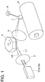
- Fig. 1 is a perspective view showing an example of the image exposure system of the present invention.
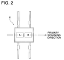
- Fig. 2 is a schematic illustration showing the details of the index sensor.
- Fig. 3 is a flow chart showing the circumstances of detection and correction of deviation.
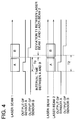
- Fig. 4 is a time chart showing the characteristics of detection of deviation time.
- Fig. 5 is a time chart showing the method for measuring detection intervals.
- Fig. 6 is a time chart showing the method for measuring detection intervals.
- Fig. 7 is a block diagram showing the circuit structure for detecting and correcting deviation.
- Fig. 1 is a view showing an example of the image exposure system of a laser printer to which the present invention is applied.
- two laser beams I1 and I2 are modulated in accordance with image data. Then, the two laser beams I1 and I2 conduct scanning in parallel with the primary scanning direction, so that two lines can be simultaneously recorded.
- the light source unit 1 includes two semiconductor lasers 1a, 1b which are in alignment. Two beams of divergent light emitted from the light source unit 1 are made to be two parallel beams L1 and L2 by the action of the condenser lens 2.
- the two laser beams L1, L2 irradiate the polygonal mirror 3. After the two laser beams L1, L2 have been reflected on the polygonal mirror 3, they pass through the f ⁇ lens 4 and scan the surface of the photoreceptor drum (recording medium) 5.
- the photoreceptor drum 5 is rotated synchronously with the primary scanning conducted by the laser beams L1 and L2. Due to the rotation of the photoreceptor drum 5, the laser beams L1 and L2 are relatively moved in the subsidiary scanning direction with respect to the photoreceptor drum 5, so that two-dimensional image recording can be performed.
- an electrostatic latent image is formed on the surface of the photoreceptor drum (recording medium) 5.
- Electrically charged toner particles the polarity of which is reverse to that of the electrostatic latent image, are deposited on the electrostatic latent image so that the latent image is developed.
- the developed toner image is transferred onto a recording sheet in such a manner that the recording sheet is put on the toner image and an electrical charge of the reverse polarity is given to the recording sheet by a corona charger disposed on the reverse side of the recording sheet.
- Starting points of scanning operations conducted by the laser beams L1 and L2 reflected on the polygonal mirror 3, are detected by the index sensor (beam detecting means) 6 disposed at a fore end side of the scanning region.
- the reflecting mirror 7 guide the laser beams L1 and L2 to the index sensor 6 when the laser beams L1 and L2 are irradiated on the end of the scanning line.
- the index sensor 6 includes two light receiving sections A and B.
- Each of the light receiving sections A and B is a sensor to output a detection signal of the laser beam.
- the light receiving sections A and B are disposed in the primary scanning directions of the laser beams L1 and L2, so that the two laser beams L1 and L2 are simultaneously incident upon the light receiving sections A and B.
- the two light receiving sections A and B of the index sensor 6 are respectively referred to as sensors A and B, that is, the following explanation will be given under the condition that the index sensor 6 includes the two beam detecting means corresponding to the number of beams.
- the laser printer of the present invention has a function of correcting the deviation of laser beams of the primary scanning direction in such a manner that the deviation in the primary scanning direction is detected and the writing positions of the laser beams L1 and L2 are controlled in accordance with the detected deviation.
- T ⁇ is defined as a period of time which has passed from when the laser L1 is detected by the sensor A on this side of the scanning direction (that is, a rise of the detection signal of the sensor A), to when the laser beam L1 is detected by the sensor B on the far side of the scanning direction (that is, a rise of the detection signal of the sensor B).
- the period of time T ⁇ corresponds to an interval between the sensors A and B under the condition of a predetermined scanning speed.
- the same interval time can be measured.
- the two semiconductor lasers 1a, 1b are controlled on the fore end side of primary scanning so that only the laser beam L1 is incident upon the sensor A and only the laser beam L2 is incident upon the sensor B (S3).
- the function of this S3 corresponds to the different beam detection control means of this example. Even in the normal image formation, the laser beams are selectively incident upon the sensors A and B as described above.
- the operation is carried out as follows: At the start of scanning, first, only the laser beam L1 is turned on, and scanning is conducted by the laser beam L1. When the laser beam L1 is detected by the sensor A, it is immediately turned off. Instead of the laser beam L1, the laser beam L2 is turned on and scanning is conducted by the laser beam L2. Then, the laser beam L2 is detected by the sensor B. After the laser beam L2 has been detected by the sensor B, both laser beams L1 and L2 are maintained in a condition in which they are ready for being turned on. In this way. Both laser beams L1 and L2 are prepared for image recording (shown in Fig. 4).
- the laser beam L1 is immediately turned off when the laser beam L1 is detected by the sensor A and the laser beam L2 is turned on instead of the laser beam L1
- a detection signal of the laser beam L2 is outputted from the sensor A when a scanning point of the laser beam L2 is set on the sensor A. Therefore, after the laser beam L1 has been detected by the sensor A, the output of the sensor A is preferably stopped, that is, the output of the sensor A is preferably subjected to masking.
- the sensor A detects the laser beam L1
- the sensor B detects the laser beam L2
- the detection interval T2 between the sensors A and B is measured (S4).
- the function of this S4 corresponds to the different beam detection interval detecting means of this example.
- the deviation T1 When the deviation T1 is a positive value, it represents a condition in which scanning is performed while the laser beam L1 is taking the lead. On the contrary, when the deviation T1 is a negative value, it represents a condition in which scanning is performed while the laser beam L2 is taking the lead.
- dl0 is a reference clock clk (reference printing clock), and 15 types of delay clocks (printing clocks) dl1 to dl15 obtained when the reference clock clk is successively delayed by 1/16 period are generated by a digital delay line.
- Fig. 5 only clocks dl0, dl1, dl2, dl10, and dl12 are shown, and other delay clocks are omitted in the drawing.
- an output time difference between the detection signals of the sensors A and B can be found in the following manner: A value obtained when 1 is subtracted from the counted number of the rises of the clock dl10 (the counted number includes the rise of clock dl10 synchronizing with the detection signal of the sensor A), is multiplied by the clock period. The obtained time is added by the phase difference (2/16 period) between the clocks dl10 and dl12. The value obtained through this addition is the output time difference between the detection signals of the sensors A and B.
- an output time difference between the detection signals of the sensors A and B can be found in the following manner: A value obtained when 1 is subtracted from the counted number of the rises of the clock dl10 (the counted number includes the rise of clock dl10 synchronizing with the detection signal of the sensor A), is multiplied by the clock period. The obtained time is added by the phase difference (4/16 period) between the clocks dl10 and dl14. The value obtained through this addition is the output time difference between the detection signals of the sensors A and B.
- the detection interval of the sensors A and B is measured in the form of the counted value of the printing clock and the phase difference of the printing clock while the minimum unit is 1/16 of the printing clock period.
- a synchronizing relation is provided as illustrated in Fig. 5.
- the counted number of the clock is 11
- the laser beams L1 and L2 are selectively incident upon the sensors a and b
- a synchronizing relation is provided as illustrated in Fig. 6, and it is assumed that the counted number of the clock is 13.
- the time measured in Fig. 5 is (10 + 2/16) ⁇ (period)
- the time measured in Fig. 6 is (12 + 4/16) ⁇ (period). Accordingly, when the count value and phase difference of the clock are respectively compared, the deviation time T1 can be found as 2 counts of the count value of the clock (2 periods of the printing clock) and also as 2/16 period of the phase difference of the clock (2 steps of delay).
- the phase difference corresponding to the deviation in a period of one clock can be expressed by the number of delay clock (the number of steps of delay).
- the number of delay clock is designated as 0, and in the case where there is a deviation of 2/16 period, the number of delay clock is designated as 2.
- the deviation time T1 of the two laser beams L1, L2 in the primary scanning direction is found by the deviation time expressed as an integral multiple of the printing clock period, and also by the phase difference (0/16 to 15/16 ⁇ period) which is a deviation in one period of the printing clock. Then, in accordance with the detection of the deviation time, the phase of the printing clock for image formation conducted by laser beams L1, L2, and the time to start the image formation are controlled. Due to the foregoing, image formation can be accurately conducted even when the beam of the primary scanning direction is deviated. In this connection, the phase of the printing clock and the time to start image formation are controlled in a section shown by S6 in Fig. 3. The function of this S6 corresponds to the deviation correction means.
- Printing clock DCLK1 corresponding to the laser beam L1 and printing clock DCLK2 corresponding to the laser beam L2 are selectively outputted from the printing clocks dl0 to dl15 so that the phases of the printing clocks can have a difference corresponding to the aforementioned deviation.
- the beam L1 is selectively incident upon the sensor A, and the detection signal of the sensor A is outputted as an index signal "index".
- a delay clock synchronizing with the index signal "index” is selected as the printing clock DCLK1 for the laser beam L1.
- a printing clock having a phase difference corresponding to the deviation with respect to the printing clock for the laser beam L1, is made to be the printing clock DCLK2 for the laser beam L2.
- the printing clock DCLK2 for the laser beam L2 may output the delay clock dl12.
- the deviation found as the count value of the printing clock is given to the HV generating section.
- an effective image region (the time for starting image formation) controlled in accordance with the count of the printing clock is controlled for for each of the laser beams L1 and L2 in accordance with the deviation of the primary scanning direction. Due to the foregoing, the beam deviation expressed by an internal multiple of the printing clock period can be corrected.
- a writing position of the laser beam L1 taking the lead is determined to be a point of time at which the count number of the printing clock DCLK1 from the index signal "index" becomes N
- a writing position of the laser beam L2 which conducts scanning behind the laser beam L1 is determined to be a point of time at which the count number of the printing clock DCLK2 from the index signal "index” becomes a count value corresponding to N + (deviation). Due to the foregoing, the deviation of an integral multiple of the period of the printing clock DCLK can be compensated.
- the deviation in one period of the printing clock DCLK which can not be controlled to the writing position by counting the printing clock DCLK, is corrected by the phase difference between the printing clocks DCLK1 and DCLK2 as described above.
- the deviation of the primary scanning direction found as the count number and phase difference of the printing clock can be corrected, and image recording can be accurately conducted by the laser beams L1 and L2.
- the outputs fsa, fsb of the sensors A, B are respectively outputted to the phase detector (1) 11 and the phase detector (2) 12.
- the reference clock CLK is inputted into the digital delay line 13.
- the digital delay line 13 outputs the delay clocks dl0 to dl15.
- the phase detectors (1), (2) 11, 12 respectively detect the delay clocks dl0 to dl15 synchronizing with the rise of the detection signals of the sensors A, B (shown in Fig. 5 or Fig. 6).
- Results pd1, pd2 of the detection are outputted to the phase difference calculating section 14.
- a phase difference (unit:1/16 period) between the delay clock synchronizing with the sensor A and the delay clock synchronizing with the sensor B is found, that is, the fractions of detection intervals of the sensors A, B in the clock period are found, and the results are latched in the latch circuit 18 in accordance with the one shot pulse generated in the one shot circuit 31.
- the detection result pdl of the phase detector (1) 11 is also outputted to the selector (1) 15, and the selector (1) 15 selectively outputs the delay clock sclk synchronizing with the detection signal of the sensor A.
- the clock sclk is given to the counter 16.
- the rising edge time of the output fsa, fsb of the sensors A, B is measured when the clock sclk is counted.
- a section to be counted by the counter 16 is controlled by the flip-flop 17 into which the outputs fsa, fsb of the sensors A, B are inputted.
- the count value cnt outputted from the counter 16 is latched to the latch circuit 18 by the action of the one shot pulse generated from the detection signal of the sensor B.
- the detection intervals of the sensors A, B are found and latched as the count value and phase difference of the clock.
- the same laser beam is incident upon the sensors A and B, and the detection interval T ⁇ of the sensors A, B is measured, and then different laser beams are incident upon the sensors A and B, and the detection interval T2 of the sensors A, B is measured. The results of measurement are latched.
- the count value and phase difference are compared as described above.
- the deviation time T1 of the laser beams L1, L2 in the primary scanning direction is calculated by the clock count value and the clock phase difference, and the result of the calculation is latched.
- the deviation time calculating section 19 when the scanning order of the two laser beams L1, L2 is discriminated from the result of calculation of the deviation time, it is determined whether the detection signal of the sensor A is made to be the index signal "index”, or the detection signal of the sensor B is made to be the index signal "index”. The result of determination is latched.
- the data of the deviation time T1 and the result of selection of the index signal "index" are latched in accordance with the trigger signal ZH generated when the time T ⁇ is measured while only one of the laser beams is turned on in the case where the power source is turned on or immediately before the image formation is started.
- the deviation found as the count value of the clock is outputted to a counter (not shown) generating the HV signal (horizontal and vertical synchronization signal) for controlling the time to start image formation.
- the deviation shown by the count value of the clock is corrected by the control of an effective image region in accordance with the count of the printing clock in which the common index signal "index" is used as reference.
- the deviation expressed by the phase difference of the printing clock is outputted into the phase difference calculation means 20.
- the selector (2) 21 into which the detection results pdl, pd2 of the phase detectors (1), (2) 11, 12 are inputted one of the detection results pd1, pd2 is outputted into the phase difference calculating section 20 in accordance with the result of selection of the index signal "index" described before.
- phase difference calculating section 20 a delay clock having the phase difference corresponding to the deviation is calculated with respect to the delay clock inputted from the selector (2) 21, then the result of the calculation is outputted into the selector (4) 22.
- the phase difference information according to the deviation correction is inputted, and also the delay clocks dl0 to dl15 is inputted from the digital delay line 13. Further, a detection signal of selected sensor A or B is inputted into the selector (4) 22 from the selector (3) 23. From the selector (4) 22, the printing clocks DCLK1, DCLK2 corresponding to the laser beams L1, L2 are outputted together with the index signal "index".
- the laser beam L1 takes the lead.
- Two laser beams L1, L2 are selectively incident upon the sensors A, B.
- the laser beam L1 is incident upon the sensor A, and the deviation of the beams L1, L2 of the primary scanning direction is an amount corresponding to 2 counts of the printing clock, and also the deviation is an amount corresponding to 2 steps (2/16 period) of the phase difference.
- a detection signal of the sensor A is outputted as the index signal "index”.
- a delay clock synchronizing with the index signal "index” is outputted as the printing clock DCLK1 corresponding to the laser beam L1.
- a delay clock having the phase difference of 2/16 period with respect to the printing clock DCLK1 is outputted as the printing clock DCLK2 for the laser beam L2.
- the printing clocks DCLK1, DCLK2 the phases of which are different, are outputted corresponding to the laser beams L1, L2, the deviation of the printing clock in one period can be corrected as the phase difference of the printing clock.
- the synchronizing circuit shown in Fig. 3 includes the phase detectors (1), (2) 11, 12, digital delay line 13, phase difference calculating section 20, selector (2) 21, selector (4) 22, and selector (3) 23.
- the deviation of an integral multiple of the printing clock period is reflected on the control (HV generating section) by which the writing positions (the time of the start of image formation) of the laser beams L1, L2 are respectively set in accordance with the count of the printing clock.
- the correction in which the image formation start time of the laser beams L1, L2 is deviated by integral multiples of the clock period can be realized by the construction in which the count number of the printing clock is made to differ with reference to the common index signal "index".
- the following construction may be employed: With respect to the index signal "index" for the beam L1, an index signal “index” for the beam L2 is generated in which the phase is delayed by the clock period corresponding to the detected deviation. With reference to the index signal "index" of each beam, the image formation start time is controlled in accordance with the same count number.
- a detection signal of the sensor B is used as the index signal "index”.
- the image formation start time of the beam L1 which conducts scanning after the detection of the beam L2 by the sensor B, and the phase of the printing clock are delayed for correction in the same manner as the above example.
- relations between the sensors A, B and the beams L1, L2 may be changed so that the laser beam L2 is incident upon the sensor A, and the laser beam L2 is incident upon the sensor B.
- the detection signal of the sensor A may be used as the index signal "index" at all times.
- the operation is conducted in the following manner: Three light receiving sections A, B, C aligned in the scanning direction are provided as the index sensor 6. First, only one of the laser beams is turned on so as to conduct scanning, and the interval time T ⁇ 1 between A and B, and the interval time T ⁇ 2 between B and C are detected.
- the laser beam L1 is selectively incident upon the sensor A
- the laser beam L2 is selectively incident upon the sensor B
- the laser beam L3 is selectively incident upon the sensor C.
- detection signals are provided by the sensors A, B, C.
- detection signal interval T2-1 between A and B, and detection signal interval T2-2 between B and C are measured.
- the delay time T1L2 of the laser beam L2 with respect to the laser beam L1 is calculated, and as the deviation between T2-2 and T ⁇ 2, the delay time T1L3 of the laser beam L3 with respect to the laser beam L2 is calculated.
- the measurement is conducted with respect to the count of the printing clock and the phase difference.
- the deviation expressed by the count number of the printing clock is reflected on the image formation start time controlled in accordance with the count of the printing clock.
- the deviation expressed by the phase difference of the printing clock is compensated by the phase difference of the printing clock corresponding to each beam.
- the phase of the printing clock and the image formation start time for image formation conducted by each light beam are controlled in accordance with the deviation of the light beam of the primary scanning direction. Therefore, even if a positional relation between the plurality of light beams of the primary scanning direction is not constant, an accurate image formation can be simply and stably carried out.
Landscapes
- Engineering & Computer Science (AREA)
- Multimedia (AREA)
- Signal Processing (AREA)
- Physics & Mathematics (AREA)
- Optics & Photonics (AREA)
- General Engineering & Computer Science (AREA)
- General Physics & Mathematics (AREA)
- Theoretical Computer Science (AREA)
- Laser Beam Printer (AREA)
- Mechanical Optical Scanning Systems (AREA)
- Dot-Matrix Printers And Others (AREA)
- Facsimile Scanning Arrangements (AREA)
Applications Claiming Priority (2)
| Application Number | Priority Date | Filing Date | Title |
|---|---|---|---|
| JP88829/93 | 1993-04-15 | ||
| JP08882993A JP3191231B2 (ja) | 1993-04-15 | 1993-04-15 | 画像形成装置の主走査方向ビームずれ補正装置 |
Publications (1)
| Publication Number | Publication Date |
|---|---|
| EP0620671A1 true EP0620671A1 (de) | 1994-10-19 |
Family
ID=13953838
Family Applications (1)
| Application Number | Title | Priority Date | Filing Date |
|---|---|---|---|
| EP94302111A Withdrawn EP0620671A1 (de) | 1993-04-15 | 1994-03-23 | Mehrstrahlbilderzeugungsgerät |
Country Status (3)
| Country | Link |
|---|---|
| US (1) | US5426528A (de) |
| EP (1) | EP0620671A1 (de) |
| JP (1) | JP3191231B2 (de) |
Cited By (2)
| Publication number | Priority date | Publication date | Assignee | Title |
|---|---|---|---|---|
| EP0810768A1 (de) * | 1996-05-29 | 1997-12-03 | Konica Corporation | Bilderzeugungsgerät |
| EP1445937A3 (de) * | 2003-02-05 | 2006-12-27 | Samsung Electronics Co., Ltd. | Laserdruckgerät |
Families Citing this family (13)
| Publication number | Priority date | Publication date | Assignee | Title |
|---|---|---|---|---|
| US5617132A (en) * | 1994-12-01 | 1997-04-01 | Xerox Corporation | Method and apparatus for adjusting the pixel placement in a raster output scanner |
| JPH09307710A (ja) * | 1996-05-10 | 1997-11-28 | Brother Ind Ltd | 画像読取記録装置 |
| JPH10142546A (ja) * | 1996-11-06 | 1998-05-29 | Fuji Xerox Co Ltd | 焦点調節方法及びそれに使用する光ビーム光学装置及びそれを用いた画像形成装置 |
| JPH11227252A (ja) * | 1998-02-19 | 1999-08-24 | Fuji Xerox Co Ltd | 画像形成装置 |
| US6055010A (en) * | 1998-06-26 | 2000-04-25 | Eastman Kodak Company | Method and apparatus for controlling operation of a printer |
| US6185026B1 (en) * | 1998-08-06 | 2001-02-06 | Ricoh Company, Ltd. | Multi-beam scanning apparatus |
| US5966231A (en) * | 1998-08-07 | 1999-10-12 | Lexmark International, Inc. | Method and apparatus for aligning multiple laser beams |
| US6493019B1 (en) * | 1999-01-29 | 2002-12-10 | Canon Kabushiki Kaisha | Image forming apparatus |
| JP2002267963A (ja) | 2001-03-07 | 2002-09-18 | Ricoh Co Ltd | 画像形成装置 |
| JP2003131157A (ja) | 2001-10-26 | 2003-05-08 | Ricoh Co Ltd | 画像形成装置 |
| JP4566723B2 (ja) * | 2004-12-08 | 2010-10-20 | キヤノン株式会社 | レーザスキャナ及びそれを適用する画像形成装置 |
| US10955547B2 (en) | 2018-05-24 | 2021-03-23 | The Boeing Company | Combined radar and communications system using common signal waveform |
| CN111367073B (zh) * | 2020-04-29 | 2022-03-29 | 中国科学院光电技术研究所 | 一种基于位置修正模式的单检测复合轴控制系统设计方法 |
Citations (3)
| Publication number | Priority date | Publication date | Assignee | Title |
|---|---|---|---|---|
| US4933549A (en) * | 1987-12-11 | 1990-06-12 | Ricoh Company, Ltd. | Light beam scanning apparatus |
| US4950889A (en) * | 1989-08-01 | 1990-08-21 | International Business Machines Corporation | Chromatic and misalignment compensation in a multiple beam laser scanning system |
| EP0412036A2 (de) * | 1989-08-01 | 1991-02-06 | International Business Machines Corporation | Bildpunktpositionierungskorrektur in dem Abtastbereich eines Mehrstrahl-Laserabtastsystemes |
Family Cites Families (2)
| Publication number | Priority date | Publication date | Assignee | Title |
|---|---|---|---|---|
| EP0342936B1 (de) * | 1988-05-19 | 1994-03-09 | Canon Kabushiki Kaisha | Optische Abtastvorrichtung |
| JPH02188713A (ja) * | 1989-01-17 | 1990-07-24 | Canon Inc | 画像形成装置 |
-
1993
- 1993-04-15 JP JP08882993A patent/JP3191231B2/ja not_active Expired - Fee Related
-
1994
- 1994-03-16 US US08/213,956 patent/US5426528A/en not_active Expired - Fee Related
- 1994-03-23 EP EP94302111A patent/EP0620671A1/de not_active Withdrawn
Patent Citations (3)
| Publication number | Priority date | Publication date | Assignee | Title |
|---|---|---|---|---|
| US4933549A (en) * | 1987-12-11 | 1990-06-12 | Ricoh Company, Ltd. | Light beam scanning apparatus |
| US4950889A (en) * | 1989-08-01 | 1990-08-21 | International Business Machines Corporation | Chromatic and misalignment compensation in a multiple beam laser scanning system |
| EP0412036A2 (de) * | 1989-08-01 | 1991-02-06 | International Business Machines Corporation | Bildpunktpositionierungskorrektur in dem Abtastbereich eines Mehrstrahl-Laserabtastsystemes |
Cited By (4)
| Publication number | Priority date | Publication date | Assignee | Title |
|---|---|---|---|---|
| EP0810768A1 (de) * | 1996-05-29 | 1997-12-03 | Konica Corporation | Bilderzeugungsgerät |
| US6198495B1 (en) | 1996-05-29 | 2001-03-06 | Konica Corporation | Color image forming apparatus having means for correcting deviations between scanning light beams accurately and in real time |
| EP1445937A3 (de) * | 2003-02-05 | 2006-12-27 | Samsung Electronics Co., Ltd. | Laserdruckgerät |
| US7209158B2 (en) | 2003-02-05 | 2007-04-24 | Samsung Electronics Co., Ltd. | Scanning line alignment compensation apparatus and method for a laser printer |
Also Published As
| Publication number | Publication date |
|---|---|
| JP3191231B2 (ja) | 2001-07-23 |
| US5426528A (en) | 1995-06-20 |
| JPH06300980A (ja) | 1994-10-28 |
Similar Documents
| Publication | Publication Date | Title |
|---|---|---|
| US5426528A (en) | Correction device of light beam deviation of primary scanning direction thereof in image forming apparatus | |
| KR100555000B1 (ko) | 화상 형성 장치 | |
| EP0632302B1 (de) | Abbildende Vorrichtung | |
| US5576852A (en) | Synchronization signal generating unit of an image forming apparatus | |
| US6469730B2 (en) | Light beam scanning apparatus and image forming apparatus | |
| EP0412036B1 (de) | Bildpunktpositionierungskorrektur in dem Abtastbereich eines Mehrstrahl-Laserabtastsystemes | |
| EP0668522B1 (de) | Lichtbündelablenkungsdetektionsgerät für Abbildungsgeräte | |
| US6198495B1 (en) | Color image forming apparatus having means for correcting deviations between scanning light beams accurately and in real time | |
| US7724275B2 (en) | Image forming apparatus and control method thereof | |
| EP0617541B1 (de) | Bilderzeugungsgerät zum Erzeugen einer Abbildung mit Hilfe von mehreren Laserstrahlabtastern | |
| US5349374A (en) | Color image forming device to prevent color shifting | |
| JPH0423265B2 (de) | ||
| US4635129A (en) | Image scanning apparatus | |
| US6195108B1 (en) | Image formation method for forming electrostatic latent image on photosensitive belt with laser beam and image formation apparatus of the same | |
| US20070286624A1 (en) | Optical scanning apparatus | |
| EP0998112B1 (de) | Optisches Abtastsystem für Drucker und Verfahren zum Einstellen des Bildabtaststartpunktes | |
| JP3471060B2 (ja) | 画像形成装置の同期信号発生装置 | |
| JP4103386B2 (ja) | マルチビーム光走査方法ならびに画像形成方法 | |
| US6791722B1 (en) | Light beam scanning apparatus and image forming apparatus | |
| JP3259198B2 (ja) | 画像形成装置の同期信号発生装置 | |
| JP2006251019A (ja) | 画像形成装置 | |
| JP6758906B2 (ja) | 画像形成装置 | |
| JP2536838B2 (ja) | 水平同期信号出力装置 | |
| JPH07270694A (ja) | 画像形成装置の同期信号発生装置 | |
| JPH10307267A (ja) | 光走査装置及びこれに用いる水平同期制御回路 |
Legal Events
| Date | Code | Title | Description |
|---|---|---|---|
| PUAI | Public reference made under article 153(3) epc to a published international application that has entered the european phase |
Free format text: ORIGINAL CODE: 0009012 |
|
| AK | Designated contracting states |
Kind code of ref document: A1 Designated state(s): DE FR GB IT NL |
|
| 17P | Request for examination filed |
Effective date: 19950215 |
|
| 17Q | First examination report despatched |
Effective date: 19961017 |
|
| STAA | Information on the status of an ep patent application or granted ep patent |
Free format text: STATUS: THE APPLICATION IS DEEMED TO BE WITHDRAWN |
|
| 18D | Application deemed to be withdrawn |
Effective date: 19970428 |