EP0620935B1 - Gestion d'appel dans un reseau fonctionnant en collaboration - Google Patents
Gestion d'appel dans un reseau fonctionnant en collaboration Download PDFInfo
- Publication number
- EP0620935B1 EP0620935B1 EP93924737A EP93924737A EP0620935B1 EP 0620935 B1 EP0620935 B1 EP 0620935B1 EP 93924737 A EP93924737 A EP 93924737A EP 93924737 A EP93924737 A EP 93924737A EP 0620935 B1 EP0620935 B1 EP 0620935B1
- Authority
- EP
- European Patent Office
- Prior art keywords
- application
- call
- call manager
- data
- node
- Prior art date
- Legal status (The legal status is an assumption and is not a legal conclusion. Google has not performed a legal analysis and makes no representation as to the accuracy of the status listed.)
- Expired - Lifetime
Links
Images


Classifications
-
- G—PHYSICS
- G06—COMPUTING OR CALCULATING; COUNTING
- G06F—ELECTRIC DIGITAL DATA PROCESSING
- G06F9/00—Arrangements for program control, e.g. control units
- G06F9/06—Arrangements for program control, e.g. control units using stored programs, i.e. using an internal store of processing equipment to receive or retain programs
- G06F9/46—Multiprogramming arrangements
- G06F9/54—Interprogram communication
- G06F9/542—Event management; Broadcasting; Multicasting; Notifications
-
- G—PHYSICS
- G06—COMPUTING OR CALCULATING; COUNTING
- G06F—ELECTRIC DIGITAL DATA PROCESSING
- G06F9/00—Arrangements for program control, e.g. control units
- G06F9/06—Arrangements for program control, e.g. control units using stored programs, i.e. using an internal store of processing equipment to receive or retain programs
- G06F9/46—Multiprogramming arrangements
- G06F9/54—Interprogram communication
- G06F9/544—Buffers; Shared memory; Pipes
-
- G—PHYSICS
- G06—COMPUTING OR CALCULATING; COUNTING
- G06F—ELECTRIC DIGITAL DATA PROCESSING
- G06F2209/00—Indexing scheme relating to G06F9/00
- G06F2209/54—Indexing scheme relating to G06F9/54
- G06F2209/544—Remote
Definitions
- This invention relates to call management in a collaborative working network and more specifically to a programmable workstation and a method for use in such a collaborative working environment.
- Personal computers are now widespread throughout the business community and many are able to intercommunicate, either through fixed connections e.g. local area networks, or through dynamically established links e.g. ISDN or async lines over the public switched telephone network.
- these connected personal computers can be used to enhance collaborative working between remote individuals; a typical example being the use of desk top conferencing software.
- Successful collaborative work generally requires more than a simple data link between the participants; voice capabilities are normally essential and video links are frequently required.
- remote collaborative working can often be regarded as an extension to the traditional telephone call - it being enhanced with the data and programs available at the desktop via the personal computer - and, on occasions, enriched with video services.
- a broad spectrum of collaborative applications can be envisaged, ranging from utilities taking advantage of the data and applications on a workstation, e.g. sharing of screen windows and files, through to new collaborative applications designed to meet the needs of specific classes of remote user e.g. just-in-time education, remote presentations, executive broadcasts or help desk.
- the common requirements behind these examples are:
- the behaviour of a desk top conferencing system is usually determined by the suppliers of the system software.
- the conventional view of real-time desk top conferencing makes a distinction between the system functions, such as setting up and tearing down calls, and application functions, such as sending and receiving data.
- applications such as a shared electronic chalkboard
- the barring of incoming calls is normally regarded as a system function which can be toggled on and off by the user and perhaps, via an API call, by an application program.
- the invention provides a programmable workstation for collaborative working in a network of workstations forming the nodes of the network, the network being connected by physical links for the transmission of data between nodes ;
- the invention further provides a method of collaborative working in a network of programmable workstations forming the nodes of a network connected by physical links for the transmission of data between nodes, the method comprising in response to a predetermined application programming interface call from a call manager program running on the workstation, establishing the call manager program as the new call manager at the node to handle incoming events which are not specific to any application program instance at the node.
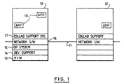
- FIG 1 In Figure 1 are shown two programmable workstations 10 and 12 connected by link 11 in a network, such as a LAN or WAN.
- the principal components of the workstations are conventionally described as layers, starting with the hardware 13.
- the hardware which is not illustrated in detail, consists of a processor unit with main memory, secondary storage such as a disk file, a display unit and input/output devices such as keyboard and mouse.
- Device support software 14 enables the hardware devices to function within a known operating system 15, such as IBM's Operating System/2 (OS/2).
- OS/2 IBM's Operating System/2
- networking software 16 for supporting connection to the network 11 and communication over the network between workstations.
- Typical networking software 16 could be the Netbios program product from IBM. Up to this point all that has been described is a conventional networking workstation capable of executing application programs 18.
- each workstation also includes collaborative application support system software 17 which facilitates the development of application programs for creating a distributed collaborative working environment.
- collaborative application support system software 17 facilitates the development of application programs for creating a distributed collaborative working environment.
- end-users of the workstation may communicate with users of other workstations in the network over multi-media channels and may work collaboratively on shared data and tasks.
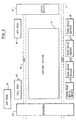
- support system 17 in relation to other software components of the workstation with which it interfaces directly is shown in Figure 2. Further details of the internal structure of the support system are shown in Figure 10. Broadly speaking, the main functional components of system 17 lie between two interfaces 20 and 21, illustrated by dashed lines.
- An application programing interface 20 allows applications 18 to request support services.
- a device driver interface 21 allows the system to support an extensible range of software and hardware communications subsystems through device drivers such as token ring driver 25, ISDN driver 26, RS232 driver 27 and other device drivers 28.
- Link support modules 228, 229 interface with the device drivers. These are replaceable, ( Figure 10 shows only a possible selection) depending on the hardware options available at the workstation, and serve to isolate the support system from needing to know precisely which hardware is present.
- an implicit resources interface (not illustrated) details of the communications network, such as node addresses and directory data may be requested by both the support system, the applications and the device drivers from resource files 29.
- the API 20 allows applications 18 to initiate peer applications and share resources, on a variety of hardware and software platforms, located on nodes across a diverse and complex communications networks. It allows them to define multiple dedicated logical data channels between shared applications, suitable to a broad range of multi-media traffic, independently of the structure of the underlying physical network. It allows them to serialise, synchronise, merge or copy the data streaming between shared applications. It also allows them to support a range of attached devices and to allow the interception and redirection of the device data.
- the support system includes other components to assist application development such as an extensible set of logical devices 30, interfacing to external applications and devices. Also provided is a set of end-user utilities, written to the API (not illustrated), which can also invoked from applications through a command interface.
- the programming model presented by the API consists of a communicating set of nodes.
- a node is the addressable entity representing a user, and comprises an instance of the support system software, and a set of resources such as application programs, data etc.
- a node is typically a dedicated programmable workstation 10, capable of communicating with its peers; in a multi-user system a node is associated with each user.
- Nodes are either supported nodes or non-supported nodes; a supported node is one where the support system software 17 is being executed. A collection of inter-communicating supported nodes is called a supported network.
- Nodes are identified by name; ideally all node names should be unique but duplicates can be tolerated as long as their associated nodes are never required to inter-communicate.
- the choice of node naming scheme is not directly relevant to the present invention, although a hierarchical system such as that defined by the Internet protocol has many benefits. It is fundamental to the architecture that a node can dynamically join or leave the network.
- Nodes can contain logical devices 30.
- a logical device is a software extension to the support system that allows an application to manipulate or manage software or equipment, in a manner consistent with other entities in the architecture. There is an extensive range of possible logical devices including: presentation windows, printers, disk drives, modems, and application programs.
- Applications can be executed at a node, subject to the constraints imposed there by the operating and windowing system.
- Applications are either aware or unaware; an aware application uses the services of the API; an unaware application does not. Both aware and unaware applications will generally be executing simultaneously at a node.
- call manager 32 When the support system is fully active at a node, one particular aware application must be running at that node. This application plays a unique role at that node and is known as call manager 32. Many call managers may be available for execution at a particular node but only one can execute at a time. The distinguishing feature of a call manager is that it responds to certain events generated by the support system; for example, it resolves any requests that are not directed specifically at an instance of an application, and optionally it may also handle resource management for the node. Call manager responsibility can be transferred from one call manager to another; also the role can be combined with user application function if that is appropriate.
- the support software 17 may request that the resources of one node are made available for communication between two other nodes; this is termed passive operation and permission is controlled by the call manager at the passive node.
- passive operation As an example, consider two nodes A and B on a LAN, with a third node C connected to B by an asynchronous communications link. If applications at A and C wish to communicate, the traffic will need to be routed via B. The consent of the call manager at B is required for this use of its node.
- Aware applications can share data and resources with other aware applications at the same or different nodes.
- a collection of applications sharing is called a sharing set.
- An aware application initiates a share request, naming an application sharing set, a target application and a destination node. This request is first passed by the support software to the call manager at the sending node, which will typically transfer it to the call manager at the destination node. Usually this second call manager will launch the requested application and the source application will be informed.
- the participation of the call managers in this process allows both local control of the sharing process and other actions to be initiated if necessary.
- the call managers play a vital role in resolving the names used by applications to idnetify other nodes and applications.
- the sharing mechanism can be cascaded; for example, if two applications are already sharing, one of them can initiate a share with a third application naming the same sharing set, with the result that all three applications are then sharing with each other.
- Applications may also make local share requests on behalf of other applications thereby allowing membership control of the sharing set to be delegated.
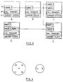
- Figure 3 shows a number of applications A-E sharing. This results in two sharing sets, irrespective of the order in which the shares were requested, as illustrated in Figure 4.
- channels such as 43 and 44 are logically dedicated and uni-directional pipes, with application specified transmission characteristics.
- a channel is always defined by the sending application and it goes from a sending application to a receiving application.
- the ends of channels are known as ports; thus all channels have one sending port and one receiving port.
- a sending port such as 45 sends data packets down the channel; a receiving port such as 46 receives data packets from the channel in the order in which they were sent.
- An application may establish multiple channels to another application as a convenient way to separate data traffic of different types.
- the system network manager 31, Fig. 2 may map some or all of the logical channels on to a single physical link such as link 11, Fig. 1 but this will be invisible to the application.
- Channels have a number of quality of service characteristics, initially negotiated with the support system 17 during the creation process, which allow data transmission characteristics to be tailored to the requirements of the expected traffic. These characteristics include encryption. compression hints. Encryption allows the data to be encrypted during transmission along the channel; compression hints allow the system the option of compressing the data over narrow bandwidth links.
- Quality of service parameters are defined according to signal type, which distinguishes analog from digital data. They need not be specified explicitly, but can be notified to the support system in terms of data classes. This mechanism allows video channels, voice channels and other data channels to be sensibly established. Channel characteristics can be re-negotiated after channel creation. The data transmission characteristics are implemented in the real network by means of the data transformation manager 32, Fig. 2 in response to the characteristics specified in the channel creation calls over the API.
- Standard channels are the default case; the other types are used in conjunction with collections of channels, known as channel sets.
- channel sets are the collections of channels, known as channel sets.
- Through a merged channel set data packets are combined from multiple channels and delivered to each receiving application through a single port. There is no guarantee that each application receives all the data packets in the same sequence, only that each application receives all the packets.
- Through a serialising channel set data packets are combined from different channels, serialised, and delivered to each application such that each receiving port receives the same sequence of data.
- a synchronising channel set data is synchronised, so that the data packets on separate channels are tied together in time (for example voice with video), but delivered through the individual ports belonging to the channels.
- FIG. 6 An example of data serialisation is illustrated by a shared drawing board application illustrated in Figure 6.
- Two identical applications, A and B (50 and 52), allow their users to draw on a single shared surface.
- all the drawing orders at A must be sent to B via ports 53 and 54, and vice versa via ports 55 and 56, in such a way that the sequence processed at A and B is identical.
- This is accomplished by each transmitting their own data both to each other and to themselves, over two channels 57 and 58 which are members of a common serialising channel set 59.
- data synchronisation is illustrated by an application A (60), that needs to send lip-synchronised video and voice to application B (61).
- Two channels 62 and 63 are used for the transmission, each being a member of the same synchronising channel set 64.
- Channels can be explicitly created by an API call to the support system, specifying the required channel characteristics, and new channels can also be added to an existing port.
- the latter mechanism allows a port to be shared across channels belonging to different channel sets; for example data can be sent from a single port to one set of destinations belonging to a merged channel set, and to a second set of destinations belonging to a serialised channel set.
- Digital channels and analog channels cannot be members of the same channel set.
- a channel can be deleted, the channel being uniquely identified by specifying its sending and receiving ports.
- Channels can be implicitly created as a consequence of an application being, or becoming, a member of an application sharing set. For example, if unshared applications already have a merged or serialized channel, and the channel set name used is identical across these applications, then when the applications share with each other, the additional channels required will be created automatically. Applications are notified of channels implicitly created in this way.
- Ports have an assigned connect type: event, command or null.
- Event ports generate an event when data is either available or is required; command ports allow the application to drive the receipt or supply of data to the port.
- Null ports are reserved for ports that are unable to supply data to an application e.g. ports associated with analogue channels, such as the sending port of a video camera.
- Ports can be controlled through "signal_port" commands sent to their port event handler. These can be issued to the local port and can be passed to any other port in the channel. Normally, the signal commands for channel ports will be sent to the port event handler of the application either supplying or receiving data, and may be used for example to stop, start, decrease or increase the data flow. The order of signals between a source and target is maintained. Signals sent to receiving ports in a serialising channel set are serialised themselves, so that all sources receive the same sequence of commands. Other typical signals are "rewind” or “pause” to a tape drive, or “change paper size” to a printer device.
- User exits can be optionally associated with ports. This allows monitoring or manipulation of the data, after it has been supplied to a sending port, or before being presented by a receiving port. In the case of synchronised channels, synchronisation is performed from after the data leaves the sending port user exit, and up to the data being presented to the receiving port user exit.
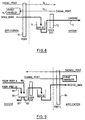
- FIG. 8 The overall structure of a standard sending command port is shown in Figure 8.
- a "send_data" command from an application data is queued in a buffer 71 of port 70.
- the application empties the buffer to send data asynchronously over a channel 73 via a user exit 72.
- Incoming "signal_port” commands are received by the port event handler 74, independently of channel 73 on line 75 and can be retransmitted outwardly on line 76.
- Receiving ports are effectively the mirror image of the corresponding sending port.
- the structure is similar, but in this case the event handler processes both the data and the port commands.
- Serialisation logically involves the collection of all events in a central point, followed by the broadcast of each event to all the destinations for that event. Diagrammatically, this is represented by Figure 9 for the case of two ports A and B on channels 80 and 81, serialising their output at 82 and 83 to port C (84) and another port (not shown) in serialising process 85.
- Serialisation can be implemented at a single central point with all data being sent there for serialisation and subsequent distribution; alternatively the serialisation process itself can be distributed.
- a receiving port can cause the sending port to stop sending data down the channel, with the option to either discard or deliver the remaining data in the channel. Suspended data transmission can be resumed subsequently.
- Ports are associated with a data class which specifies data type and data sub-type.
- the data type identifies the nature of the data, e.g. voice, video, file etc. and also distinguishes analogue from digital data.
- the data types are further subdivided according to the precise format of the data; thus examples of voice sub-types are G.711, G.721, G.722.
- the data class may be queried by an application to obtain the data format, independently of the data stream itself, without relying on other applications. Additionally, the data type may be different at the sending and receiving ports, with Lakes performing the conversions below the API.
- ports and channels can be changed after they have been initially established; for example, quality of service, data class and compression hints. This provides the flexibility for an application to modify its communications usage during execution; an example being the temporary degradation of video quality to improve file exchange performance.
- Ports can be connected together to establish extended communication links, so that an application may route its inputs through to another application for processing. When ports are connected in this way, and providing user exits have not been established, no further application involvement is required after the routing has been established. This allows the streaming of data between applications and devices. Connection is permitted between channels in different channel sets, of different types, having different quality of service characteristics, of different data class or different connect types (unless one of the ports is null), provided only that one port is sending and one port is receiving. Connected ports can also be welded, so that the connection is permanent and persists even when the local application has terminated. The channel behaves in all respects as though it had been originally created from its source directly to its destination. Any user exits which may be present are removed.
- Logical Devices 30 are supported by the support system to enable (i) easier access to system resource and devices, such as clipboard, DDE, printer and video devices, (ii) unaware applications to be used for collaborative working, for example by giving access to the window contents and file activity of an unaware application, and (iii) end to end data streaming without application involvement.
- Frequently used devices include: video capture, video playback, audio playback etc. and facilities are provided for additional devices to be defined.
- Logical devices are identified by type; the type names are local to a node. When opened, they present a port to the application: a single logical device can have multiple ports, moreover a device can simultaneously present ports to different applications at the same node.
- Opened logical devices can be controlled through commands sent to the signal port, the commands being specific to the particualr logical device. Typical commands to a device port are rewind or pause to a tape drive. The device status, for example whether data is available, can also be queried.
- Devices are exactly like channel ports, except that no user exit is present.
- Applications can connect ports on logical devices to a channel port; this enable data to flow to or from the device and across the channel. This data flow does not require further application involvement once the connection has been made. For example, data can be streamed from a camera through a camera logical device, across a channel, and displayed by a window logical device.
- the application can control the two logical devices via there signal ports; when the transmission is no longer required, the application can disconnect the ports, close the devices and remove the channel.
- Device ports cannot be welded to channel ports, since this would allow a device to exist outside the control of a local application.
- Logical devices are permitted to issue API calls to the support system, and in this regard act on behalf of the owning application (ie the application which opened the device). Devices for example can cause their owning application to share with other applications, create channels, and send or receive data.
- Potential devices include: - system clipboard - LPTx - DDE - window - shared clipboard - printer - serial emulator - file - video - codec - audio - telephone
- the system clipboard device may be opened by an application to provide a sending and a receiving port, giving access to the windowing system clipboard data at that node. Only one sending port may exist at any time, but any application at that node may open receiving ports. Through the use of channels, system clipboard data from one node, can be simply routed across to other members of an application sharing set.
- the shared clipboard is provided to ease data sharing. It is unique to a sharing set; only one sending port is allowed but multiple receiving ports are supported. Apart from these distinctions, it behaves in a similar manner to the system clipboard and provides a simple mechanism for applications to share common data.
- the window device allows a window, defined on the screen, to be associated with a sending or a receiving port (or in some circumstances both).
- the sending port can be connected to a channel port and data can be streamed to the window and displayed.
- a variety of data formats are supported.
- the DDE device can be opened to provide sending and receiving ports which are coupled to the dynamic data exchange mechanism. Through this device an aware application can control an application that supports DDE, or be itself controlled. Moreover, by establishing the appropriate channels, two remote DDE applications can be linked together.
- the printer device allows data to be sent to the system printer; only a single sending port is permitted.
- the asynchronous serial device supports one sending port and multiple receiving ports and interfaces to RS232, RS422 and other serial communications.
- video and audio devices exist including: the video display and playback devices (supporting IBM/Intel ActionMedia II Adapter/A); the video capture device (supporting IBM M-Video Capture Adapter/A); the audio capture and playback devices (supporting IBM M-Audio Capture and Playback Adapter/A); and other specialised audio/video devices (such as H320 compliant codecs).
- a number of aware applications are shipped as system utilities, and take advantage of these devices to offer general purpose end user functions, for collaborative working over a network.
- Customisation information for the support system 17 is stored in an appropriate platform-designated repository; for Windows and OS/2 these are the files called LAKES.INI and LAKESQOS.INI, formatted as a standard ASCII file, containing sections headed by an identifier, where keywords and their values are kept. Applications may also have their own additional initialisation filed.
- LAKES.INI contains standard section including information on configuration and start-up options, aware applications, devices and physical communications link; additionally application sections containing data specific to those applications may be present.
- LAKEQOS.INI contains quality of service information relating to physical links and data classes. Calls to access and update these files are provided in the API.
- resources owned by a node can be shared with other nodes.
- Such resources are considered to be global resources and access is controlled through global tokens.
- Other resources are local to application sharing set, for example a shared pointer, and access to these is managed through application tokens.
- a token owner determines the significance of a token and allocates it on request. At the discretion of the owner, queued requests may be permitted, and more than one concurrent holder of a particular token may be allowed. Token owners can optionally force holders to hand back tokens.
- Global tokens share a common name space throughout the network, but since applications are expected to know the location of a globally available resource that they require, duplicate global token names are permitted. Facilities for the broadcasting of availability information are not provided: Instead, the call manager at the node with the global resource is responsible for resource management and therefore holds any global tokens. Global tokens may be held by an application instance on an exclusive or shared basis; token ownership, however, cannot be transferred to an application. Requests for a global token may be queued, with the queue being held above the API and managed by the node call manager. Access to global tokens is not restricted to a sharing application set.
- Application token name space is restricted to the application sharing set. Tokens may be owned by any member application and ownership can be transferred. Application tokens may be held on an exclusive or shared basis and requests for tokens queued, with the queue being held above the API, and managed by the current application token owner.
- the support system is started by running a LAKES.EXE file, which reads the profile data from the file LAKES.INI.
- the named call manager is started by the support system, which then registers itself as an aware application.
- a "set_call_manager" command then establishes this particular application as the call manager for that node. After this command, the support system is fully active at that node and is able to process incoming events and requests.
- Aware applications can be initiated, either by the usual operating system procedures, such as a double click on an icon, or by a "launch" command.
- the application will register with the support system, and in the return data receive its application and node handles.
- the call manager is notified of this registration, and supplied a handle to the application.
- the launching application is returned a handle to the application; this is only valid in very restricted circumstances until the launched application has registered with the support system.
- the return data provides the launched application with its application and node handles. Both the call manager and the application that specified the launch (if different) are notified accordingly.
- Applications may revert to unaware application status by de-registering, the call manager being notified. All tokens held are released and the token owners are notified; all tokens owned become invalid. If the application is a member of an application sharing set it is removed and the other members notified of its departure. All ports created by the application are destoyed and the other applications owning ports to the affected channels are notified. All channels connected by the terminating application are welded and appropriate events raised at the end channel ports. Appropriate events are raised as necessary to the local call manager, plus the call managers of any nodes supporting a welded channel on behalf of the deregistering application. All open logical devices are closed; if any of the logical devices are connected to ports, destroyed as part of the deregistration process, then the whole connected channel is destroyed and the appropriate events raised.
- a shutdown request can be issued by an application to close down the support system at a node in an orderly manner. This raises an event in the local call manager, and if the call manager accepts the request, corresponding shutdown events are raised at the other applications. These then prepare to close down and de-register, each de-registration being notified to the call manager. After the call manager has been notified that all the applications have de-registered, it too de-registers, to complete the shutdown.
- the normal operation of the support system depends on the presence of the call manager. It is possible to replace the existing call manager with another, but the existing call manager may reject the request to do so.
- Apps may join other applications in a sharing set by issuing the "share_app" request and naming an application sharing set; the normal case being where the target application and node are both specified by name. If an application at one node wants to share, by name, with an already existing instance of an application at another node, then the procedure is as follows. App 1 at node 1 issues the "share_app" request, specifying its own applciation and node handles as the source, and the names of app 2 and node 2 as the target. After verification with the call manager at node 1, an appropriate request is sent by the support system to the call manager at node 2. Providing this call manager accepts the request, this is then passed onto app 2, which can return a confirmation, assuming that it wishes to accept the share. This scheme provides for considerable flexibility in application sharing. Each call manager is aware of the share activity at its node, whether applications are the source or target of "share_app" requests.
- a call manager has the following options on receipt of a share request: (i) handle the share itself (ii) transfer the share request (iii) reject the share (iv) launch a new application to handle the share (v) change the application and node name.
- An application is not a member of an application sharing set when launched.
- the source application issues a "share_app" request it has the option of naming the resulting sharing set: if it does not name the sharing set then the target must supply the name. After the share, both the target and the source join a new sharing set with this name. If either the source and/or the target were already members of a sharing set with this same name, then those sharing sets are merged with the newly created sharing set.
- Applications can leave a sharing set using the "unshare_app" request.
- Channels are intended to support the transfer of volume data between applications. They provide the only means of controlling the transport characteristics.
- the use of channels is restricted to applications within the same application sharing set.
- target application handle When requesting the creation of a channel, the following information is specified: target application handle, channel set type and identifier, data class, maximum buffer size, user exit, node handle, quality of service, connect type, port event handler, user information.
- An alternative approach to channel creation is to take advantage of the channels created when applications with existing merged or serialised channel set are involved in application sharing.
- Data is sent over channels by applications in packets: at the physical level the unit of data transmission is a frame. Certain data is spoilable, ie under certain conditions, if it cannot be delivered in time to meet the quality of service requirements, then it may be discarded. Some packets can be marked as spoilable, other packets as spoilers. A spoiler packet, if present, will cause the removal of those spoilable packets with which it has been associated. This technique supports for example the implementation of buffer management schemes for video, where certain pacekts are delta frame packets, and others are full frame packets. Selected sequences of delta frame packets can and must be deleted if a full frame is available.
- a single logical device can present ports to multiple applications; the logical device can then move data between the ports.
- This transport mechanism is not restricted to applications within the same sharing set and therefore overcomes a limitation placed on channels; however logical devices cannot span across nodes. Moreover any necessary quality of service support must be explicitly provided for by the particular logical device.
- the channels may be established directly, using a "create_channel" request. Parameters on this request identify the receiving application(s) and both the channel and the sending port characteristics. If the resources are available, and the receiving applications accept the request, then the channel will be created.
- Some applications are more flexible in their quality of service requirements and need to determine what is available to a particular node and then use this information in setting the parameters of the "create_channel” request. This is accomplished through a "query_resource” command, specifying the target node.
- the subsequent "create_channel” can request an equal or lower quality of service and expect the request to be satisfied, if there is not competition for the communications resource.
- Certain applications need to dynamically change their channel characteristics during execution; for example, available bandwidth must be re-allocated across channels. This can be done through a "change_channel" request, specifying a resource set identifier. The resources are given to, or taken from, those resources associated with that identifier. This technique allows, for example, a fixed resource to be secured for an application to application communication, and then re-allocated dynamically according to the traffic e.g. video bandwidth can be temporarily reduced to allow faster file transfer.
- Resource set identifiers are local to an application instance and contain resources appropriate to one particular quality of service.
- An application can specify quality of service characteristics when creating a channel or when reserving resource for later allocation to channels.
- Channels are mapped onto physical links; the data pacekts sent by applications over logical channels being implemented as data frames sent over links.
- Links are characterised by order, whether switched or fixed, their time-out parameters and by their quality of service characteristics. Order determines the order in which the support system will attempt to use the links for data transmission, assuming that there is a choice of links available with suitable data transmission characteristics. Order, switched or fixed link, and time-out parameters are specified in the initialisation files.
- Link descriptions are stored in a link data base external to the support system. Defaults for the quality of service information are contained in the initialisation files.
- the data base is accessed by an installation supplied executable, which is called by the support program.
- the quality of service parameters relevant to digital links are: throughput, latency, jitter, frame size, frame error rate, frame re-transmission time, compression hints, encryption.
- the key parameters used to characterise the quality of service required by applications over logical channels are: througput, latency, jitter, packet size, packert error rate, encryption, compression hints, priority. Most of these mirror their link counterparts with the exception of channel priority, which specifies the order in which the support system will attempt to service data tranmissions over all the channels at that node, assuming that there is resource contention between the channels, and packet error rate, which specifies an acceptable random proportion of packets that need not be delivered due to loss or error in transmission (there is no guaranteee that the support system will conform to such a limitation; specifying zero here results in the application being notified of any failures).
- the above information is used to determine what links to use for application to application communication.
- a data base containing information such as type of link and service characteristics can be accessed via the resources interface, whilst the channel information is obtained from the application.
- the support system selects an appropriate link to use based upon matching the fully resolved channel requirements with the fully resolved available links information, taking account of (a) the need to exchange control information between the support systems at different nodes, and (b) the order values associated with the links.
- the RLI calls used to retrieve link information also supply all the required channel quality of service characteristics.
- an external routine can itself determine the appropriate route and return that route to the support system. An example of the need for this might be that transmission costs vary with the time of day.
- a channel between nodes may be realised over a single physical link, or over multiple, serially connected links.
- the physical connection existing between two nodes is termed a route.
- the support system operates with either dedicated of shared, switched or permanent, digital links between nodes. Shared links have unpredictable latency and bandwidth characteristics, unless bandwidth management facilities are being employed. Such features give permanent links many of the characteristics of switched connections.
- the support system supports analogue communications in a very similar way to digital communications, in those situations where:
- Analogue channels are logically dedicated uni-directional communication links established by the sending application, and they may terminate in more than one receiving application. They may be distinguished from digital channels by their quality of service characteristics. Ports terminating these analogue channels have a null connect type since they cannot supply or receive data from applications. Only standard or merged channels may be established; serialising and synchronising channel sets are not permitted.
- Logical devices can present analogue ports when opened; thus a video player device can be used as a source of analogue video and may be connected to an analogue channel through an API command.
- the direct connection of analogue and digital channels is not permitted; however certain devices e.g. a codec device provide both analogue and digital ports when opened and can be used to effect such a coupling.
- Switched digital networks can be used by the support system for inter-node communication without exposing the switched nature of the connection.
- Information accessed via the resources interface is used by the system to decide when to terminate an inactive switched connection.
- Equipment such as digital telephones, attached to a switched network
- applications are accessed by applications in one of two ways. If a simple connection is all that is required then the telephone may be regarded as a virtual phone application executing at a virtual node.
- the connection to the phone is initiated by a share request specifying the virtual phone as the target, resulting in a telephone call established between a telephone associated with the local node and a remote telephone.
- Incoming telephone calls can be handled in the same way, ie as a share request.
- the phone may be accessed as a logical device.
- an ISDN phone device may be opened to present receiving and sending ports, with an associated event or command connect type; dialling, and other control functions, are implemented through "signal_port" commands.
- Third party connection between digital telephone equipment is similarly affected through commands to an appropriate device; this may be physically implemented through commands to the local switch.
- Potentially active multi-point control units which dynamically modify data or routing, for example, an MCU implementing the CCITT recommendations for audio-visual communication, may also appear as devices to applications.
- Analogue telephones and other equipment, attached to the public switched network may be accessed in a similar manner to digital telephones, ec either as a virtual phone application executing at a virtual node, or through a logical device.
- a PSTN telephone logical device can be opened to present a port, with a null connect type i.e. it cannot supply or receive data from an application.
- "Signal_port" commands are used to control the device.
- First party connection can be implemented through a modem injecting dialling tones into the local line; third party connection, and multi-way calls through commands to the local switch.
- the support system provides facilities which permit unaware applications to be used for collaborative working.
- An aware application supplies the user interface dialogue and interacts with the particular unaware application via virtual devices. This same aware application then communicates with a related aware application at the remote node to pass the information to the remote user.
- Several such applications are included as general purpose utilities.
- a common requirement is for an application window of an unaware application to be displayed at a remote node as illustrated in Figure 11.
- the implementation is as follows: an aware application A X at node X dialogues with the user to identify the window required, assumed here to be the unaware application U X .
- a X then opens a window display logical device, with the appropriate parameters, the effect of which is to generate a port through which copies of the window data are made available.
- a X connects this to a port on a channel leading to an aware application A Y at the destination node Y.
- a Y then opens a real window logical device, and connects the port created to the receiving channel port.
- Data flows between the nodes, and is displayed at Y, without the further intervention of either application A X or A Y .
- Options available on the windows logical device open request allow the application to specify such parameters as bits/pixel, frequency of update and data format (e.g. text, bit map and option of included pointer position).
- Remote pointers over the shared window of the unaware application U X can be handled by A X and A Y setting up a channel suitable for the interactive data class.
- the real pointer on each node is then used for identifying features in the shared window: this can be achieved with an algorithm such as: each user wishing to point moves his pointer into the shared window; when pointers are in the shared window their co-ordinates are transmitted to the sharing applications.
- the combined co-ordinates are then used to control the pointers; the effect is that whoever moves the cursor last, positions all the linked pointers.
- Remote printing and remote file generating are similarly accomplished through logical devices.
- a printer emulator device is installed at the source node. When it is selected as the printer device by the user, the effect is to redirect the printer data stream to a port. This is then connected, via the aware applications, to a real printer device at the destination node.
- This general technique is extended for a range of other capabilities such as dynamic data exchange (DDE) and the system clipboard.
- DDE dynamic data exchange
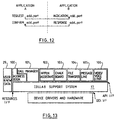
- Program calls to the API generally result in a request, indication, response, confirm sequence.
- An application A requiring a service, requests that service, supplying the appropriate parameters.
- the request usually requires another application B being made aware of that request; the mechanism for this is an unsolicited event which appears as an indication at the application B.
- the action taken by B to the indication event is given to the support system as a response, with appropriate data.
- the system passes the information back to application A as a confirm event. This is illustrated in Figure 12 using the example of the sequence involved in adding a port to a channel (for simplicity no parameters are shown),
- An API call may be either synchronous or asynchronous, depending upon the particular function; a synchronous call returns control when the request is complete, an asynchronous call returns control immediately.
- these calls contain a reference identifier. This identifier is valid until the request has been satisfied and queries can be issued to obtain status; this same identifier can also be used to cancel a pending request. All calls pass back a return code denoting call status.
- An application requests addressability to nodes by using the node name.
- This name is first passed to the local call manager which has the option to modify it.
- the resultant name is then used by the support system to determine connectivity information, this requires access to the externally held network and user data base, using the resources interface.
- the support system determines physical addressability for that name through queries to the network configuration via the resources interface 29, Fig. 2.
- a node handle is returned to the application to reflect this resolution of the node name.
- Addressability from one application to another application requires the resolution of an application name. If both applications are at the same node, the local call manager can perform this resolution, else both call managers must be involved. This resolution results in the target application being identified to the source application by an application handle. Calls using application names are always passed to the call manager for resolution; calls using application handles go direct to the specified application.
- API requests are provided to assist with event and call control.
- a "begin_monitor” request allows an application to monitor requests and events at a node, the scope of the monitoring being controlled by the choice of monitor class from one of the following:
- the scope of the monitoring is controlled at the event or API class level. Events can be monitored with or without data. Monitoring is terminated with an "end_monitor” command. Applications can also use the "enable_events” and “disable_events” commands to determine which events they are to receive.
- the valid event classes are:
- a default event handler generates responses for all events not explicitly handled via an applications. Events are handled by registered event handlers: four types can exist in aware applications:
- All channel ports can be associated with a user exit to monitor data traffic or process data.
- the user exit is invoked immediately prior to the data being transmitted to the receiving nodes; for a receiving port, the user exit is invoked immediately the data arrives at the receiving port but prior to the data being presented to the receiving application.
- Specification of a user exit routine on ports which have been connected may impact performance because the data must be surfaced to the user exit.
- a full set of queries are provided to avoid applications needing to keep track of status information.
- Application program debugging can be simplified by initially running collaborating applications at a single node; thus avoiding physical networks being required during initial stages of program development.
- a number of pre-programmed utilities are provided in order to immediately provide useful function to end users and reduce the programing effort required to develop new collaborative applications, by providing common functions accessible through a command interface.
- the overall architecture is intended to support a broad range of collaborative applications.
- the interface is set at as high a level as possible, consistent with not imposing any significant restraints on the range of application models that may be implemented.
- the nature of the transport networks involved are totally hidden below the API. This means that an application is completely unaware of the network routing (eg direct or indirect), and the network types involved (eg single or multiple links, switched or fixed connections).
- a consequence of this approach is that the applications must be written expecting that requests, for example for a particular communications quality of service, may fail, since the underlying network may not have the required capability.
- An agent philosophy has been implemented so that third party applications can be sued to act on behalf of other applications. This permits call manager, telephony, and switching applications to be developed.
- the current state of technology requries that analog networks and devices should be supported. It is attempted to treat analog networks like digital networks, in order to ease application migration.
- the channel is the other fundamental concept in the architecture.
- Uni-directional channels are used as the basic communications building block to efficiently support both broadcast and two-way communications.
- the channels are established by the sending application, and accepted by the receiving application, because only the sending application can be aware of the properties of the data which dictate how it should be transmitted. Both applications can independently control the format to be supplied or received to or from their respective ports.
- Multiple logical channels, for each kind of data flow, allow the support system to allocate the traffic appropriately to the underlying transport network; moreover it lets other applications have data presented to them in separated, homogeneous flows, each individually described. Additionally this split of the inter-application traffic into individual data types, allow the support system to offer data conversion facilities.
- Connections and welding of channels allows the transport of data to drop below the API so that the application is no longer involved in moving the data.
- the support system has the option, in some cases, of effecting the connection, either at a very low level at that node, or re-routing the flow away from that node.
- the support system architecture is designed to permit inter-working between different computer platforms, operate over varied communications networks, and support relevant communication and data standards.
- the separation of data traffic into logical uni-directional flows of homogeneous data simplifies the mapping on to a mixed network and allows the use of multiple physical links, of different capabilities, between the nodes.
- Data multiplexing is handled below the application and can be implemented in different ways depending upon the underlying transport mechanism, e.g. by a combination of: allocating each logical flow to an individual physical link; multiplexing all the data in the support layer; or by leaving aspects of the multiplexing to a device driver.
- voice, video and data traffic for instance, can be sent over multiple channels, over iso-LAN or iso-Ethernet, or over ISDN using the CCITT H320 recommendations.
- the quality of service requirements impose conditions on the required transport facilities; thus voice and video typically require dedicated physical links or shared links with isochronous capability, implemented through schemes involving priority and bandwidth management.
- the system also provides a separate data class for the interactive objects commonly used in collaborative applications, such as remote pointers, cursors and gestures.
- the following parameters are associated with a channel and are established on the creat_channel and add_channel requests.
- the following parameters are associated with a port; all except port-type are defined explicitly; sending ports specify these parameters on the create_channel request, receiving ports specify them on the PORT_REQUEST response.
- the following quality of service parameters are associated with a physical link and are specified in the network data base accessed via the link locator, or obtained as defaults from the LAKESQOS.INI file.
- the application manager 223 acts as an interface to the rest of the support system, providing an entry point for all the API calls which are then distributed to the appropriate component after a certain amount of parameter verification. It is also used to scan incoming calls/outgoing events if monitoring is required (see below).
- the application manager is responsible for calling back the application at the event handler specified when a channel is created.
- the events will be those raised at the sending port if the local application created the channel, or then receiving port if the remote application created the channel.
- the application manager passes the address of an event queue handler which will handle all the events for a particular application and place them in a queue. Then, some mechanism such as a dispatch thread continuously reading the event queue sends the event to the application's event handler.
- the channel manager 227 has five sub-components: a channel supervisor, responsible for starting and shutting down all the other components; a control channel sub-component, which handles control channel communications between support systems at different nodes; a data channel sub-component, which handles all other non-control channel data communications; a node manager, which creates, destroys, and maintains node handles and sets of node handles; and a port manager, which creates, destroys, and manipulates ports and does port query functions.
- a channel supervisor responsible for starting and shutting down all the other components
- a control channel sub-component which handles control channel communications between support systems at different nodes
- a data channel sub-component which handles all other non-control channel data communications
- a node manager which creates, destroys, and maintains node handles and sets of node handles
- a port manager which creates, destroys, and manipulates ports and does port query functions.
- the resource manager 225 is the first component in the support system to get control. It is responsible for initialising all the other components, as well as interfacing to any address book or route selection facilities.
- the token manager 224 as its name suggests, is responsible for the logging and management of tokens, both global and application tokens (global tokens are owned by the respective call manager components; by contrast application tokens are owned by a node in a sharing set).
- the device manager 224 is responsible for interactions between the support system and devices, and in particular performs the following functions: resolving devices names to fully qualified path etc, loading appropriate dynamic link library (DLL), generating a record containing the port number, port handler and event word, calling the initialisation entry point, and resolving all entry handles in the DLL to physical address for the application call manager.
- the signal manager 226 is responsible for signalling to applications (with or without reply) and to ports.
- the set_call_manager function requests that the issuer be established as the new call manager at the issuing node and identifies the event handler to be invoked for call manager events.
- the set_call_manager() function identified to the subsystem the event handler that is to receive any events of a non-application specific nature, i.e. any incoming events from the network that do not identify a specific application instance. (Note. The events may specify a destination application name, in which case, it is the function of the call manager to resolve the name to a specific instance).
- Only one set_call_manager() event handler can be active at any one time on any given node. More than one set_call_manager() may be issued by applications running on a given node, but the last one issued is the one that is in effect (i.e. that application instance is the call manager for that node).
- a call manager already exists then it will receive a SET_CALL-MANAGER event.
- This existing call manager has the option of allowing the transfer of the call manager function to the new application or rejecting the request. In this case the existing call manager stays in control and the issuer receive the RC_CM_REQUEST_REJECTED return code. This allows some control over which applications are authorised to become call managers.
- the LAKES.INI file can have a section in it, specifying the names of the applications that are authorised to become call managers. So that when a SET_CALL_MANAGER event is raised at the current call manger, it can check in the file via the get_profile_string function call to see if the application is authorised.
- the register_app function registers the name of the issuing application instance and the event handler to handle incoming events.
- the application_name,event_handler and the event_word must be supplied.
- the node_handle and application_handle are returned by the system. They define the unique handles within the node and have no scope or meaning outside of the local node.
- an APP_REGISTER event is raised in the call manager even handler if one exists. If no call manager exists then no event is raised and the issuer of the register_app function call will receive the return code RC_NO_CALL_MANAGER. The issuer should then either become the call manager by issuing the set_call_manager() function call or terminate by issuing the deregister_app() function call.
- the launch function causes the specified target application to be invoked.
- This function is used to ask the system to start another application instance. IF the new application is started successfully then its instance handle is inserted in the target_application and returned to the calling application.
- launch may be issued by any aware application, it is not restricted to the currently active call manager.
- the share function requests that the specified target application be shared with the specified source application.
- the share function request that the source application and target application are to be (or added into) an "application set”.
- the call manager at the relevant node will be invoked, it is then the responsibility of the call manager at the target node to decide how to handle the share request.
- the share request is passed directly to the desired application and does not go via the call manager.
- the user_info parameter would should normally be used to tell the target node how or why the application is to be shard.
- the appropriate return code (RC_SHARE_CONFIRMED or RC_SHARE_REJECTED) will be returned. If the local system receives a subsequent SHARE_CONFIRMED event from the target application then this event is not raised to the issuer of the share function call but is handled by the system generating an appropriate UNSHARE event. IF the local system received a subsequent SHARE_REJECTED event from the target application then this event is ignored.
- a share request specifying an application name rather than a handle is directed to the call manager. This allows the call manager to decide how treat the share, e.g. it could:-
- the call manager If the call manager issued a launch for an application as a result of a SHARE_REQUEST event, it must then re-issue the share request on behalf of the original requester to the launched application.
- the unshare function terminates the sharing between the source application and the applications in its sharing set.
- This function is used to remove an application instance from a set of sharing applications, it does not terminate the application. All other applications in the set will receive an event to indicate that the instance is no longer part of the sharing set.
- the user_info parameter should be used to tell the other instances in the application set why the unshare is being done.
- the event handler set-up by the register_app is still active and will receive events directed via the system or the call manager.
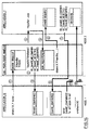
- Typical flows for the control of sharing are illustrated in Figure 14.
- the SHARE_REQUEST event is raised initially in the call manager at the target node.
- the SHARE_REQUEST event is raised directly in the target application.
- the Call Manager plays a key role in determining the behaviour or personality of the subsystem at a workstation.
- the Call Manager utility 101 (Fig. 13) supplied with the subsystem will now be described in detail.
- the supplied call manager utility allows a clear separation of call management and application programming. Use of the shipped call manager therefore removes the need for aware applications to be involved in call set-up or tear-down. It provides dialogues for an end user to select names from the address book and logically establish a multi-point call. Parties can be added and can leave dynamically and several calls may be in progress simultaneously. Options provided include auto-answer and call barring.
- the call manager In order to separate the look and feel of the call manager from the function, the call manager is actually implemented as two separate programs - the engine and the user interface.
- the engine provides call management function, whilst the user interface determines the look and feel.
- the call manager engine has a command interface to allow it to be controlled by other applications (in fact this is how the user interface portion control the engine).
- the engine maintains an application table, for each local application instance currently running, a call table, for each call, a command table for each application currently in the command sharing set (and therefore eligible to send commands to the engine), and a link table, listing each passive link currently in effect.
- the Call Manager lets the user initiate the following actions:
- the user can also set various options, for example to indicate if incoming calls are to be automatically accepted or rejected and how requests for passive working are to be handled.
- the Call Manager user interface consists of a main window, complete with action bar and client area, the latter containing an information area, which displays messages and other status information, as well as context-sensitive prompts for the menu pulldowns.
- the actionbar provides the following options:
- Unshared view of aware applications currently running which are not shared in a call
- Call view a list of the nodes in a call, and for each node, a list of the shared applications which are running there
- Log view which is a separate window, not a child window of the control window, which contains a record of time-stamped events.
- the Call Manager includes event handlers to handle call manager events, such as local application initialisation and named share requests from other nodes.
- a call consists of one or more named sharing sets, sets of application instances which know about each other. Each set consists of a single application that is running at each node within the call. The call manager itself is in one such sharing set for each call. Only the Call Manager (and hopefully the user!) is aware of how the various sharing sets at a given node are grouped into calls.
- the various call manager functions are in fact operations on sharing sets.
- the call manager creates a call name, typically by appending a numeric suffix to the node name, incrementing the number after each call. It then attempts to share, using this name, with the call manager at the remote node. If the share is accepted, the call has been established.
- the call manager merely tries to share with the call manager at the new node, using the call name as the sharing set name.
- the call manager merely tries to share with the call manager at one of the nodes in the call, passing the the name of the call to be joined.
- the Call manager unshares from the appropriate set.
- the call manager issues shares on behalf of the application to each node in the call in turn, using the call name as the sharing set name. Note that once there are applications in the call then each time a new node is added a share will be issued to it for each application.
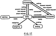
- the call manager There are six main states for the call manager, as shown in Figure 17. These are starting, ready, connected, processing, ending, and resioning. Starting occurs from the point at which the engine is launched until it has completed its initialisation. The engine then enters the ready state, waiting for commands from the user interface of some other application which has shared with the engine. Some of the events passed to the engine's event handler from the support system result in signals being sent to the user interface component so that this in turn can inform the user and if necessary obtain a response which can be fed back via a command to the engine. The engine enters the connected state as soon as a call is in progress. it returns to the ready state as soon as no calls are in progress.
- the engine enters the processing state whenever it is waiting for the user interface to respond or for a support system event to occur. While in this state certain commands, such as call, are rejected with the "engine is busy" indication. Certain support system events, such as SHARE_REQUEST are also rejected.
- the engine enters the ending state as soon as the NODE_SHUT_DOWN_REQUEST event has been received and accepted. Note that the engine must be in the ready state for a shutdown to proceed, if any calls are in progress, these must be terminated first.
- the engine enters the resigning state as soon as it has accepted a CALL_MANAGER_REQUEST. The state is similar to ending in that the engine will terminate, but the rest of the support system will not. The engine will only resign if it is in the ready state, if any calls are in progress these must be terminated first.
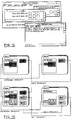
- FIG. 16 shows 4 nodes, A, B, C and D.
- Node C is involved in two calls:
- the Call Manager makes a note of the name of the application which is starting, adding it to the list of applications in the sharing set for the appropriate call, or the unshared list, depending on which is active. If a call is active and the application was started by the user, the Call Manager will issue a named share call to each remote node in the call so that the application gets shared across the call. If the application was launched by the Call manager as a result of an incoming share request, the Call Manager completes the share by issuing a local share on behalf of the remote node/application.
- the Call Manager always returns RC_OK for APP_REGISTERED events.
- the Call Manager checks the state of the Passive Working option. If it is permit, the request is accepted, while if it is deny the request is refused. If it is ask, the Call Manager puts up a dialogue box asking the user if the request is to be accepted (the panel displays as much information about the request as possible) and then accepts or rejects the request depending on the users response (by returning RC_OK or RC_FAIL).
- the two events that the Call Manager is interested in are the results of an unshare call (raised locally) and an unshare event (raised remotely).
- the Call Manager reacts to them by removing the application from the appropriate list.
- the Call Manager responds by dropping them from the appropriate call list. In the case where there were only two parties in the call (i.e. the call has effectively ended), the Call Manager unshares and moves any applications still listed as within the call to the unshared list and then removes the call.
- the Call manager returns RC_OK for all events.
- This event is generated when the channels using the passive link are destroyed.
- the Call Manager merely updates the main window to indicate that the passive link is no longer present and returns RC_OK.
- the Call Manager responds to this event by returning RC_OK, which allows the transfer of the Call Manager role to the new application.
- the Call Manager looks at the name to be resolved. If this is the call manager name, then this is really a request from a remote call manager to start a new call.
- the user info will contain the ID of the call (i.e. the ID assigned by the remote node). This is needed to resolve ambiguity in cases where the two nodes are involved in more than one call with each other.
- the Call Manager responds checking the state of the Answer option. If it is manual, the Call Manager puts up a dialogue box asking the user if the request is to be accepted (the panel displays as much information about the request as possible). If it is auto-answer, the request is accepted. If the request is not from a call manager, it must come from a node which is already a party to an existing call. Because of this, such incoming share requests are always accepted. Note that the incoming share request contains a call ID. This is because a given pair of nodes may have more than one call in common and allows the resulting ambiguity to be resolved. To accept the share request, the Call Manager attempts to launch the corresponding application.
- the Call Manager makes a note of the handle of the launched program, so that when the corresponding Register_app event occurs it doesn't try to share it again (see the APP_REGISTERED event above). If the launch fails, then RC_SHARE_REJECTED is returned. One the other hand if the launch is successful, the Call Manager returns RC_SHARE_NO_CONFIRM. When the launched application later issues register_app, the Call Manager will issue a share call and the application should then return RC_SHARE_CONFIRMED.
- an application launched by the Call Manager will, once it has registered, be the target of a share issued by the Call Manager.
- the Call Manager responds to this event by returning RC_OK, which allows the shutdown to continue. This will in turn cause all applications (including the Call Manager) to receive a SHUT_DOWN event, when the system is actually shutting down. Like the other supplied applications, the Call Manager reacts to this event by de-registering.
- This event is generated when an application terminates.
- the Call Manager responds to this event by removing the name of the de-registering application from the appropriate call list, updating the main window appropriately and returning RC_OK.
- One of the main aims of the Call Manager design is to simplify the structure of an aware application. Since the Call Manager looks after making a call, issuing share and unshare calls and so on, a typical application need only:
Landscapes
- Engineering & Computer Science (AREA)
- Software Systems (AREA)
- Theoretical Computer Science (AREA)
- Physics & Mathematics (AREA)
- General Engineering & Computer Science (AREA)
- General Physics & Mathematics (AREA)
- Multimedia (AREA)
- Computer And Data Communications (AREA)
- Information Transfer Between Computers (AREA)
- Data Exchanges In Wide-Area Networks (AREA)
Abstract
Claims (8)
- Poste de travail programmable pour travailler en collaboration dans un réseau de postes de travail formant les noeuds du réseau, le réseau étant connecté par des liaisons physiques pour la transmission de données entre les noeuds ;le poste de travail comprenant un système d'exploitation ;une couche de programmes de contrôle de réseau, s'exécutant sur le système d'exploitation, pour contrôler l'acheminement physique des données entre les noeuds; etun sous-système d'application en collaboration pour interfacer avec les programmes d'application s'exécutant sur le poste de travail et qui, en réponse à l'appel d'une interface de programmation d'application prédéterminée émanant d'un programme de gestion des appels, établit le programme de gestion des appels en tant que nouveau gestionnaire des appels sur le noeud, chargé de gérer les événements entrants qui ne sont pas spécifiques à un des programmes d'application sur le noeud.
- Poste de travail selon la revendication 1 dans lequel, si un gestionnaire d'appel existe déjà sur le noeud, l'appel d'une interface de programmation d'application prédéterminée est dirigé vers le gestionnaire d'appels existant qui a l'option de transférer la gestion des événements entrants vers le nouveau gestionnaire des appels.
- Poste de travail selon la revendication 1 ou la revendication 2, dans lequel les événements entrants qui sont spécifiques à une instance d'application sont directement transmis à cette instance.
- Poste de travail selon l'une quelconque des revendications précédentes, dans lequel un gestionnaire d'appels répond à des événements spécifiques à aucune application, transmis par le sous-système d'application en collaboration et désignant un programme d'application, en dirigeant les événements vers une instance existante de l'application désignée, en lançant une nouvelle instance de l'application désignée ou en gérant lui-même les événements. désignée, en lançant une nouvelle instance de l'application désignée ou en gérant lui-même les événements.
- Méthode de travail en collaboration dans un réseau de postes de travail programmables formant les noeuds d'un réseau connectés par des liaisons physiques pour la transmission de données entre les noeuds, la méthode comprenant, en réponse à un appel d'interface de programmation d'application prédéterminée provenant d'un programme de gestion des appels s'exécutant sur le poste de travail, l'établissement du programme de gestion des appels en tant que nouveau gestionnaire d'appels sur le noeud, pour gérer les événements entrants qui ne sont spécifiques à aucune instance de programme d'application sur le noeud.
- Méthode selon la revendication 5 dans laquelle, s'il existe déjà un gestionnaire des appels sur le noeud, l'appel d'une interface de programmation d'application prédéterminée est dirigé vers le gestionnaire d'appels existant qui a l'option de transférer la gestion des événements entrants vers le nouveau gestionnaire des appels.
- Méthode selon la revendication 5 ou la revendication 6, dans laquelle les événements entrants qui sont spécifiques à une instance d'application sont directement transmis à cette instance.
- Méthode selon l'une quelconque des revendications 5 à 7, dans laquelle un gestionnaire d'appels répond à des événements non spécifiques à une application et nommant un programme d'application, en dirigeant les événements vers une instance existante de l'application nommée, en lançant une nouvelle instance de l'application nommée ou en gérant lui-même les événements.
Applications Claiming Priority (3)
| Application Number | Priority Date | Filing Date | Title |
|---|---|---|---|
| GB9223520 | 1992-11-10 | ||
| GB9223520A GB2272311A (en) | 1992-11-10 | 1992-11-10 | Call management in a collaborative working network. |
| PCT/GB1993/002314 WO1994011813A1 (fr) | 1992-11-10 | 1993-11-10 | Gestion d'appel dans un reseau fonctionnant en collaboration |
Publications (2)
| Publication Number | Publication Date |
|---|---|
| EP0620935A1 EP0620935A1 (fr) | 1994-10-26 |
| EP0620935B1 true EP0620935B1 (fr) | 2000-09-13 |
Family
ID=10724820
Family Applications (1)
| Application Number | Title | Priority Date | Filing Date |
|---|---|---|---|
| EP93924737A Expired - Lifetime EP0620935B1 (fr) | 1992-11-10 | 1993-11-10 | Gestion d'appel dans un reseau fonctionnant en collaboration |
Country Status (6)
| Country | Link |
|---|---|
| US (1) | US5539886A (fr) |
| EP (1) | EP0620935B1 (fr) |
| JP (1) | JP2544904B2 (fr) |
| DE (1) | DE69329418T2 (fr) |
| GB (1) | GB2272311A (fr) |
| WO (1) | WO1994011813A1 (fr) |
Families Citing this family (88)
| Publication number | Priority date | Publication date | Assignee | Title |
|---|---|---|---|---|
| DE4417588A1 (de) * | 1993-08-30 | 1995-03-02 | Hewlett Packard Co | Verfahren und Vorrichtung zum Erfassen und Weiterleiten von Fensterereignissen zu einer Mehrzahl von bestehenden Anwendungen zur gleichzeitigen Ausführung |
| US5732200A (en) * | 1994-04-19 | 1998-03-24 | International Business Machines Corporation | Integration of groupware with quality function deployment methodology via facilitated work sessions |
| US20100208634A1 (en) | 1994-10-11 | 2010-08-19 | Arbinet Corporation | System and Method For Managing Multimedia Communications Across Convergent Networks |
| US5689645A (en) * | 1994-12-01 | 1997-11-18 | Hewlett-Packard Co. | Persistence specification system and method for producing persistent and transient submaps in a management station for a data communication network |
| EP0744689B1 (fr) * | 1995-05-26 | 2002-10-09 | Intel Corporation | Gestionnaire de type de communication extensible pour système d'ordinateur |
| RU2144283C1 (ru) * | 1995-06-02 | 2000-01-10 | Интел Корпорейшн | Способ и устройство для управления вводом участников в систему конференц-связи |
| US5680323A (en) * | 1995-06-23 | 1997-10-21 | Canon Information Systems, Inc. | Multimedia player |
| US5710882A (en) * | 1995-06-29 | 1998-01-20 | Telefonaktiebolaget Lm Ericsson | Method and call set up server for setting up a call using a call handling portion and a connection handling portion to handle the call and the connection, respectively |
| US6016520A (en) * | 1995-07-14 | 2000-01-18 | Microsoft Corporation | Method of viewing at a client viewing station a multiple media title stored at a server and containing a plurality of topics utilizing anticipatory caching |
| JPH0934843A (ja) * | 1995-07-18 | 1997-02-07 | Canon Inc | 処理システム及び処理装置 |
| US5794006A (en) * | 1995-08-18 | 1998-08-11 | Microsoft Corporation | System and method for editing content in an on-line network |
| US6286034B1 (en) * | 1995-08-25 | 2001-09-04 | Canon Kabushiki Kaisha | Communication apparatus, a communication system and a communication method |
| US5737530A (en) * | 1995-09-28 | 1998-04-07 | Intel Corporation | Method and apparatus for conditionally terminating a personal computer conference |
| JPH09134319A (ja) * | 1995-10-03 | 1997-05-20 | Sony Electron Inc | パーソナル通信ルーティングシステムのユーザインターフェース及びルール処理 |
| US5867156A (en) * | 1995-11-08 | 1999-02-02 | Intel Corporation | Automatic viewport display synchronization during application sharing |
| JP3401587B2 (ja) * | 1995-11-15 | 2003-04-28 | 富士通株式会社 | 仮想近接サービス制御システム |
| GB9603582D0 (en) | 1996-02-20 | 1996-04-17 | Hewlett Packard Co | Method of accessing service resource items that are for use in a telecommunications system |
| US5956027A (en) * | 1995-12-12 | 1999-09-21 | At&T Corp | Method and apparatus for sharing a web page |
| US6154445A (en) * | 1996-04-18 | 2000-11-28 | Bell Atlantic Network Services, Inc. | Telephony communication via varied redundant networks |
| US6069890A (en) | 1996-06-26 | 2000-05-30 | Bell Atlantic Network Services, Inc. | Internet telephone service |
| US5764916A (en) * | 1996-09-27 | 1998-06-09 | Ichat, Inc. | Method and apparatus for real time communication over a computer network |
| US6658466B1 (en) * | 1996-10-16 | 2003-12-02 | Ncr Corporation | Method and apparatus for integrating remote human interactive assistance function into software systems |
| US7263526B1 (en) | 1996-10-30 | 2007-08-28 | Avaya Technology Corp. | Method and apparatus for embedding chat functions in a web page |
| US6785708B1 (en) | 1996-10-30 | 2004-08-31 | Avaya Inc. | Method and apparatus for synchronizing browse and chat functions on a computer network |
| US6078582A (en) | 1996-12-18 | 2000-06-20 | Bell Atlantic Network Services, Inc. | Internet long distance telephone service |
| US20050021477A1 (en) * | 1997-01-29 | 2005-01-27 | Ganapathy Krishnan | Method and system for securely incorporating electronic information into an online purchasing application |
| US6137869A (en) | 1997-09-16 | 2000-10-24 | Bell Atlantic Network Services, Inc. | Network session management |
| US6574216B1 (en) | 1997-03-11 | 2003-06-03 | Verizon Services Corp. | Packet data network voice call quality monitoring |
| US6870827B1 (en) | 1997-03-19 | 2005-03-22 | Verizon Services Corp. | Voice call alternative routing through PSTN and internet networks |
| US6292479B1 (en) | 1997-03-19 | 2001-09-18 | Bell Atlantic Network Services, Inc. | Transport of caller identification information through diverse communication networks |
| US5877757A (en) * | 1997-05-23 | 1999-03-02 | International Business Machines Corporation | Method and system for providing user help information in network applications |
| US6041344A (en) * | 1997-06-23 | 2000-03-21 | Oracle Corporation | Apparatus and method for passing statements to foreign databases by using a virtual package |
| US6049800A (en) * | 1997-06-23 | 2000-04-11 | Oracle Corporation | Mechanism and method for performing callbacks |
| US6236997B1 (en) | 1997-06-23 | 2001-05-22 | Oracle Corporation | Apparatus and method for accessing foreign databases in a heterogeneous database system |
| US5987463A (en) * | 1997-06-23 | 1999-11-16 | Oracle Corporation | Apparatus and method for calling external routines in a database system |
| US6226649B1 (en) | 1997-06-23 | 2001-05-01 | Oracle Corporation | Apparatus and method for transparent access of foreign databases in a heterogeneous database system |
| US6437776B1 (en) * | 1997-06-30 | 2002-08-20 | Barton A. Walz | Video assisted program environment |
| US5958016A (en) * | 1997-07-13 | 1999-09-28 | Bell Atlantic Network Services, Inc. | Internet-web link for access to intelligent network service control |
| CA2246130C (fr) | 1997-09-04 | 2003-01-14 | Mitel Corporation | Service d'assistance web |
| US6105065A (en) * | 1997-10-07 | 2000-08-15 | Nortel Networks Limited | Method of displaying changes in call status between nodes within a connection-oriented network |
| US6239800B1 (en) | 1997-12-15 | 2001-05-29 | International Business Machines Corporation | Method and apparatus for leading a user through a software installation procedure via interaction with displayed graphs |
| US6971109B1 (en) * | 1998-07-24 | 2005-11-29 | Micron Technology, Inc. | Integrated application management system |
| US6807667B1 (en) * | 1998-09-21 | 2004-10-19 | Microsoft Corporation | Method and system of an application program interface for abstracting network traffic control components to application programs |
| US6901594B1 (en) * | 1999-04-23 | 2005-05-31 | Nortel Networks Ltd. | Apparatus and method for establishing communication between applications |
| US6952800B1 (en) * | 1999-09-03 | 2005-10-04 | Cisco Technology, Inc. | Arrangement for controlling and logging voice enabled web applications using extensible markup language documents |
| US6845410B1 (en) * | 1999-09-29 | 2005-01-18 | Silicon Graphics, Inc. | System and method for a hierarchical system management architecture of a highly scalable computing system |
| US6741265B2 (en) * | 1999-11-24 | 2004-05-25 | General Electric Company | Network-based design systems and methods |
| US7003559B1 (en) | 2000-10-23 | 2006-02-21 | Hewlett-Packard Development Company, L.P. | System and method for determining probable network paths between nodes in a network topology |
| US6934766B1 (en) | 2000-11-02 | 2005-08-23 | Cisco Technology, Inc. | Method and apparatus for exchanging event information between computer systems that reduce perceived lag times by subtracting actual lag times from event playback time |
| US8370525B2 (en) * | 2001-03-30 | 2013-02-05 | Intel Corporation | Transmitting new data format under existing infrastructure |
| US20030182388A1 (en) * | 2002-03-20 | 2003-09-25 | Alexander Geoffrey D. | Method and system for portable persistent clipboard function |
| US7178153B1 (en) | 2002-05-10 | 2007-02-13 | Oracle International Corporation | Method and mechanism for implementing an access interface infrastructure |
| US7370336B2 (en) * | 2002-09-16 | 2008-05-06 | Clearcube Technology, Inc. | Distributed computing infrastructure including small peer-to-peer applications |
| US7334018B2 (en) * | 2003-03-11 | 2008-02-19 | Sap Aktiengesellschaft | Unified network resources |
| US7836401B2 (en) * | 2003-03-20 | 2010-11-16 | Siemens Medical Solutions Usa, Inc. | User operable help information system |
| US7613767B2 (en) * | 2003-07-11 | 2009-11-03 | Microsoft Corporation | Resolving a distributed topology to stream data |
| US8503658B2 (en) * | 2003-07-14 | 2013-08-06 | Cisco Technology, Inc. | Call notification with rich caller identification |
| US20050065969A1 (en) * | 2003-08-29 | 2005-03-24 | Shiby Thomas | Expressing sequence matching and alignment using SQL table functions |
| RU2377640C2 (ru) * | 2003-10-23 | 2009-12-27 | Майкрософт Корпорейшн | Архитектура для расширяемой системы совместной работы в реальном времени |
| US8321506B2 (en) * | 2003-10-23 | 2012-11-27 | Microsoft Corporation | Architecture for an extensible real-time collaboration system |
| US20050089023A1 (en) * | 2003-10-23 | 2005-04-28 | Microsoft Corporation | Architecture for an extensible real-time collaboration system |
| US7900140B2 (en) * | 2003-12-08 | 2011-03-01 | Microsoft Corporation | Media processing methods, systems and application program interfaces |
| US7733962B2 (en) * | 2003-12-08 | 2010-06-08 | Microsoft Corporation | Reconstructed frame caching |
| US7712108B2 (en) * | 2003-12-08 | 2010-05-04 | Microsoft Corporation | Media processing methods, systems and application program interfaces |
| US7735096B2 (en) | 2003-12-11 | 2010-06-08 | Microsoft Corporation | Destination application program interfaces |
| US20050185718A1 (en) * | 2004-02-09 | 2005-08-25 | Microsoft Corporation | Pipeline quality control |
| US7934159B1 (en) | 2004-02-19 | 2011-04-26 | Microsoft Corporation | Media timeline |
| US7941739B1 (en) | 2004-02-19 | 2011-05-10 | Microsoft Corporation | Timeline source |
| US7664882B2 (en) * | 2004-02-21 | 2010-02-16 | Microsoft Corporation | System and method for accessing multimedia content |
| US7609653B2 (en) * | 2004-03-08 | 2009-10-27 | Microsoft Corporation | Resolving partial media topologies |
| US7577940B2 (en) * | 2004-03-08 | 2009-08-18 | Microsoft Corporation | Managing topology changes in media applications |
| US7669206B2 (en) | 2004-04-20 | 2010-02-23 | Microsoft Corporation | Dynamic redirection of streaming media between computing devices |
| US7590750B2 (en) * | 2004-09-10 | 2009-09-15 | Microsoft Corporation | Systems and methods for multimedia remoting over terminal server connections |
| US20060161620A1 (en) * | 2004-12-30 | 2006-07-20 | Microsoft Corporation | Extensible activities within collaboration sessions |
| JP4626322B2 (ja) * | 2005-02-03 | 2011-02-09 | 富士ゼロックス株式会社 | プログラム |
| US7584209B2 (en) * | 2005-02-04 | 2009-09-01 | Microsoft Corporation | Flexible file format for updating an address book |
| US7490079B2 (en) * | 2005-04-14 | 2009-02-10 | Microsoft Corporation | Client side indexing of offline address book files |
| JP4738412B2 (ja) * | 2005-07-12 | 2011-08-03 | 富士通株式会社 | 共用管理プログラム、共用管理方法、端末装置、及び共用管理システム |
| US20080259918A1 (en) | 2007-04-19 | 2008-10-23 | Craig Elliott Walker | Method and apparatus for managing telephone calls |
| US8112480B2 (en) * | 2009-01-16 | 2012-02-07 | Microsoft Corporation | Signaling support for sharer switching in application sharing |
| US8238538B2 (en) | 2009-05-28 | 2012-08-07 | Comcast Cable Communications, Llc | Stateful home phone service |
| US8789065B2 (en) | 2012-06-08 | 2014-07-22 | Throughputer, Inc. | System and method for input data load adaptive parallel processing |
| US20130117168A1 (en) | 2011-11-04 | 2013-05-09 | Mark Henrik Sandstrom | Maximizing Throughput of Multi-user Parallel Data Processing Systems |
| US8793698B1 (en) | 2013-02-21 | 2014-07-29 | Throughputer, Inc. | Load balancer for parallel processors |
| US9448847B2 (en) | 2011-07-15 | 2016-09-20 | Throughputer, Inc. | Concurrent program execution optimization |
| CN104765621B (zh) | 2014-01-02 | 2018-05-01 | 国际商业机器公司 | 一种在集群节点中部署程序的方法和系统 |
| JP7031569B2 (ja) * | 2018-11-29 | 2022-03-08 | 日本電信電話株式会社 | 情報作成装置、情報作成方法、および、情報作成プログラム |
| US20240161222A1 (en) * | 2022-11-16 | 2024-05-16 | Nvidia Corporation | Application programming interface to indicate image-to-column transformation |
Family Cites Families (12)
| Publication number | Priority date | Publication date | Assignee | Title |
|---|---|---|---|---|
| US5008853A (en) * | 1987-12-02 | 1991-04-16 | Xerox Corporation | Representation of collaborative multi-user activities relative to shared structured data objects in a networked workstation environment |
| US5280583A (en) * | 1988-05-13 | 1994-01-18 | Hitachi, Ltd. | System and method for performing interlocution at a plurality of terminals connected to communication network |
| US4943996A (en) * | 1989-01-06 | 1990-07-24 | International Business Machines Corporation | Shared access to voice and information |
| US5155842A (en) * | 1989-08-14 | 1992-10-13 | Microsoft Corporation | Logical event notification method and apparatus |
| US5206934A (en) * | 1989-08-15 | 1993-04-27 | Group Technologies, Inc. | Method and apparatus for interactive computer conferencing |
| JP2791146B2 (ja) * | 1989-11-15 | 1998-08-27 | 株式会社日立製作所 | データ処理装置 |
| US5195086A (en) * | 1990-04-12 | 1993-03-16 | At&T Bell Laboratories | Multiple call control method in a multimedia conferencing system |
| JP2865827B2 (ja) * | 1990-08-13 | 1999-03-08 | 株式会社日立製作所 | 会議システムにおけるデータ蓄積方法 |
| JP3161725B2 (ja) * | 1990-11-21 | 2001-04-25 | 株式会社日立製作所 | ワークステーションおよび共同情報処理システム |
| US5293619A (en) * | 1991-05-30 | 1994-03-08 | Sandia Corporation | Method and apparatus for collaborative use of application program |
| US5375068A (en) * | 1992-06-03 | 1994-12-20 | Digital Equipment Corporation | Video teleconferencing for networked workstations |
| US5392400A (en) * | 1992-07-02 | 1995-02-21 | International Business Machines Corporation | Collaborative computing system using pseudo server process to allow input from different server processes individually and sequence number map for maintaining received data sequence |
-
1992
- 1992-11-10 GB GB9223520A patent/GB2272311A/en not_active Withdrawn
-
1993
- 1993-11-10 US US08/256,209 patent/US5539886A/en not_active Expired - Fee Related
- 1993-11-10 JP JP6511849A patent/JP2544904B2/ja not_active Expired - Fee Related
- 1993-11-10 DE DE69329418T patent/DE69329418T2/de not_active Expired - Fee Related
- 1993-11-10 WO PCT/GB1993/002314 patent/WO1994011813A1/fr not_active Ceased
- 1993-11-10 EP EP93924737A patent/EP0620935B1/fr not_active Expired - Lifetime
Also Published As
| Publication number | Publication date |
|---|---|
| JP2544904B2 (ja) | 1996-10-16 |
| JPH07503568A (ja) | 1995-04-13 |
| DE69329418D1 (de) | 2000-10-19 |
| GB9223520D0 (en) | 1992-12-23 |
| EP0620935A1 (fr) | 1994-10-26 |
| WO1994011813A1 (fr) | 1994-05-26 |
| DE69329418T2 (de) | 2001-03-22 |
| GB2272311A (en) | 1994-05-11 |
| US5539886A (en) | 1996-07-23 |
Similar Documents
| Publication | Publication Date | Title |
|---|---|---|
| EP0620935B1 (fr) | Gestion d'appel dans un reseau fonctionnant en collaboration | |
| US5652866A (en) | Collaborative working method and system for a telephone to interface with a collaborative working application | |
| EP0620936B1 (fr) | Travail en collaboration dans un reseau | |
| US5719942A (en) | System and method for establishing a communication channel over a heterogeneous network between a source node and a destination node | |
| EP0497022B1 (fr) | Système de conférence | |
| KR970007047B1 (ko) | 멀티미디어 세션을 스케줄링하는 장치 및 방법 | |
| US7167897B2 (en) | Accessories providing a telephone conference application one or more capabilities independent of the teleconference application | |
| US5887170A (en) | System for classifying and sending selective requests to different participants of a collaborative application thereby allowing concurrent execution of collaborative and non-collaborative applications | |
| JPH07240747A (ja) | 会議システム制御方法、会議装置及び会議システム | |
| US5740384A (en) | Interactive multimedia system using active backplane having programmable interface to reconfigure the media stream produced by each component | |
| US5491798A (en) | Method for network call management | |
| US20130132586A1 (en) | Selective Connection Between Corresponding Communication Components Involved in a Teleconference | |
| US6393494B1 (en) | Method, computer program product, and system for managing connection-oriented media | |
| KR100339374B1 (ko) | 분산처리시스템에서의멀티미디어미들웨어 | |
| Retz | Operating system design considerations for the packet-switching environment | |
| Aldred et al. | An application programming interface for collaborative working | |
| KR100235845B1 (ko) | 실시간 멀티미디어 그룹 통신을 위한 다채널/다세션 관리 방법 | |
| KR100186959B1 (ko) | 상호 참여형 멀티미디어 응용 개발 환경에서의 세션 관리 시스템 및 그 방법 | |
| Aldred et al. | Connection Management in a Lakes environment | |
| KR100307194B1 (ko) | 상호 참여형 멀티미디어 응용 개발 시스템에서의 세션 관리 및 컴포넌트 관리장치와 그 방법 | |
| Aldred et al. | Community networking-a LAKES approach | |
| Aldred et al. | Call Management in a Lakes environment | |
| JPH1188375A (ja) | 管理ソフトウエアを有する伝送システム | |
| Pasquale et al. | Operating System and Window System Research for Distributed Multi-media Applications: A Status Report | |
| Shyu | Development of remote logon and network-wide commands for a local area network |
Legal Events
| Date | Code | Title | Description |
|---|---|---|---|
| PUAI | Public reference made under article 153(3) epc to a published international application that has entered the european phase |
Free format text: ORIGINAL CODE: 0009012 |
|
| 17P | Request for examination filed |
Effective date: 19940727 |
|
| AK | Designated contracting states |
Kind code of ref document: A1 Designated state(s): DE FR GB |
|
| GRAG | Despatch of communication of intention to grant |
Free format text: ORIGINAL CODE: EPIDOS AGRA |
|
| 17Q | First examination report despatched |
Effective date: 19991221 |
|
| GRAG | Despatch of communication of intention to grant |
Free format text: ORIGINAL CODE: EPIDOS AGRA |
|
| GRAH | Despatch of communication of intention to grant a patent |
Free format text: ORIGINAL CODE: EPIDOS IGRA |
|
| GRAH | Despatch of communication of intention to grant a patent |
Free format text: ORIGINAL CODE: EPIDOS IGRA |
|
| GRAA | (expected) grant |
Free format text: ORIGINAL CODE: 0009210 |
|
| AK | Designated contracting states |
Kind code of ref document: B1 Designated state(s): DE FR GB |
|
| PG25 | Lapsed in a contracting state [announced via postgrant information from national office to epo] |
Ref country code: FR Free format text: LAPSE BECAUSE OF FAILURE TO SUBMIT A TRANSLATION OF THE DESCRIPTION OR TO PAY THE FEE WITHIN THE PRESCRIBED TIME-LIMIT Effective date: 20000913 |
|
| REF | Corresponds to: |
Ref document number: 69329418 Country of ref document: DE Date of ref document: 20001019 |
|
| EN | Fr: translation not filed | ||
| PLBE | No opposition filed within time limit |
Free format text: ORIGINAL CODE: 0009261 |
|
| STAA | Information on the status of an ep patent application or granted ep patent |
Free format text: STATUS: NO OPPOSITION FILED WITHIN TIME LIMIT |
|
| 26N | No opposition filed | ||
| PGFP | Annual fee paid to national office [announced via postgrant information from national office to epo] |
Ref country code: DE Payment date: 20011122 Year of fee payment: 9 |
|
| REG | Reference to a national code |
Ref country code: GB Ref legal event code: IF02 |
|
| PGFP | Annual fee paid to national office [announced via postgrant information from national office to epo] |
Ref country code: GB Payment date: 20021106 Year of fee payment: 10 |
|
| PG25 | Lapsed in a contracting state [announced via postgrant information from national office to epo] |
Ref country code: DE Free format text: LAPSE BECAUSE OF NON-PAYMENT OF DUE FEES Effective date: 20030603 |
|
| PG25 | Lapsed in a contracting state [announced via postgrant information from national office to epo] |
Ref country code: GB Free format text: LAPSE BECAUSE OF NON-PAYMENT OF DUE FEES Effective date: 20031110 |
|
| GBPC | Gb: european patent ceased through non-payment of renewal fee |
Effective date: 20031110 |